Table of Contents
Advertisement
Quick Links
Advertisement
Table of Contents
Troubleshooting

Related Manuals for Dell XC430


Summary of Contents for Dell XC430
- Page 1 Dell XC430 Web-Scale Hyperconverged Appliance Owner's Manual...
- Page 2 © 2016 Dell Inc. All rights reserved. This product is protected by U.S. and international copyright and intellectual property laws. Dell and the Dell logo are trademarks of Dell Inc. in the United States and/or other jurisdictions. All other marks and names mentioned herein may be trademarks of their respective companies.
-
Page 3: Table Of Contents
Contents 1 About your system....................8 ........................8 Supported configuration ..................... 8 Front-panel features and indicators ..........................10 LCD panel features ..........................10 Home screen ............................ 11 Setup menu ............................11 View menu ........................... 11 Diagnostic indicators ........................13 Hard drive indicator codes ......................14 iDRAC Direct LED indicator codes .................... - Page 4 ...................... 35 Miscellaneous Settings details ...........................36 About Boot Manager ........................ 36 Entering Boot Manager ......................36 Boot Manager main menu ........................36 Changing the boot order .......................37 Choosing the system boot mode .................... 37 Assigning a system and setup password ................ 38 Using your system password to secure your system ........
- Page 5 ............57 Installing a 3.5-inch hot swappable hard drive carrier blank ................57 Removing a hot swappable hard drive carrier ................58 Installing a hot swappable hard drive carrier ..........59 Removing a hot swappable hard drive from a hard drive carrier ......60 Installing a hot swappable hard drive into a hot swappable hard drive carrier ............................61 Cooling fans...
- Page 6 ........................104 Warning messages ........................104 Diagnostic messages ..........................104 Alert messages 6 Using system diagnostics................105 ....................105 Dell Embedded System Diagnostics ..............105 When to use the Embedded System Diagnostics ........... 105 Running the Embedded System Diagnostics from Boot Manager...
- Page 7 ....105 Running the Embedded System Diagnostics from the Dell Lifecycle Controller ......................106 System diagnostic controls 7 Jumpers and connectors................107 ......................107 System board jumper settings ........................ 108 System board connectors ......................110 Disabling a forgotten password 8 Getting help....................... 111 ..........................
-
Page 8: About Your System
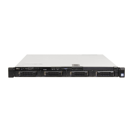
About your system The Dell XC430 system is web-scale converged appliance based on the Dell PowerEdge R430 that supports two Intel Xeon E5-2600 v3 processors, up to 12 DIMMs, and four hard drives or solid-state drives (SSDs). Supported configuration Table 1. Supported configuration... - Page 9 USB regular USB port or provide access to the iDRAC port features. For more information, see the iDRAC User’s Guide available at Dell.com/idracmanuals. USB connector Allows you to connect USB devices to the system. The port is USB 2.0-compliant.
-
Page 10: Lcd Panel Features
The system's LCD panel provides system information and status and error messages to indicate if the system is operating correctly or if the system needs attention. For more information about error messages, see the Dell Event and Error Messages Reference Guide at dell.com/esmmanuals. •... -
Page 11: Setup Menu
SEL. This is useful when trying to match an LCD message with an SEL entry. Select Simple to display LCD error messages in a simplified user-friendly description. For more information about error messages, see the Dell Event and Error Messages Reference Guide at Dell.com/idracmanuals. Set home Select the default information to be displayed on the LCD Home screen. - Page 12 For if any error exists (for more information about the error example, a failed fan or hard messages, see the Dell Event and drive). Error Messages Reference Guide at Dell.com/openmanagemanuals > OpenManage software.
-
Page 13: Hard Drive Indicator Codes
Icon Description Condition Corrective action Reinstall the card. If the issue persists, seeGetting help. NOTE: For more information about supported PCIe cards, seeExpansion card installation guidelines. Hard drive indicator codes Figure 3. Hard drive indicators Hard drive activity indicator Hard drive status indicator Hard drive NOTE: If the hard drive is in Advanced Host Controller Interface (AHCI) mode, the status indicator (on the right side) does not function and remains off. -
Page 14: Idrac Direct Led Indicator Codes
Drive-status indicator pattern Condition Blinks amber four times per second Drive failed Blinks green slowly Drive rebuilding Steady green Drive online Blinks green three seconds, amber three seconds, Rebuild aborted and turns off six seconds iDRAC Direct LED indicator codes This topic describes about the iDRAC Direct LED indicator codes. -
Page 15: Back-Panel Features And Indicators
The following table describes about iDRAC Direct activity when configuring iDRAC Direct using your laptop and cable (Laptop connect). Table 7. iDRAC Direct LED indicator pattern Condition Solid green for two seconds Indicates that the laptop is connected. Flashing green (on for two seconds and off for Indicates that the laptop connected is recognized. - Page 16 Item Indicator, Button, or Icon Description Connector USB connector Allow you to connect USB devices to the system. The port is USB 2.0-compliant. USB connector Allow you to connect USB devices to the system. The port is USB 3.0-compliant. System identification button The identification buttons on the front and back panels can be used to locate a particular system within a rack.
-
Page 17: Nic Indicator Codes
NIC indicator codes Figure 6. NIC indicators link indicator activity indicator Table 9. NIC indicators Conventi Indicator Indicator code Link and activity indicators are off The NIC (network interface card) is not connected to the network. Link indicator is green The NIC is connected to a valid network at its maximum port speed (1 Gbps). - Page 18 NOTE: For AC PSUs, use only PSUs with the Extended Power Performance (EPP) label on the back. Mixing PSUs from previous generations of Dell PowerEdge servers can result in a PSU mismatch condition or failure to turn on. Flashing amber...
-
Page 19: Documentation References
Power is not connected. Documentation references For information about the Dell documents, see the Support Matrix specific for your product. For information about the Nutanix documents that applies to a specific release of Nutanix solution software, see the Support Matrix specific for your product. -
Page 20: Performing Initial System Configuration
Server LCD panel You can configure iDRAC IP by using: iDRAC Web Interface. For more information about setting up and configuring iDRAC, see the Integrated Dell Remote Access Controller User's Guide at Dell.com/idracmanuals. Remote Access Controller ADMin (RACADM). For more information, see the RACADM Command Line Interface Reference Guide and the Integrated Dell Remote Access Controller User's Guide at Dell.com/idracmanuals. -
Page 21: Remote Management
For more information, see the Integrated Dell Remote Access Controller User’s Guide at Dell.com/idracmanuals. You can also remotely monitor and manage the server by using the Dell OpenManage Server Administrator software application and OpenManage Essentials systems management console. For more information, go to Dell.com/openmanagemanuals. -
Page 22: Pre-Operating System Management Applications
• Dell Lifecycle Controller Dell Lifecycle Controller allows you to perform useful tasks such as configuring BIOS and hardware settings, deploying operating system, updating drivers, and saving hardware profiles. For more information about Dell Lifecycle Controller, see the documentation at Dell.com/idracmanuals. -
Page 23: About System Setup
Enables you to enter PXE boot About System Setup Using System Setup, you can configure the BIOS settings, iDRAC settings, and device settings of your system. NOTE: There are a several generic server settings that appear during system setup that do not apply to this system, such as RAID or UEFI. -
Page 24: System Bios Settings Details
UEFI (Unified Extensible Firmware Interface). You can enable or disable various iDRAC parameters by using the iDRAC settings utility. For more information about this utility, see Integrated Dell Remote Access Controller User’s Guide at Dell.com/idracmanuals. Device Settings Enables you to configure device settings. -
Page 25: Memory Settings Details
Operating Mode Advanced ECC Mode, Mirror Mode, Spare Mode, Spare with Advanced ECC Mode, Dell Fault Resilient Mode and Dell NUMA Fault Resilient Mode. This option is set to Optimizer Mode by default. NOTE: The Memory Operating Mode option can have different default and available options based on the memory configuration of your system. -
Page 26: Processor Settings Details
NOTE: This option is only available on certain stock keeping units (SKUs) of the processors. X2Apic Mode Enables or disables the X2Apic mode. Dell Controlled Controls the turbo engagement. Enable this option only when System Profile is set Turbo to Performance. -
Page 27: Sata Settings Details
NOTE: Depending on the number of installed CPUs, there may be up to four processor listings. Number of Cores Controls the number of enabled cores in each processor. This option is set to All per Processor by default. Processor 64-bit Specifies if the processor(s) support 64-bit extensions. - Page 28 Model Specifies the drive model of the selected device. Drive Type Specifies the type of drive attached to the SATA port. Capacity Specifies the total capacity of the hard drive. This field is undefined for removable media devices such as optical drives.
-
Page 29: Boot Settings Details
For AHCI or RAID mode, BIOS support is always enabled. Model Specifies the drive model of the selected device. Drive Type Specifies the type of drive attached to the SATA port. Capacity Specifies the total capacity of the hard drive. This field is undefined for removable media devices such as optical drives. -
Page 30: Network Settings Screen Details
CAUTION: Switching the boot mode may prevent the system from booting if the operating system is not installed in the same boot mode. If the operating system supports UEFI, you can set this option to UEFI. Setting this field to BIOS allows compatibility with non-UEFI operating systems. This option is set to BIOS by default. -
Page 31: Integrated Devices Details
ISCSI Device n (n = Enables or disables the iSCSI device. When disabled, a UEFI boot option is created 1 to 4) for the iSCSI device automatically. Integrated Devices details The Integrated Devices screen details are explained as follows: USB 3.0 Setting Enables or disables the USB 3.0 support. -
Page 32: Serial Communication Details
Memory Mapped Enables or disables the support for PCIe devices that need large amounts of I/O above 4 GB memory. This option is set to Enabled by default. Slot Disablement Enables or disables the available PCIe slots on your system. The slot disablement feature controls the configuration of PCIe cards installed in the specified slot. - Page 33 Custom, the BIOS automatically sets the rest of the options. You can only change the rest of the options if the mode is set to Custom. This option is set to Performance Per Watt Optimized (DAPC) by default. DAPC is Dell Active Power Controller.
-
Page 34: System Security Settings Details
NOTE: This option can be disabled only if the C States option in the Custom mode is set to disabled. NOTE: When C States is set to Enabled in the Custom mode, changing the Monitor/Mwait setting does not impact the system power or performance. System Security Settings details The System Security Settings screen details are explained as follows: Intel AES-NI... -
Page 35: Miscellaneous Settings Details
specification. When set to Controlled, selected UEFI variables are protected in the environment and new UEFI boot entries are forced to be at the end of the current boot order. Secure Boot Enables Secure Boot, where the BIOS authenticates each pre-boot image by using the certificates in the Secure Boot Policy. -
Page 36: About Boot Manager
Launch System Allows you to access the System Setup. Setup Launch Lifecycle Closes the Boot Manager and invokes the Dell Lifecycle Controller program. Controller System Utilities Opens system utilities menu such as system diagnostics and UEFI shell. Changing the boot order You may have to change the boot order if you want to boot from a USB key or an optical drive. -
Page 37: Choosing The System Boot Mode
NOTE: Operating systems must be UEFI-compatible to be installed from the UEFI boot mode. DOS and 32-bit operating systems do not support UEFI and can only be installed from the BIOS boot mode. NOTE: For the latest information on supported operating systems, go to Dell.com/ossupport. Assigning a system and setup password Prerequisites NOTE: The password jumper enables or disables the System Password and Setup Password features. -
Page 38: Using Your System Password To Secure Your System
• Only the following special characters are allowed: white space, (”), (+), (,), (-), (.), (/), (;), ([), (\), (]), (`). A message prompts you to reenter the system password. Reenter the system password and click OK. Select Setup Password, enter your system password and press Enter or Tab. A message prompts you to re-enter the setup password. -
Page 39: Operating With A Setup Password Enabled
The Dell Lifecycle Controller can be started during the boot sequence and can function independently of the operating system. NOTE: Certain platform configurations may not support the full set of features provided by the Dell Lifecycle Controller. For more information about setting up the Dell Lifecycle Controller, configuring hardware and firmware, and deploying the operating system, see the Dell Lifecycle Controller documentation at Dell.com/... -
Page 40: Changing The Thermal Settings
On the System Setup Main Menu page, click iDRAC Settings. The iDRAC Settings screen is displayed. Changing the Thermal settings The iDRAC Settings utility enables you to select and customize the thermal control settings for your system. Enter the iDRAC Settings utility. Under iDRAC Settings →... -
Page 41: Installing And Removing System Components
Damage due to servicing that is not authorized by Dell is not covered by your warranty. Read and follow the safety instructions that are shipped with your product. -
Page 42: Recommended Tools
Steps Install the system cover. If removed, install the optional front bezel. Reconnect the peripherals and connect the system to the electrical outlet. Turn on the system, including any attached peripherals. Recommended tools You will need the following items to perform the procedures in this section: •... -
Page 43: Installing The System Cover
Steps Rotate the latch release lock counter clockwise to the unlocked position. Lift the latch toward the back of the system. The system cover slides back and the tabs on the system cover disengage from the slots on the chassis. NOTE: The position of the latch may vary depending on the configuration of your system. -
Page 44: Inside The System
Damage due to servicing that is not authorized by Dell is not covered by your warranty. Read and follow the safety instructions that came with the product. -
Page 45: Cooling Shroud
Damage due to servicing that is not authorized by Dell is not covered by your warranty. Read and follow the safety instructions that are shipped with your product. -
Page 46: Installing The Cooling Shroud
Damage due to servicing that is not authorized by Dell is not covered by your warranty. Read and follow the safety instructions that are shipped with your product. -
Page 47: System Memory
Next steps Follow the procedure listed in After working inside your system. System memory Your system supports DDR4 registered DIMMs (RDIMMs). NOTE: MT/s indicates DIMM speed in MegaTransfers per second. Memory bus operating frequency can be 2133 MT/s, 1866 MT/s, 1600 MT/s, or 1333 MT/s depending on the following factors: •... - Page 48 Figure 11. System memory Memory channels are organized as follows: Processor 1 channel 0: memory sockets A1 and A5 channel 1: memory sockets A2 and A6 channel 2: memory sockets A3 and A7 channel 3: memory sockets A4 and A8 Processor 2 channel 0: memory sockets B1...
-
Page 49: General Memory Module Installation Guidelines
channel 1: memory sockets B2 channel 2: memory sockets B3 channel 3: memory sockets B4 The following table shows the memory populations and operating frequencies for the supported configurations. Table 11. System memory DIMM DIMMs Operating Maximum DIMM Rank/ Voltage Type Populated/ Frequency (in MT/s) -
Page 50: Sample Memory Configurations
Damage due to servicing that is not authorized by Dell is not covered by your warranty. Read and follow the safety instructions that are shipped with your product. - Page 51 WARNING: The memory modules are hot to touch for some time after the system has been powered down. Allow the memory modules to cool before handling them. Handle the memory modules by the card edges and avoid touching the components or metallic contacts on the memory module.
-
Page 52: Installing A Memory Module
Damage due to servicing that is not authorized by Dell is not covered by your warranty. Read and follow the safety instructions that are shipped with your product. -
Page 53: Satadom
Figure 13. Installing the memory module memory module alignment key memory module socket ejector (2) Next steps Install the cooling shroud. Follow the procedure listed in After working inside your system. Press F2 to enter System Setup, and check the System Memory setting. The System Memory Size indicates the installed memory. -
Page 54: Removing The Satadom
Damage due to servicing that is not authorized by Dell is not covered by your warranty. Read and follow the safety instructions that came with the product. -
Page 55: Installing The Satadom
Damage due to servicing that is not authorized by Dell is not covered by your warranty. Read and follow the safety instructions that came with the product. -
Page 56: Hard Drives
Damage due to servicing that is not authorized by Dell is not covered by your warranty. Read and follow the safety instructions that came with the product. -
Page 57: Installing A 3.5-Inch Hot Swappable Hard Drive Carrier Blank
Damage due to servicing that is not authorized by Dell is not covered by your warranty. Read and follow the safety instructions that came with the product. -
Page 58: Installing A Hot Swappable Hard Drive Carrier
Damage due to servicing that is not authorized by Dell is not covered by your warranty. Read and follow the safety instructions that are shipped with your product. -
Page 59: Removing A Hot Swappable Hard Drive From A Hard Drive Carrier
Damage due to servicing that is not authorized by Dell is not covered by your warranty. Read and follow the safety instructions that are shipped with your product. -
Page 60: Installing A Hot Swappable Hard Drive Into A Hot Swappable Hard Drive Carrier
Damage due to servicing that is not authorized by Dell is not covered by your warranty. Read and follow the safety instructions that are shipped with your product. -
Page 61: Cooling Fans
Damage due to servicing that is not authorized by Dell is not covered by your warranty. Read and follow the safety instructions that are shipped with your product. -
Page 62: Installing A Cooling Fan
Damage due to servicing that is not authorized by Dell is not covered by your warranty. Read and follow the safety instructions that are shipped with your product. -
Page 63: Removing The Expansion Card Riser
Half Height NOTE: The PCIE_G3_X8 and PCIE_G3_X16 are the two different types of risers supported on Dell XC430 systems. You can install an expansion card on the system board only using expansion-card riser. NOTE: The expansion cards are not hot-swappable. -
Page 64: Installing The Expansion Card Riser
Damage due to servicing that is not authorized by Dell is not covered by your warranty. Read and follow the safety instructions that are shipped with your product. -
Page 65: Installing An Expansion Card
Damage due to servicing that is not authorized by Dell is not covered by your warranty. Read and follow the safety instructions that are shipped with your product. -
Page 66: Installing The Optional Idrac Port Card
Damage due to servicing that is not authorized by Dell is not covered by your warranty. Read and follow the safety instructions that are shipped with your product. -
Page 67: Removing An Internal Sd Card
Damage due to servicing that is not authorized by Dell is not covered by your warranty. Read and follow the safety instructions that came with the product. - Page 68 Follow the procedure listed in Before working inside your system.. Steps Locate the internal dual SD module on the system board. If installed, remove the SD cards. Hold the plastic pull tab and pull the dual SD module out of the system board. Figure 19.
-
Page 69: Installing The Internal Dual Sd Module
Damage due to servicing that is not authorized by Dell is not covered by your warranty. Read and follow the safety instructions that are shipped with your product. - Page 70 Damage due to servicing that is not authorized by Dell is not covered by your warranty. Read and follow the safety instructions that are shipped with your product.
-
Page 71: Installing The Integrated Storage Controller Card
Damage due to servicing that is not authorized by Dell is not covered by your warranty. Read and follow the safety instructions that are shipped with your product. - Page 72 Damage due to servicing that is not authorized by Dell is not covered by your warranty. Read and follow the safety instructions that are shipped with your product.
- Page 73 Figure 21. Processor shield opening and closing lever sequence close first socket release lever lock icon processor open first socket release lever unlock icon Position your thumb firmly over the processor open first socket-release lever near the unlock icon and release the lever from the locked position by pushing down and out from under the tab. Similarly, position your thumb firmly over the processor close first socket-release lever near the lock icon and release the lever from the locked position by pushing down and out from under the tab.
- Page 74 Figure 22. Removing and installing a processor close first socket-release lever pin-1 indicator of processor processor slot (4) processor shield open first socket-release lever socket socket keys (4) Hold the tab on the processor shield and rotate the processor shield upward until the open first socket-release lever lifts up.
-
Page 75: Installing A Processor
Damage due to servicing that is not authorized by Dell is not covered by your warranty. Read and follow the safety instructions that came with the product. - Page 76 CAUTION: Do not use force to seat the processor. When the processor is positioned correctly, it engages easily into the socket. b. Align the pin-1 indicator of the processor with the triangle on the socket. c. Place the processor on the socket such that the slots on the processor aligns with the socket keys on the socket.
-
Page 77: Power Supply Units
NOTE: The PSUs must be of the same type and have the same maximum output power. NOTE: For AC PSUs, use only PSUs with the Extended Power Performance (EPP) label on the back. Mixing PSUs from previous generations of Dell PowerEdge servers can result in a PSU mismatch condition or failure to turn on. -
Page 78: Removing A Redundant Power Supply Unit
Damage due to servicing that is not authorized by Dell is not covered by your warranty. Read and follow the safety instructions that are shipped with your product. -
Page 79: Installing A Redundant Power Supply Unit
Damage due to servicing that is not authorized by Dell is not covered by your warranty. Read and follow the safety instructions that are shipped with your product. -
Page 80: Hard-Drive Backplane
While booting, press F2 to enter the System Setup and ensure the battery is operating properly. Enter the correct time and date in the System Setup Time and Date fields. Close the System Setup page. Hard-drive backplane Dell XC430 system configuration supports 3.5-inch (x4) SAS/SATA backplane. -
Page 81: Removing The Hard-Drive Backplane
Damage due to servicing that is not authorized by Dell is not covered by your warranty. Read and follow the safety instructions that came with the product. -
Page 82: Installing The Hard Drive Backplane
Damage due to servicing that is not authorized by Dell is not covered by your warranty. Read and follow the safety instructions that are shipped with your product. -
Page 83: Control Panel Assembly
Damage due to servicing that is not authorized by Dell is not covered by your warranty. Read and follow the safety instructions that came with the product. -
Page 84: Installing The Control Panel
Damage due to servicing that is not authorized by Dell is not covered by your warranty. Read and follow the safety instructions that came with the product. -
Page 85: Removing The Control-Panel Module
Damage due to servicing that is not authorized by Dell is not covered by your warranty. Read and follow the safety instructions that came with the product. -
Page 86: Installing The Control-Panel Module
Damage due to servicing that is not authorized by Dell is not covered by your warranty. Read and follow the safety instructions that came with the product. -
Page 87: Installing The Power Interposer Board
Damage due to servicing that is not authorized by Dell is not covered by your warranty. Read and follow the safety instructions that are shipped with your product. -
Page 88: System Board
Damage due to servicing that is not authorized by Dell is not covered by your warranty. Read and follow the safety instructions that are shipped with your product. -
Page 89: Installing The System Board
Damage due to servicing that is not authorized by Dell is not covered by your warranty. Read and follow the safety instructions that came with the product. - Page 90 Follow the procedure listed in After working inside your system. Import your new or existing iDRAC Enterprise license. For more information, see the Integrated Dell Remote Access Controller User’s Guide available at Dell.com/support/home. Ensure that you: Use the Easy Restore feature to restore the service tag. See Restoring the Service Tag using Easy Restore.
-
Page 91: Trusted Platform Module
Service Tag. Once the Service Tag is entered, it cannot be updated or changed. Click Ok. Import your new or existing iDRAC Enterprise license. For more information, see Integrated Dell Remote Access Controller User's Guide, at Dell.com/ idracmanuals. Restoring the Service Tag using Easy Restore Use the Easy Restore feature if you do not know the Service Tag of your system. -
Page 92: Installing The Trusted Platform Module
Damage due to servicing that is not authorized by Dell is not covered by your warranty. Read and follow the safety instructions that are shipped with your product. -
Page 93: Re-Enabling The Tpm For Txt Users
For more information on initializing the TPM, go to http://technet.microsoft.com/en-us/library/ cc753140.aspx. The TPM Status changes to Enabled, Activated. Re-enabling the TPM for TXT users While booting your system, press F2 to go to System Setup. On the System Setup Main Menu screen, click System BIOS → System Security . From the TPM Security option, select On with Pre-boot Measurements. -
Page 94: Troubleshooting Your System
Damage due to servicing that is not authorized by Dell is not covered by your warranty. Read and follow the safety instructions that are shipped with your product. -
Page 95: Troubleshooting A Serial I/O Device
If the problem is resolved, restart the system, enter the System Setup, and check if the non- functioning USB ports are enabled. Check if USB 3.0 is enabled in System Setup. If enabled, disable it and see if the issue is resolved (older operating systems may not support USB 3.0). -
Page 96: Troubleshooting A Wet System
Damage due to servicing that is not authorized by Dell is not covered by your warranty. Read and follow the safety instructions that are shipped with your product. -
Page 97: Troubleshooting A Damaged System
Damage due to servicing that is not authorized by Dell is not covered by your warranty. Read and follow the safety instructions that are shipped with your product. -
Page 98: Troubleshooting Power Supply Units
Damage due to servicing that is not authorized by Dell is not covered by your warranty. Read and follow the safety instructions that are shipped with your product. -
Page 99: Troubleshooting Cooling Problems
Damage due to servicing that is not authorized by Dell is not covered by your warranty. Read and follow the safety instructions that are shipped with your product. -
Page 100: Troubleshooting System Memory
Damage due to servicing that is not authorized by Dell is not covered by your warranty. Read and follow the safety instructions that are shipped with your product. -
Page 101: Troubleshooting An Sd Card
Damage due to servicing that is not authorized by Dell is not covered by your warranty. Read and follow the safety instructions that are shipped with your product. -
Page 102: Troubleshooting A Storage Controller
Damage due to servicing that is not authorized by Dell is not covered by your warranty. Read and follow the safety instructions that are shipped with your product. -
Page 103: Troubleshooting Expansion Cards
Damage due to servicing that is not authorized by Dell is not covered by your warranty. Read and follow the safety instructions that are shipped with your product. -
Page 104: System Messages
System messages For a list of event and error messages generated by the system firmware and agents that monitor system components, see the Dell Event and Error Messages Reference Guide at Dell.com/idracmanuals. Warning messages A warning message alerts you to a possible problem and prompts you to respond before the system continues a task. -
Page 105: Using System Diagnostics
Using system diagnostics If you experience a problem with your system, run the system diagnostics before contacting Dell for technical assistance. The purpose of running system diagnostics is to test your system hardware without requiring additional equipment or risking data loss. If you are unable to fix the problem yourself, service and support personnel can use the diagnostics results to help you solve the problem. -
Page 106: System Diagnostic Controls
Displays a time-stamped log of the results of all tests run on the system. This is displayed if at least one event description is recorded. For information about embedded system diagnostics, see the ePSA Diagnostics Guide (Notebooks, Desktops and Servers) available at Dell.com/support/home. -
Page 107: Jumpers And Connectors
Jumpers and connectors System board jumper settings For information on resetting the password jumper to disable a password, see Disabling a forgotten password. Table 17. System board jumper settings Jumper Setting Description PWRD_EN The password reset feature is enabled (pins 2–4). BIOS local access is unlocked at the next AC power cycle. -
Page 108: System Board Connectors
System board connectors Figure 33. System board jumpers and connectors Table 18. System board jumpers and connectors Item Connector Description SYS_PWR_CONN (P1) 24-pin power connector FB_USB Front-panel USB connector PIB_CONN Power interposer board connector SATA_CDROM SATA connector CDROM MiniPERC PCIE_G3_X8 (CPU1) Mini PERC card connector SATA_TBU SATA connector tape backup unit... - Page 109 Item Connector Description BATTERY Battery connector TPM_MODULE Trusted platform module connector J_PSWD_NVRAM For more information, see System board jumper settings SLOT3 PCIE_G3_X16(CPU1) PCIe card connector 3 SLOT2 PCIE_G3_X16(CPU1) PCIe card connector 2 NOTE: This system supports two different types of risers: PCIE_G3_X8 and PCIE_G3_X16.
-
Page 110: Disabling A Forgotten Password
Damage due to servicing that is not authorized by Dell is not covered by your warranty. Read and follow the safety instructions that are shipped with your product. -
Page 111: Getting Help
For contact details of Dell Global Technical Support: a. Click Global Technical Support. b. The Technical Support page is displayed with details to call, chat, or e-mail the Dell Global Technical Support team. Dell SupportAssist For an enhanced Support Experience, Dell recommends installing and configuring Dell SupportAssist. -
Page 112: Quick Resource Locator
Use the Quick Resource Locator (QRL) to get immediate access to system information and how-to videos. This can be done by visiting Dell.com/QRL or by using your smartphone or tablet and a model specific Quick Resource (QR) code located on your Dell system. To try out the QR code, scan the following image.
Need help?
Do you have a question about the XC430 and is the answer not in the manual?
Questions and answers