Advertisement
Quick Links
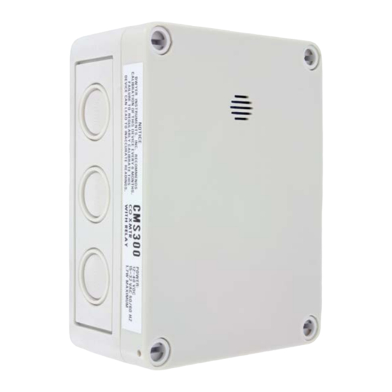
Model CMS300 Carbon Monoxide Transmitter and Switch
Specifications - Installation and Operating Instructions
The Model CMS300 Carbon Monoxide Transmitter and Switch provides a field
selectable current or voltage output that is proportional to the carbon monoxide
concentration in underground parking garages, vehicle maintenance facilities, or
mechanical rooms. An integral relay can be used for alarm conditions and is configured
with preset jumper selectable ranges of 25, 60, or 150 PPM. Field calibration can
be done by using Dwyer Instruments Model GCK-200CO-2000CO2 calibration gas,
Model A-507 calibration adapter, and the on-board zero and span potentiometers.
Disconnect power supply before installation to prevent electrical
WARNING
shock and equipment damage. Make sure all connections are in
accordance with the job wiring diagram and national and local electrical codes. Use
copper conductors only.
Use electrostatic discharge precautions (e.g., use wrist straps)
CAUTION
during installation and wiring to prevent equipment damage.
Avoid locations where mechanical shock or vibration, excessive
CAUTION
moisture or corrosive fumes are present.
CAUTION
Do not exceed ratings of this device; permanent damage not
covered by warranty may result. The 4-20 mA wiring configurations
are not designed for AC voltage operation.
INSTALLATION
These are general guidelines. Local laws or ordinances will
NOTICE
take precedence.
• The transmitter should be mounted at normal breathing height, approximately 5 to
6 ft above the floor.
• The unit may be mounted in the horizontal or vertical position. It should be
mounted in an area that is shielded from direct contact with the elements or direct
sunlight.
• Mount in an area that will prevent the sensor from having any direct contact with
water.
• The unit should be placed in an area that will give an average of the air quality. Do
not place the unit so it will receive direct engine exhaust. Prolonged exposure to
direct engine exhaust may damage the sensor.
MOUNTING
1. Remove the cover plugs from the face of the unit and the top cover.
2. Remove the desired conduit fitting knock out and install conduit fitting (not
provided).
3. Position the transmitter where it is to be mounted and mark the mounting holes in
each corner of the housing.
4. Drill or punch out marked locations.
5. Place the transmitter box over mounting holes on wall and align. Install wall mount
screws (not provided) in mounting holes.
6. Proceed with all wiring according to Figures 1 through 4.
7. Replace cover and cover plugs on the face of the unit.
DWYER INSTRUMENTS, INC.
P.O. BOX 373 • MICHIGAN CITY, INDIANA 46360, U.S.A.
3-45/64 [94.06]
3-1/8 [79.38]
4-17/32
[115.09]
5-7/64
[129.78]
SPECIFICATIONS
Sensor: Electrochemical, 5 years typical lifespan.
Range: 0-300 PPM.
Output Drift: <5% per year in air.
Temperature Effect: ±2% over range.
Coverage Area: 7,500 ft
(700 m
) or 50 ft (15 m) radius.
2
2
Accuracy: ±5 PPM or 5% of reading for 0-300 PPM (whichever is greater).
Resolution: 1 PPM.
Temperature Range: -4 to 122°F (-20 to 50°C).
Storage Temperature: For best sensor life, 32°F to 68°F (0 to 20°C).
Humidity Range: 15-90% RH constant; 0-99% RH intermittent.
Response Time: <45 s to 90% of final value.
Calibration: 15 turn span and zero adjustment potentiometers.
Housing: UV resistant glass filled polycarbonate.
Analog Output: Jumper selectable 4-20 mA (loop powered) or 2-10 V (max. load
2 kΩ).
Enclosure Rating: IP64.
Switch Type: Single-pole double-throw (SPDT).
Relay Electrical Rating: 30 VDC, 250 VAC. N/O=5 A. N/C=3 A resistive.
Set Point: Jumper selectable 25, 60, or 150 PPM.
Set Point Differential/Hysteresis: 3% of scale.
Relay Action: Factory set for direct acting.
Weight: 1 lb (0.45 kg).
Compliance: Sensor is UL recognized component for ANSI/UL-2034, UL-2075,
E340403, CE.
Phone: 219-879-8000
Fax: 219-872-9057
Bulletin AQ-CMS300
4X Ø13/64 [5.16]
2-15/64
MOUNTING HOLES
[56.75]
3-1/8 [79.38]
4-17/32
[115.09]
www.dwyer-inst.com
e-mail: info@dwyermail.com
Advertisement

Related Manuals for Dwyer Instruments CMS300


Summary of Contents for Dwyer Instruments CMS300
- Page 1 [115.09] [115.09] 5-7/64 [129.78] The Model CMS300 Carbon Monoxide Transmitter and Switch provides a field SPECIFICATIONS selectable current or voltage output that is proportional to the carbon monoxide Sensor: Electrochemical, 5 years typical lifespan. concentration in underground parking garages, vehicle maintenance facilities, or Range: 0-300 PPM.
- Page 2 P1, is in the correct position. For 4-20 mA output, the see Figure 1 below for the layout of the board within the CMS300 unit. two right most pins are shorted. For 2-10 V output the two left most pins are shorted.
- Page 3 4. Attach the tubing from the zero calibration gas to the A-507 calibration adapter. Zero 5. Securely attach the A-507 to the CMS300 as shown in Figure 3. 6. Allow the calibration gas to flow at a rate of 0.5 to 1.0 slpm for at least 3 minutes.
- Page 4 __________________________________________________________________________________________________________________________________________ __________________________________________________________________________________________________________________________________________ __________________________________________________________________________________________________________________________________________ __________________________________________________________________________________________________________________________________________ __________________________________________________________________________________________________________________________________________ __________________________________________________________________________________________________________________________________________ __________________________________________________________________________________________________________________________________________ __________________________________________________________________________________________________________________________________________ ©Copyright 2022 Dwyer Instruments, Inc. Printed in U.S.A. 2/22 FR# 444503-00 Rev. 3 DWYER INSTRUMENTS, INC. Phone: 219-879-8000 www.dwyer-inst.com P.O. BOX 373 • MICHIGAN CITY, INDIANA 46360, U.S.A. Fax: 219-872-9057 e-mail: info@dwyermail.com...
Need help?
Do you have a question about the CMS300 and is the answer not in the manual?
Questions and answers