
Related Manuals for Ethicon Gynecare ThermaChoice II


Summary of Contents for Ethicon Gynecare ThermaChoice II
- Page 1 ™ THERMACHOICE II UBT System Service Manual ThermaChoice UBT System Service Manual P/N 01035 Rev. C...
- Page 2 About This Document Overview The THERMACHOICE™II UBT System is a software-controlled device designed to ablate uterine tissue by thermal energy. The system is comprised of a single-use balloon catheter, a reusable controller, umbilical cable, and power cord. The THERMACHOICE™II UBT catheter is designed for use only with the THERMACHOICE™II UBT controller.
- Page 3 How to Use This Guide The GyneCare THERMACHOICE™II UBT Service Manual is an important resource when performing maintenance and service. Read the entire document to become familiar with its content and structure. Use Section One to get an overall understanding of the THERMACHOICE™II UBT System. Later sections will provide details for troubleshooting the individual FRUs, removal and replacement of failed FRUs, and additional reference information.
-
Page 4: Table Of Contents
Contents Section-Page System Overview Device Description Indications Precautions Functional Description of Circuits Diagnostics and Troubleshooting Diagnostic Error Codes Troubleshooting Decision Trees Field Replaceable Unit Listing Table of Field Replaceable Units Catalog of Field Replaceable Units Repair Procedures Assembly, AUX Board 01204 Assembly, ISO Board 00983... - Page 5 Schematics Functional Block Diagram Wiring Diagram Detailed Schematics Electrical/Electronic Parts List THERMACHOICE™II UBT System Operating Manual ThermaChoice UBT System Service Manual P/N 01035 Rev. C...
-
Page 6: System Overview
Section One System Overview Figure 1-1 Device Description The THERMACHOICE™II UBT System is a software-controlled device designed to ablate uterine tissue by thermal energy. The system is comprised of a single-use balloon catheter, a reusable controller, umbilical cable, and power cord. The THERMACHOICE™II UBT catheter is designed for use only with the THERMACHOICE™II UBT controller. -
Page 7: Indications
c) Balloon catheter version 1.2: This version does not have a fluid circulation mechanism inside the balloon. Indications The THERMACHOICE™II UBT System is a thermal ablation device intended to ablate the endometrial lining of the uterus in pre-menopausal women with menorrhagia (excessive uterine bleeding) due to benign causes for whom childbearing is complete. - Page 8 Product Overview The THERMACHOICE™II Uterine Balloon Therapy (UBT) system is an instrument designed to ablate endometrial tissue in the uterus, where excessive uterine bleeding is diagnosed. A balloon on a semi-rigid plastic catheter containing a resistive heating element is inserted into the uterus and manually filled with sterile D5W to a pre-specified pressure range.
- Page 9 Motor Drive Unit (MDU) Central Processing Unit (CPU) User Interface, Front Panel Display For more information regarding the procedure set up, operation of the device, messages, error conditions, unit calibration, etc. refer to Appendix A of the User Manual. Transformer, Power Supplies and Isolation The system operates on 100 to 240 VAC and 60 Hz power lines.
- Page 10 These are two of the nine inputs to the multiplexing analog-digital converter (ADC). The ADC is a high precision serial ADC that operates from an independent voltage source and a 5.000 VDC precision voltage reference. The positive and negative terminals of each of the two thermocouples are connected to the inputs of the amplifiers through two single pole double throw relays.
- Page 11 The current in the heater is constantly monitored while the heater voltage is greater than 2.8 volts. If the current is less than 0.14 amps or greater than 2.5 amps, the controller will shut down with and generate an Error 65. If the heater voltage varies more than +/- 10% from the desired control voltage, the same error is generated.
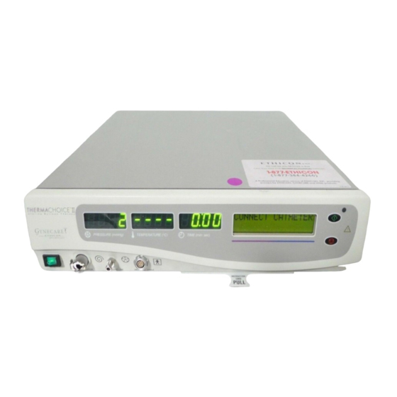
- Page 12 Front Panel Display, User Interface The power switch is located on the front panel. It is an illuminated switch that breaks both line and neutral of the AC line on the primary side of the transformer. The thermocouple temperature of the catheter, the pressure of the balloon, and the time of the procedure are displayed by three LED seven segment type displays.
- Page 13 Specifications POWER SOURCE (Controller) Power Requirements 100 to 240VAC; 50/60 Hz; 110 watts; 3-wire grounded system Regulation Voltage 90 to 264VAC, 47-63 Hz, single phase Mains Fuses 250VAC, 5x20 mm 1.6A standard Heater Fuse 250VAC, 4.0A slo-blo MECHANICAL CHARACTERISTICS Dimensions Height 10.2 cm (4 in.), width 41.2 cm (16.25 in.), depth 37.0 cm (14.56 in.) Weight...
- Page 14 Section Two Diagnostic and Troubleshooting Guide Error Codes The instrument will perform a power-up self test every time the unit is started. If an error is detected, it will appear on the display if possible. Note: The Error Code Format is: xxyy, where xx=error code and yy=system state. Reference the first two numbers on the display for use with the table below.
- Page 15 2. First troubleshooting step should be to perform a visual inspection of the connectors making sure they are seated properly. 3. Check FRUs by swapping out the suspect FRU with a known good FRU. 4. Replace the Micro Assembly to correct problems with the Pressure display, Temperature display, Time display, Start Button Light, or the Hazard Light.
- Page 16 Section Three Field Replaceable Units Power Entry Power Module Supply PN 01353 PN 00808 Assy, ISO, Assy, Micro Display, LCD Assy, AUX Switch, Assy, PN 00983 PN 01200 PN 00877 PN 01204 Power, Motor (behind front (on Micro Mains Drive Unit bezel) Assy, w/ Flex PN 01033...
- Page 17 Assy, Cable, GND, EQPOST- CHASSIS PN 00866 Assy, Cable, Assy, Cable, Assy, Cable, PWR,ENTRY GND-PS- DC 150W PN 00868 CHASSIS PN 00855 PN00864 Assy, Cable, Assy, Cable, Assy, Cable, Assy, Cable, Ribbon, 40 CCS_SWITCH Surge ISO-Micro Cond, 3.5” PN 01293 Arrestor PN 01504 PN 00874...
-
Page 18: Table Of Field Replaceable Units
Table of Field Replaceable Units Common Name Bill of Materials Designation Assy No. AUX Board ASSY,PCBA,AUXILLARY 01204 ISO Board ASSY,PCB,ISO 00983 Micro Board ASSY,PCBA,MICROPROCESSOR 01200 Motor Drive Unit (MDU) ASSY,MOTOR DRIVE UNIT 01014 Power Supply PSUPPLY,UNIV INPUT,+5V,-24V-/-12V 00808 Power Entry Module (PEM) PEM,FILTER,W/FUSEHOLDER 01353 Power Switch, Mains... - Page 19 AUX Board ASSY,PCBA,AUXILLARY PN 01204 ISO Board ASSY,PCBA,ISO PN 00983 Micro Board ASSY,PCBA, MICROPROCESSOR PN 01200 ThermaChoice UBT System Service Manual 3 - 4 P/N 01035 Rev. C...
- Page 20 Motor Drive Unit ASSY,MOTOR DRIVE UNIT PN 01014 Power Supply PSUPPLY,UNIV INPUT,+5V,-24,V- /-12V PN 00808 (ground cable not included) Power Entry Module PEM,FILTER, W/FUSEHOLDER, 3A,.250"TERM PN 01353 ThermaChoice UBT System Service Manual 3 - 5 P/N 01035 Rev. C...
- Page 21 Power Switch SWITCH,SPDT,3AMP,.187"TERM,MDU PN 01033 LCD Display DISPLAY,LCD,16X2,BACKLIT PN 00877 Note: Assy, Cable, FLEX, 1X16,4.5", LCD is attached PN 00881 ThermaChoice UBT System Service Manual 3 - 6 P/N 01035 Rev. C...
- Page 22 Heater Fuse FUSE,5x20MM,SLOWBLOW,4,0A,250 PN 01620 Power Entry Module Fuse FUSE,5x20MM,FASTBLOW,1.6A,250 PN 00861 ThermaChoice UBT System Service Manual 3 - 7 P/N 01035 Rev. C...
- Page 23 Eqpost Ground Cable ASSY,CABLE,GND, EQPOST-CHASSIS PN 00866 Power Entry Cable ASSY,CABLE,POWER,ENTRY PN 00868 ThermaChoice UBT System Service Manual 3 - 8 P/N 01035 Rev. C...
- Page 24 Ribbon Cable ASSY,CABLE,RIBBON,40COND, 3.5" PN 00874 CCS Switch Cable ASSY,CABLE,CCS_SWITCH PN 01293 ThermaChoice UBT System Service Manual 3 - 9 P/N 01035 Rev. C...
- Page 25 ISO-Micro Cable ASSY,CABLE,ISO-MICRO PN 01504 Power Supply Cable ASSY,CABLE,DC,150W PN 00855 Power Supply Ground Cable ASSY,CABLE,GND-PS-CHASSIS PN 00864 ThermaChoice UBT System Service Manual 3 - 10 P/N 01035 Rev. C...
- Page 26 Surge Arrestor ASSY,CABLE,SURGE ARRESTOR PN 01347 ThermaChoice UBT System Service Manual 3 - 11 P/N 01035 Rev. C...
-
Page 27: Repair Procedures
Section Four Repair Procedures Assembly, AUX Board 01204 Warning: Disconnect the AC power from the device before servicing. Failure to observe this precaution could result in death or injury. Required Tools: Oval security screwdriver (TR Fastenings, Montgomery Village, MD, Phone 301-947-1001, Part Description: MonoDrive One), 5/16" nut driver Caution: The interior of the instrument is ESD sensitive. -
Page 28: Assembly, Iso Board 00983
Assembly, ISO Board 00983 Warning: Disconnect the AC power from the device before servicing. Failure to observe this precaution could result in death or injury. Required Tools: Oval security screwdriver (TR Fastenings, Montgomery Village, MD, Phone 301-947-1001, Part Description: MonoDrive One), 3/32" Allen wrench, needle nose pliers, #1 Phillips screwdriver, 9/64”... - Page 29 Note: The following two steps involve spring loaded parts. Use care to cover the circulation connector during disassembly to prevent loss of parts. Illustration showing depressing of latch retention pin for latch disassembly. Use caution: both latch and retention pin are spring loaded. Slide the circulation connector slide lock in so that you can depress the retention pin into the circulation connector and covering the connector with your hand, slowly release the slide lock until the retention pin and spring are released.
-
Page 30: Power Supply 00808
17. Use a #1 Phillips screwdriver to remove the 5 screws, washers, and lockwashers that hold the Micro PCBA to the bezel. The Micro PCBA does not need to be separated from the bezel; it only needs to be free to move to allow the removal and installation of the umbilical cable. - Page 31 Caution: The interior of the instrument is ESD sensitive. Use appropriate ESD precautionary procedures. Removal: 1. Using the Oval security screwdriver, remove the four fasteners securing the upper half of the case and remove the upper half of the case. 2.
- Page 32 3. Install the Power Supply support bracket to the sub-chassis with 2 keps nuts and 2 washers. Torque at 89 –91 in./oz. 4. Install the sub-chassis onto the thread studs of the lower housing. 5. Secure the sub-chassis to the lower housing using 3 keps nuts positioned in the upper right and lower left and right.
-
Page 33: Power Entry Module (Pem) 01353
21. Install the upper half of the case, using the Oval security screwdriver to install the four fasteners. Power Entry Module (PEM) 01353 Warning: Disconnect the AC power from the device before servicing. Failure to observe this precaution could result in death or injury. Required Tools: Oval security screwdriver (TR Fastenings, Montgomery Village, MD, Phone 301-947-1001, Part Description: MonoDrive One), #1 Phillips screwdriver, 3/32"... -
Page 34: Assembly, Motor Drive Unit (Mdu) 01014
Replacement: 1. Remove the fuse drawer from the Power Entry Module using a flat blade screwdriver. 2. Remove and verify that fuses are 250V, 1.6 amp fuses. Replace if necessary. 3. Install the fuse drawer into Power Entry Module. 4. With the fuse drawer down, position and insert Power Entry Module into rear panel. 5. - Page 35 Removal: 1. Using the Oval security screwdriver, remove the four fasteners securing the upper half of the case and remove the upper half of the case. 2. Disconnect the two fast-on connectors from the Power Entry Module. 3. Disconnect the Power Entry Cable from the Power Supply. 4.
-
Page 36: Heater Fuse 01620
Note: Ensure that the isolation washers are in place. 6. Using the #1 Phillips screwdriver, install the grounding wires from the Patient Cable and surge suppressor to the MDU mounting bracket. Torque the fasteners to 79 – 81 in./oz. Note: Due to different lead lengths, observe polarity when connecting the CCS Switch Cable to the CCS Switch. -
Page 37: Power Entry Module Fuse 00861
2. On the AUX Board, at location F1F2, remove and inspect the 250V 4.0 amp fuse. Replacement: Caution: Replace only with 250V, 4.0 amp slo-blo fuses 1. Replace the fuse if necessary. 2. Install the upper half of the case, using the Oval security screwdriver to install the four fasteners. - Page 38 Required Tools: Oval security screwdriver (TR Fastenings, Montgomery Village, MD, Phone 301-947-1001, Part Description: MonoDrive One), 9/64” Allen wrench, 5/64" Allen wrench, #1 Phillips screwdriver, 3/32" Allen wrench, needle nose pliers Caution: The interior of the instrument is ESD sensitive. Use appropriate ESD precautionary procedures.
-
Page 39: Lcd Display 00877
Replacement: 1. Install the Micro Board onto the front bezel with the 5 fasteners, washers and lock washers. Torque the fasteners at 59 – 61 in./oz. Caution: 1. Over tightening fasteners in Step 4 will damage inserts. 2. Attach and secure with fasteners, the ISO Cable to the Micro D-Sub P. 3. -
Page 40: Switch, Power, Mains 01033
Removal: 1. Using the Oval security screwdriver, remove the four fasteners securing the upper half of the case and remove the upper half of the case. 2. Put controller unit on its right side. 3. Follow steps 3 through 17 in the Micro Board removal section to gain access to the LCD Display. - Page 41 4. Follow the procedure described in steps 8 and 9 in the ISO Board removal section for removal of the springs and retention pin of the circulation connector. 5. Set controller unit on its base. 6. Using the 9/64” Allen wrench, remove the 2 socket head cap screws which retain the front bezel to the side extrusion.
-
Page 42: Power Entry Cable 00868
13. Attach the Power Entry Cable faston connectors to the Power Entry Module (blue wire – lower left, brown wire – lower right). 14. Install the ISO board in the ISO box base. 15. Install the ISO cover onto the ISO box base including the 2 4-40 socket head cap screws. -
Page 43: Power Supply Cable 00855
11. Disconnect the fast-on connectors from the Power Entry Module. 12. Disconnect the ribbon cable from the Micro board at JP1. 13. Grasp the front bezel and tilt it forward. Disconnect fast-on connectors from the Power Switch. Replacement Note: Observe the labeling on the connectors of the Power Entry Cable to attach the cable to the Power Switch. -
Page 44: Iso Micro Cable 01504
Required tools: Oval security screwdriver (TR Fastenings, Montgomery Village, MD, Phone 301-947-1001, Part Description: MonoDrive One), wire cutter Caution: The interior of the instrument is ESD sensitive. Use appropriate ESD precautionary procedures. Removal: 1. Using the Oval security screwdriver, remove the four fasteners securing the upper half of the case and remove the upper half of the case 2. -
Page 45: Ccs Switch Cable 01293
6. Remove ISO Board from box base. 7. Using the #1 Phillips screwdriver, remove the 2 Phillips screwdriver head screws from the P2 Cable connector. 8. Using the 3/36" Allen wrench, remove the fasteners securing the connector at the Micro Board location P1 and remove the ISO-Micro Cable. Replacement: 1. -
Page 46: Ribbon Cable, 40 Cond. 00874
2. Disconnect the Cable from the Micro Board JP2 connection. 3. Disconnect the Cable from the center and 90-degree lugs of the MDU limit switch. Replacement: 1. Connect the Cable to the Micro Board JP2 connection. Note: Due to different lead lengths, observe polarity when connecting the CCS Switch Cable to the Power Switch. -
Page 47: Assy, Cable, Surge Arrestor 01347
Ribbon Cable should arch upward. 1. At the AUX Board JP4 connection, connect the Ribbon Cable. 2. At the Micro Board JP1 connection, connect the Ribbon Cable. 3. Install the upper half of the case, using the Oval security screwdriver to install the four fasteners. -
Page 48: Maintenance
Section Five Maintenance Calibration Every time the THERMACHOICE™II UBT System is powered up, the controller checks the calibration of the temperature circuitry. The pressure measurement in the system is accomplished by utilizing two transducers. These transducers are internally calibrated and are temperature compensated which are accurate and stable over the operating range. - Page 49 6. Male luer lock adapter: PN B0850402, Braun Medical, Inc., 824 Twelfth Ave., PO Box 4027, Bethlehem, PA 18018-0027, Telephone: (610) 266-0500. Procedure: 1. With no attachments to the luer lock, apply power to the controller. The pressure display should read 0+1 mmHg. 2.
- Page 50 Appendix A Schematics ThermaChoice UBT System Service Manual A - 1 P/N 01035 Rev. C...
- Page 51 Appendix B Electrical/Electronic Parts List ThermaChoice UBT System Service Manual B - 1 P/N 01035 Rev. C...
- Page 52 Appendix C Operating Manual ThermaChoice UBT System Service Manual P/N 01035 Rev. C...
Need help?
Do you have a question about the Gynecare ThermaChoice II and is the answer not in the manual?
Questions and answers