Oxygen 8 NOVA Series Operation And Maintenance
Hide thumbs
Also See for NOVA Series:
- Installation manual (42 pages) ,
- Application, operation & maintenance (68 pages) ,
- Operation & maintenance manual (80 pages)
Table of Contents
Advertisement
Advertisement
Table of Contents

Related Manuals for Oxygen 8 NOVA Series


Summary of Contents for Oxygen 8 NOVA Series
- Page 1 OPERATION & MAINTENANCE NOVA SERIES...
-
Page 2: Table Of Contents
Table of Contents 1.0 General Information 5.6 Alarm and Log 5.7 Status Display 2.0 Configuration Chart 5.8 Control System Information 5.9 Email Settings 3.0 Specifications 5.10 Status Display 3.1 System Overview 6.0 Maintenance 3.2 General Specifications 3.3 Electrical - ERV/DOAS 6.1 Fans 3.4 Electrical - Fan Coil 6.2 DX Coil... -
Page 3: General Information
Operation and Maintenance Manual Nova Series 1.0 General Information Warnings and Caution This manual includes important instructions for safe installation, operations and maintenance of the Energy Recovery Ventilator (ERV). Before installing the ERV, Warnings and cautions appear at the appropriate please read carefully and follow all of the instructions sections throughout this manual. -
Page 4: Configuration Chart
Operation and Maintenance Manual Nova Series 2.0 Configuration Chart The following is a complete description of the packaged ERV/HRV model numbers and nomenclature. Main Code: NOVA_XXX_XXX_X_X_X_X_XX_X_XX_XX_XX_XX_XXX_XX_XX_X_X_X NOVA_A16_ERV_B_I_R_H_S1_ND_01_02_3A_04_2401_13_08_2_1_A Sales Drawings: NOVA_A16_ERV_B_I_R_H_S1_ND_01_02_3A_04_A 1A (Optional) Upper Outlet Air Connection Straight - 01 3A (Optional) -
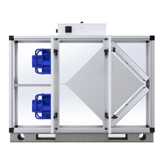
Page 5: Specifications
Operation and Maintenance Manual Nova Series 3.0 Specifications 3.1 System Overview Standard units come complete with energy recovery option, EC fans, 2" filters, fully integrated controls and casing as outlined in the spec below. 3.2 General Specifications Standard Features Warranty... -
Page 6: Electrical - Erv/Doas
Operation and Maintenance Manual Nova Series 3.3 Electrical ― DOAS/ERV Model Nom. V. Motor SA Fan FLA SA Fan FLA Tnsfmr FLA MROP D Rcmd Fuse A16/A18 2.50 2.50 0.29 5.91 8.41 B20/B22 0.78 3.90 3.90 0.29 9.06 12.96 B20/B22 2.00... -
Page 7: Fan And Core Performance
Operation and Maintenance Manual Nova Series 3.4 Fan and Core Performance ERV Performance Model Airflow (cfm) PD (Supply, Return) 1" Insulation / Indoor Units 0.36, 0.72 0.62, 1.26 0.33, 0.55 1300 0.6, 1.05 0.33, 0.55 1300 0.6, 1.05 1550 0.45, 0.79 2700 0.86, 1.64... - Page 8 Operation and Maintenance Manual Nova Series Fan Data Model Nominal Voltage / FLA (A) FLA (A) SP "Wg A16/A18 240/1/60 / 1.8 B20/B22 1300 2401/60 / 2.8 0.78 B20/B22 1300 208/3/60 / 2.8 B20/B22 1300 460/3/60 / 2.8 C20/C22 2200 208/3/60 / 5.0...
-
Page 9: Air Performance
Operation and Maintenance Manual Nova Series Air Performance A16 ― 775 cfm ― 240/1 B20 ― 775 cfm ― 240/1 B20 ― 1300 cfm ― 208/3 B20 ― 1300 cfm ― 460/3 C20 ― 1600 cfm ― 208/3 C20 ― 1600 cfm ― 460/3... - Page 10 Operation and Maintenance Manual Nova Series Air Performance C24 ― 2700 cfm ― 208/3 C24 ― 2700 cfm ― 460/3 C30 ― 3500 cfm ― 208/3 C30 ― 3500 cfm ― 460/3 C40 ― 4400 cfm ― 208/3 C40 ― 4400 cfm ― 460/3...
- Page 11 Operation and Maintenance Manual Nova Series Air Performance C48 ― 5400 cfm ― 208/3 C48 ― 5400 cfm ― 460/3 C58 ― 6600 cfm ― 208/3 C58 ― 6600 cfm ― 460/3 C70 ― 8100 cfm ― 208/3 C70 ― 8800 cfm ― 460/3...
-
Page 12: Dimensions
Operation and Maintenance Manual Nova Series 3.5 Dimensions... - Page 13 Operation and Maintenance Manual Nova Series...
- Page 14 Operation and Maintenance Manual Nova Series...
- Page 15 Operation and Maintenance Manual Nova Series...
- Page 16 Operation and Maintenance Manual Nova Series...
- Page 17 Operation and Maintenance Manual Nova Series...
- Page 18 Operation and Maintenance Manual Nova Series...
-
Page 19: Configuring Controls
Operation and Maintenance Manual Nova Series 4.0 Configuring Controls 4.1 Setting the Fan Operating Points Setting Control Functions Under the “Installer->Operating->Setpoint” tab, you can set the way in which fans and air volumes are to be controlled and regulated. Fans and air volumes can be controlled according to the following operating modes: see next pages. - Page 20 Operation and Maintenance Manual Nova Series Constant Pressure Constant VOC/CO2 • Supply and return fans are controlled in relation • The system must be configured with a CO2 to the pressure in the Supply and return ducts sensor. respectively. •...
-
Page 21: Fan Control: Constant Pressure
Operation and Maintenance Manual Nova Series 4.2 Fan Control: Constant Pressure In order for the pressure range to be set correctly, the pressure transmitter actually installed must first be set correctly. Click the “Transducer” button for Supply and return respectively and set the pressure transmitter’s maximum range (in Pa), which also corresponds to the maximum output signal from the pressure transmitter (10V). -
Page 22: Fan Control: Constant Flow
Operation and Maintenance Manual Nova Series 4.3 Fan Control: Constant Flow Supply Return Low Speed Low Speed • Set the required setpoint for Supply flow at "Low" • Set the required setpoint for return flow at “Low” speed speed High Speed High Speed •... -
Page 23: Fan Control: Return Air Pressure
Operation and Maintenance Manual Nova Series 4.4 Fan Control: Return Air Pressure Transmitter Adjustment In order for the pressure range to be set correctly, the pressure transmitter actually installed must first be set correctly. Click the “Transducer” button for Supply and return respectively and set the pressure transmitter’s maximum range (in Pa), which also corresponds to the maximum output signal from the pressure transmitter (10V). -
Page 24: Fan Control: Supply Air Pressure
Operation and Maintenance Manual Nova Series 4.5 Fan Control: Supply Air Pressure Transmitter Adjustment In order for the pressure range to be set correctly, the pressure transmitter actually installed must first be set correctly. Click the “Transducer” button for Supply and return respectively and set the pressure transmitter’s maximum range (in Pa), which also corresponds to the maximum output signal from the pressure transmitter (10V). -
Page 25: Fan Control: Constant Co2
Operation and Maintenance Manual Nova Series 4.6 Fan Control: Constant CO2 The function is used to maintain a constant/maximum CO2 level in a room or return duct. If the CO2 level is higher than the setpoint, return volume will be increased in a modulated fashion to max. air volume. -
Page 26: Fan Control: Compensation
Operation and Maintenance Manual Nova Series 4.7 Fan Control: Compensation Compensation of ventilation level depending on outside temperature. When outside temperature drops, fan speed can be reduced according to a set curve. The setpoint will be offset to the compensated setpoint when the outdoor temperature is within the set compensation curve. -
Page 27: Alarm Relay Function
Operation and Maintenance Manual Nova Series 4.8 Alarm Relay Function The system can be configured with two digital outputs, which can be configured to follow A-alarms and/or B-alarms. The two digital outputs are configured under “OJ Modules > Configure > Digital I/O”. -
Page 28: Constant Room
Operation and Maintenance Manual Nova Series 4.10 Constant Room 4.12 Cooling The function is only available if active cooling in the form of a cooling element is installed and configured. The function is used to ensure that active cooling can be used if certain set preconditions are met. -
Page 29: Summer Night Cooling (Free Cooling)
Operation and Maintenance Manual Nova Series 4.13 Summer Night Cooling Summer Night Cooling (Free Cooling) Summer night cooling is activated if there was less than 60 minutes heating demand between 12.00 The function is used to cool the room with fresh cold noon and 23.59, during the latest operation period... - Page 30 Operation and Maintenance Manual Nova Series summer night cooling are met, the system will remain Setpoint Supply Air Fan in operation until the stop conditions are met. Fan • Give-in the setpoint for supply air fan during speed is fixed to 50% in this operating mode.
-
Page 31: Humidification
Operation and Maintenance Manual Nova Series 4.14 Humidification Min. Humidity The function is used to humidify the supply air. • Set setpoint for min. humidity alarm The air humidifier, and thus the humidity in the supply • If the system is only configured with a humidity... -
Page 32: Dehumidification
Operation and Maintenance Manual Nova Series 4.15 Dehumidification The function is used to lower the relative humidity in the room by dehumidification. The dehumidification process is intelligently controlled by three moisture sensors (HTH-20X). When dehumidification of the room is demanded,... -
Page 33: Summer/Winter Compensation
Operation and Maintenance Manual Nova Series 4.16 Summer/Winter Compensation 4.17 Summer/Winter Changeover Under the tab: Under the “Installer->Summer/Winter->Changeover” tab, you can choose automatic switching between “Installer->Summer/Winter->Compensation”, it different operating modes depending on outside is possible to set temperature compensation temperature. -
Page 34: Locking The Fan Speed
Operation and Maintenance Manual Nova Series 4.18 Locking the Fan Speed Adjustment Under the tab: “Installer->Adjustment->Setpoint”, the installer can lock fan speed. The function, which is used for VAV installations in particular, allows the installer to maintain constant air quantity during system adjustment. -
Page 35: Communication Protocols
Operation and Maintenance Manual Nova Series 4.19 Communication Protocols External Communication Modbus Setting communication parameters for TCI/IP, LAN, Settings for external Modbus RTU Web browser and BMS Set Internet Connection Static/Dynamic • DHCP = IP address assigned from DHCP server... - Page 36 Operation and Maintenance Manual Nova Series BACnet Language Settings for external BACnet communication BACnet TCP/IP for external connection to BMS system. • Activate BACnet – Factory setting is ”Active” • Device ID • Master IP address • BACnet Object Identifier is made from the Set language: OJ-Air2Master IP-address.
-
Page 37: Factory Reset
Operation and Maintenance Manual Nova Series 4.20 Factory Reset Settings Retrieving factory setting Factory settings can be retrieved by activating the “Retrieve” button. The factory settings which are restored are the factory settings which were saved under ”OJ Modules > Factory”. -
Page 38: Operation
Operation and Maintenance Manual Nova Series 5.0 Operation Setting operating times and weekly programs. 5.1 Speed When the AHU is stopped according to the weekly program the following parameters are true: Select Fan Speed • The system can start automatically according to the settings for “Min. - Page 39 Operation and Maintenance Manual Nova Series 5.2 Setting Operating Times A maximum of 4 start times and 4 stop times can be 3 Steps ― 3 Setpoints set per day. If you want to use the 3-step setpoint control, you must select "Medium fan speed"...
-
Page 40: Calendar Function
Operation and Maintenance Manual Nova Series 5.3 Calendar Function Basic Program (Year Clock Function) The first thing that should be configured is the ”Basic Setting up calendar program. program” which comprises the operation mode the system will assume when it is out of operation, e.g. - Page 41 Operation and Maintenance Manual Nova Series Example of Programming of Calendar Program Example operating pattern, entered as a weekly (Year Clock) program. The example below describes a school, whereas the point of arrivals and departures Monday-Thursday are identical and Friday, Saturday and Sunday are unique schedules.
- Page 42 Operation and Maintenance Manual Nova Series • Extended Stop: The system will be stopped Next to each individual time for changing the outside the configured operation periods. operation mode, select the mode that the system will However: assume at this selected time.
- Page 43 Operation and Maintenance Manual Nova Series Monday: Weekdays Week 7 is a holiday = 5 closed days March 24-28 is Easter = 5 closed days • The same time schedule that has now been April 22 is a national holiday = 1 closed day...
- Page 44 Installation Manual Nova Series Exception 2 Setting Exceptions Configuring when the exceptions will be active. Exception 1 Must be active on the individual day of June 19, 2016 during the summer holidays when the system is to run at low speed from 8:00 am to 6:00 pm.
- Page 45 Operation and Maintenance Manual Nova Series Extended Operation Setting Up Calendar 1 Configure the first period on the calendar. Exception Setting a period of extended operation. 3 must be active. To Create a New Operating Period: Extended Operation Possible Choices: Setting Up the Calendar Date •...
-
Page 46: Temperature Setpoint
Operation and Maintenance Manual Nova Series Changing the Period of Extended Operation Constant Return On the white area of the week calendar, click • Exhaust air temperature is displayed the period of operation (the rectangle) to be Constant Room changed. -
Page 47: Alarm And Log
Operation and Maintenance Manual Nova Series 5.6 Alarm and Log Alarm Forecast Alarms • Shows a list of alarms which have been detected by the system but have not yet been activated because of a time delay. • For example, a filter alarm with a time delay of... -
Page 48: Status Display
Operation and Maintenance Manual Nova Series 5.7 Status Display The display shown an overview of the system's actual status and operating conditions. • Values with black text are actual values • Values with purple text are calculated values • Actual operating conditions and status are described in simple text. -
Page 49: Email Settings
Operation and Maintenance Manual Nova Series 5.8 Email Settings To Email Address Enter the email address which will receive alarm notifications from this AHU. Subject of Email Enter text which will be the subject field for emails sent from this AHU. -
Page 50: Maintenance
Operation and Maintenance Manual Nova Series 6.0 Maintenance 6.1 Fans Warning Warning During all work on fan in the hazardous area: Clean the fan's flow area: • Maintenance operation is only to be performed • Wet cleaning under voltage may lead to an by trained service personnel. -
Page 51: Dx Coil
Operation and Maintenance Manual Nova Series 6.2 DX Coil 6.3 Hydronic Coil Operation and Maintenance Operation and Maintenance For First Time Use First Use Recommendation Air Distribution The air vent (at the uppermost point on the assembly) should be opened during set-up to Uniform air flow is crucial to coil performance and exhaust any air from the coil. -
Page 52: Core
Operation and Maintenance Manual Nova Series 5. When the coil surface itself needs cleaning, Core Cleaning Instructions ensure an appropriate solution and equipment are selected to avoid damage to the coil and/ Obtain access to a source of regular tap water. -
Page 53: Filters
Operation and Maintenance Manual Nova Series 6.5 Filters After dirty filter alarm has been initiated, check filter for obstructions. If there are no obstructions than the filter high limit pressure has been reach and the filter is considered to have reached the end of life and needs to be replaced. -
Page 54: Fuse Replacement
Operation and Maintenance Manual Nova Series 6.6 Fuse Replacement Size 240/60/1 208/60/3 460/60/3 Quantity A16-ERV 3/10 or 3/4 A-18 ERV 3/10 or 3/4 B20-ERV 3/10 or 3/4 4/10 3/16 or 3/4 1 for 3/16 or 3/4; 2 for remainder B22-ERV... -
Page 55: Control Unit
Operation and Maintenance Manual Nova Series 6.7 Control Unit Override of Outputs Status Display The display shown an overview of the system's actual status and operating conditions. • Values with black text are actual values • Values with purple text are calculated values •... -
Page 56: Intake Sensor/Discharge Sensor
Operation and Maintenance Manual Nova Series Settings Display Discharge Sensor Service settings for the individual components of the ventilation system is described in the following. Actual Temperature For individual application components, service • Actual discharge temperature parameters are set under: “Service ->... -
Page 57: Parameters For Return
P-Band Cooling • Set control parameter: P-band for "Cooling" control I-Time Heating 1 • Set control parameter: I-time for "Heating 1" control I-Time Cooling • Set control parameter: I-time for "Cooling" control I-Time Heat Recovery • Set control parameter: I-time for "Heat recovery" control I-Time Multi-Purpose Battery P-Band Cooling... -
Page 58: Parameters For Inlet Fan
Setting Service Parameters for Inlet Delayed Start • Set delayed start time for the fan. • The set time is used for damper opening. Possible inlet fan settings are identical for the K-Factor following types of inlet fan: • Set the fan k-factor. Settings can be made for: •... -
Page 59: Filter Monitoring
Setting Service Parameters for Filter Pressure Reference Filter Monitoring with Pressure • Filter measurement must be performed when Transmitters the system is taken into use for the first time and whenever the filter is replaced. Actual Alarm Limit • Readout of the currently set or calculated alarm limit. - Page 60 Setting Service Parameters for Filter Description "Dynamic Filter Monitoring" Monitoring with Filter Pressure The function can be used if the filters are monitored Switch by means of pressure transmitters (PTH-3202 or OJ- Air2 FanIO) Filter alarm should be set direct on the filter pressure switch.
-
Page 61: Pre-Heater: Water Battery
Setting Service Parameters for • “Outdoor temperature”. The circulation pump in the heating battery runs when there is a need Pre-heater: Water Battery for heating – or when the outside temperature drops beneath the value set for the “Pump start” parameter. -
Page 62: Pre-Heater: Electric Battery
After-Cooling Time When the air volume is reduced or stopped completely, there is a risk that the electric heating battery will overheat. During the after-cooling time, the heating battery is completely deactivated while the fans keep running in accordance with the selected air volume setpoint. The time set specifies the time it takes to remove excess heat from the heating battery. -
Page 63: Pre-Heater: Water Battery 1
Setting Service Parameters for Pump Exercising Pre-heater: Water Battery 1 • If the pump has not been in operation for the last 24 hours, it will be started for one minute regardless of heating demand to prevent pump seizure. Pump Alarm •... -
Page 64: Pre-Heater: Electric Battery
After-Cooling Time When the air volume is reduced or stopped completely, there is a risk that the electric heating battery will overheat. During the after-cooling time, the heating battery is completely deactivated while the fans keep running in accordance with the selected air volume setpoint. The time set specifies the time it takes to remove excess heat from the heating battery. -
Page 65: Heating: Water Battery 1
Setting Service Parameters for Heating: Water Battery 1 Pump Exercising • If the pump has not been in operation for the last 24 hours, it will be started for one minute regardless of heating demand to prevent pump seizure. Pump Alarm •... -
Page 66: Heating: Electric Battery 1
• 1-step (digital relay output) • 2-step (digital relay output) • Binary via two relay outputs Control Type • “0-10V” - analogue heating control is connected to an analogue 0-10V output (e.g. EFS-9XXX). • “1-step” – the electric heating battery is controlled in one step (On/Off). -
Page 67: Heating: Water Battery 2
During the after-cooling time, the heating battery is frost protection minimum temperature, an alarm is completely deactivated while the fans keep running activated and the fans are stopped. in accordance with the selected air volume setpoint. Pump Operation The time set specifies the time it takes to remove •... -
Page 68: Heating: Electric Battery 2
Start-Up Heating Introduction • During the start-up sequence of the ventilation The electric heating battery can be controlled either system, the heating valve will be overridden via a 0-10V signal from an analogue output or via to the value set. Heating valve override will be digital relay outputs. -
Page 69: Cooling: Water Cooling
Minimum Flow, 0% Heating Pump Operation • The value set specifies the minimum inlet air flow • “Constant”. The circulation pump in the cooling (m3/h) at which the heating step is to be fully battery runs constantly when the OJ-Air2 Master deactivated (0%). - Page 70 Introduction A multi-purpose battery is a heating and cooling element combined in a single unit. A multi-purpose battery can either heat or cool depending on the signals it receives from the controls. A multi-purpose battery is equipped with only one modulating 0-10V valve motor and is controlled by one and the same analogue output for both heating and cooling.
-
Page 71: Humidifier
Operation and Maintenance Manual Nova Series Standby Heating inlet air humidity. • “Controller signal”. Output signal from humidity • When the ventilation system is stopped, the controller (internal signal) heating valve will ensure that return flow from the water battery does not drop below the value set. - Page 72 Operation and Maintenance Manual Nova Series Setting Service Parameters for Heat Test Run, Bypass Damper (Only Relevant with Recovery: Cross-Flow + Double Direct Modbus Actuators) Cross-Flow Exchanger • Press ”Start” to begin a sequence of tests of the connected Direct Modbus damper.
-
Page 73: Connectors Overview
Operation and Maintenance Manual Nova Series 6.8 Connectors Overview Overview display with updated text for current configuration of terminal connectors. Overview display with updated texts for current Select EXT 1, EXT 2, EXT45 1, EXT 45 2 configuration of terminal connections. -
Page 74: Fire Alarm
Operation and Maintenance Manual Nova Series Fire Alarm Internal Fire Alarm Monitoring of internal fire in the ventilation system. This fire alarm uses inlet and exhaust sensors to monitor the temperature internally in the ventilation system. If the temperature exceeds the values set for: •... -
Page 75: Setting Service Functions Alarm And Log
Operation and Maintenance Manual Nova Series 6.9 Setting Service Functions Alarm Forecast Alarm and Log Alarms • Shows a list of alarms which have been detected by the system but have not yet been activated because of a time delay. -
Page 76: Alarm List
Operation and Maintenance Manual Nova Series 7.0 Alarm List Alarm list, OJ-Air2 SW 5.01 WEB Text HTERM Text WEB text Pop-up text Alarm text Fire alarm Fire alarm Alarm 1 Fire alarm External fire thermostat External Fire thermostat... - Page 77 Operation and Maintenance Manual Nova Series Extension module Air2Ext not connected Alarm Extension module 2: No 2 (Air2Ext): No to bus communication communication Lon gateway (Air2Lon): No Air2Lon not connected Alarm Lon gateway: No communication to bus communication Supply frequency conv. (OJ-...
- Page 78 Operation and Maintenance Manual Nova Series Supply frequency conv. High mains voltage Alarm Supply frequency conv.: (OJ-FCxxx): High Supply High Supply voltage voltage (Vhi) (Vhi) Supply frequency conv. Short-circuit in motor or Alarm Supply frequency conv.: (OJ-FCxxx): High output...
- Page 79 Operation and Maintenance Manual Nova Series FanIO 2 (Air2FanIO): +24 V + 24 V DC from FanIO1 Alarm FanIO 2: +24V DC DC overloaded terminals 14,16,18 short- overloaded circuited Rotary heat exchanger No pulse from rotation Alarm...
- Page 80 Operation and Maintenance Manual Nova Series SP-5°C Low supply temperature* Supply temperature too Alarm Low supply temperature *=Special according to “Alarm 60” 1) If Heat1 and/or Heat2 is installed, the Alarm 60 will be released if the supply air temperature is >5°C below...
- Page 81 Operation and Maintenance Manual Nova Series SP+10% High supply air volume Supply air volume too Alarm High supply air volume high for more than 10 minutes SP-10% Low exhaust air volume Exhaust air volume too Alarm...
- Page 82 Operation and Maintenance Manual Nova Series Cooling fault 3: Compressor Colling fault 3 Alarm Colling fault 3: 1 overheated circuit 2 Compressor 1 overheated circuit 2 Cooling fault 4: Compressor Cooling fault 4 Alarm Cooling fault 4:...
- Page 83 Operation and Maintenance Manual Nova Series Extension module45 Air2 Ext45 not connected Alarm Extension module45 2 (Air2Ext45): No to bus 2 (Air2Ext45): No communication communication Supply pressure PTH6202 not connected Alarm Supply pressure transducer (PTH6202): No to bus; fault in bus...
- Page 84 Operation and Maintenance Manual Nova Series Exhaust EC Controller Low mains voltage Alarm Exhaust EC Controller (Air2ECxxx): Low supply (Air2ECxxx): Low supply voltage (Vlo) voltage (Vlo) Exhaust EC Controller High mains voltage Alarm Exhaust EC Controller...
- Page 85 Operation and Maintenance Manual Nova Series Damper actuator (6) ID 135: Actuator not connected Alarm Damper actuator (6) ID No communication to bus. Error in bus cable. 135: No communication Address of actuator must be set to 135dec / 87hex.
- Page 86 Operation and Maintenance Manual Nova Series Damper actuator (Exhaust): Please check if damper Alarm Damper actuator Can not reach the setpoint. is stuck. (Exhaust): Can not reach the setpoint Damper actuator Please check if damper Alarm Damper actuator (Recirculation): Can not is stuck.
- Page 87 Operation and Maintenance Manual Nova Series Contactor for electric Digital input “Heating Alarm Contactor for electric heating battery 2 stuck battery 2 fault” activated heating battery 2 is when heating relay 21 stuck open. Contactor burnt out. Temperature sensor fault: Water battery temp.
- Page 88 Operation and Maintenance Manual Nova Series 1200 Dynamic defrost heat pump Dynamic defrost heat Alarm Dynamic defrost heat not measured pump not measured pump not measured (Only special customer SW) Pressure sensor cross- Pressure sensor cross- Alarm Pressure sensor cross-...
- Page 89 Operation and Maintenance Manual Nova Series 1200 Supply humidity high Supply humidity high Alarm Supply humidity high 1200 Supply humidity low Supply humidity low Alarm Supply humidity low 1200 Exhaust humidity high Exhaust humidity high Alarm Exhaust humidity high 1200 ...
- Page 90 Operation and Maintenance Manual Nova Series Pre-heater, Air flow sensor Pre-heater, Air flow Alarm Pre-heater, Air flow error sensor error sensor error Pre-heater, Power reduced Pre-heater, Power Alarm Pre-heater, Power reduced reduced Heat recovery efficiency is Heat recovery efficiency...
- Page 91 Operation and Maintenance Manual Nova Series 1800 Rotating heat recovery is Rotating heat recovery is Alarm Rotating heat soiled soiled exchanger is soiled Supply EC-2 Controller: Supply EC-2 Controller: Alarm Supply EC-2 Controller : Alarm stop Alarm stop Alarm stop ...
- Page 92 Operation and Maintenance Manual Nova Series Temperature sensor (TTH- Temperature sensor Alarm Temperature sensor 6202): No communication (TTH-6202): No (TTH-6202): No communication communication Temperature sensor (TTH- Temperature sensor Alarm Temperature sensor 6203): No communication (TTH-6203): No...
- Page 93 Operation and Maintenance Manual Nova Series Outdoor temperature from Outdoor temperature Alarm Outdoor temperature BMS system is out of range from BMS system is out from BMS is out of of min/max range - AHU range will use internal outdoor sensor ...
- Page 94 Operation and Maintenance Manual Nova Series Smoke evacuation damper Smoke evacuation Alarm Smoke evacuation position error: Can not damper position error: damper position error: reach the setpoint. Can not reach the Can not reach the position position ...
- Page 95 Operation and Maintenance Manual Nova Series Zone 2 - at least one active Zone 2 - at least one Alarm Zone 2 - at least one alarm active alarm active alarm Zone 3 - at least one active...
Need help?
Do you have a question about the NOVA Series and is the answer not in the manual?
Questions and answers