
Subscribe to Our Youtube Channel
Related Manuals for Lincoln V2500 Series


Summary of Contents for Lincoln V2500 Series
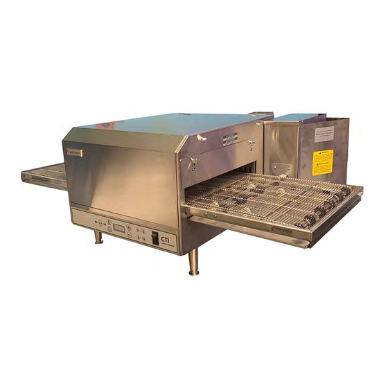
- Page 1 Consistency You Can Count On Digital Countertop Conveyor Oven Series 2500 Domestic and International Service Manual Original Document Document #: LIN_EO_SM_DIGCT_S2500_DOM&INTL_4606010 – 07/21...
- Page 2 Safety Notices Read These Before Proceeding: As you work on Lincoln equipment, be sure to pay close DANGER attention to the safety notices in this manual. Disregarding Do not install or operate equipment that has been the notices may lead to serious injury and/or damage to the misused, abused, neglected, damaged, or altered/ equipment.
-
Page 3: Table Of Contents
Table of Contents Section 1 General Information Model Number Key ......................7 Section 2 Installation Exterior Dimensions – Series 2500 ................... 9 Installation Requirements ....................10 Electrical Code Requirements ......................10 Spacing Requirements ........................10 Ventilation Requirements......................... 10 Installation ........................10 Electrical Grounding Instructions ....................11 Assembly Instructions .....................11 Stacking Instructions .......................12 Mounting Instructions .....................12... - Page 4 Table of Contents (continued) Section 6 Controls Operating Instructions ....................25 Power-Up the Oven ..........................25 Change Belt Direction ........................25 Shutdown ............................... 25 Programming ........................26 Programming the Four Menu Preset Buttons ................26 Programming the Manual Mode ....................26 Programming the Subset Menu ..................... 27 Section 7 Component Procedures Oven Back .........................29...
- Page 5 Table of Contents (continued) Section 9 Diagrams Wiring Schematics ......................37 Model 2500 SN 1606100100720 to SN 2012100100663 ............37 Model 2500 SN 2012100100664 and Above ................38 Models 2501, 2502 ..........................39 Models 2504, 2510..........................40 Model 2505 ............................41 Model 2507.
- Page 6 Table of Contents (continued) THIS PAGE INTENTIONALLY LEFT BLANK Document #: LIN_EO_SM_DIGCT_S2500_DOM&INTL_4606010 – 07/21...
-
Page 7: General Information
Section 1 General Information Model Number Key Example: 2501-000-U-0001620 CUSTOM CONFIGURATION CODE PLATFORM SIZE (i.e. General Market) LANGUAGE CODE MODEL 25 01 – 0 00 – – 00 0 1620 (i.e. Digital Countertop) FINGER SETUP INDICATES VOLTAGE (i.e. 208V, 1 phase, 60 Hz) AGENCY CODE (i.e. - Page 8 General Information Section 1 THIS PAGE INTENTIONALLY LEFT BLANK Document #: LIN_EO_SM_DIGCT_S2500_DOM&INTL_4606010 – 07/21...
-
Page 9: Installation
Section 2 Installation Exterior Dimensions – Series 2500 G*** Inches 51.125 31.10 20.50 17.9375 31.875 18.25 49.75 31.25 18.9375 27.50 (mm) (1298.6) (789.9) (520.7) (455.6) (809.6) (463.6) (1263.7) (793.8) (481.0) (698.5) * A dimension pertains to a unit with standard conveyor and 12" (304 mm) take-off shelves included on each end. ** B dimension pertains to a unit with standard length conveyor. -
Page 10: Installation Requirements
Installation Section 2 Installation Requirements SPACING REQUIREMENTS The oven must have 6 inches (152 mm) of clearance from DANGER combustible surfaces. In case other equipment is located on the right side of oven, a minimum clearance of 24 inches All utility connections and fixtures must be maintained in (609 mm) is required from that equipment. -
Page 11: Electrical Grounding Instructions
Section 2 Installation Assembly Instructions ELECTRICAL GROUNDING INSTRUCTIONS Warning Install legs as shown. Domestic As it pertains to domestic model units, this appliance is equipped with a three-prong (grounding) plug for your protection against shock hazard and should be plugged directly into a properly grounded three-prong receptacle. -
Page 12: Stacking Instructions
Installation Section 2 Stacking Instructions Mounting Instructions FOR SINGLE AND DOUBLE STACK UNITS Position the oven on the countertop and carefully mark the position of the rear legs. Remove the oven from the Important countertop and position the mounting rings so that the large (center) hole is where the legs of the oven were When stacking ovens, be sure to remove the bottom marked. -
Page 13: Installation Checklist
Section 2 Installation Installation Checklist DANGER Check all wiring connections, including factory terminals, before operation. Connections can become loose during shipment and installation. CHECKLIST Are the correct clearances maintained? Is the bottom unit on legs? Are legs fastened to the counter-top with included hardware? ... - Page 14 Installation Section 2 THIS PAGE INTENTIONALLY LEFT BLANK Document #: LIN_EO_SM_DIGCT_S2500_DOM&INTL_4606010 – 07/21...
-
Page 15: Operation
Section 3 Operation Sequence of Operation POWER SUPPLY Electrical Power is supplied to the oven by a three conductor cord set. • Black conductor is HOT. • White conductor is HOT. • Green conductor is ground. Line voltage is supplied through the fuses (F1, F2) and line one (L1) through the manual resettable control box high limit (T1) to the ON/OFF switch, the Cooling Fan Thermostat (T2), the Cool Down Timer (TD), and to the Main Fan Relay (R2). - Page 16 Operation Section 3 THIS PAGE INTENTIONALLY LEFT BLANK Document #: LIN_EO_SM_DIGCT_S2500_DOM&INTL_4606010 – 07/21...
-
Page 17: Maintenance
3. Clean the conveyor belt by wiping with a clean, water- The Lincoln Countertop Impinger® Oven contains electrical dampened cloth to remove any baked on crust or food components. Before cleaning the oven, switch off and product. -
Page 18: Conveyor Removal & Reinstallation
Maintenance Section 4 Conveyor Removal & Reinstallation 3. Reassemble in reverse order. Caution Conveyor and belt may be hot! 1. Remove extension shelves (if applicable). 4. Install extension shelves (if applicable). 2. Push coupling away from drive lugs. Remove conveyor from oven cavity. Document #: LIN_EO_SM_DIGCT_S2500_DOM&INTL_4606010 –... -
Page 19: Finger Removal & Disassembly For Cleaning
Section 4 Maintenance Finger Removal & Disassembly for Cleaning REASSEMBLY 1. Reassemble in reverse order. DISASSEMBLY NOTE: Check to ensure that the holes in the columnating 1. Remove 1/4-20 thumbscrews (2 per panel) then pull plate are lined up with the holes in the orifice panel. back the panel. - Page 20 Maintenance Section 4 THIS PAGE INTENTIONALLY LEFT BLANK Document #: LIN_EO_SM_DIGCT_S2500_DOM&INTL_4606010 – 07/21...
-
Page 21: Troubleshooting
Section 5 Troubleshooting Troubleshooting Guide Problem Cause Correction Oven fan will not run Incoming Power Supply Check circuit breaker, reset if required. Check power plug to be sure it is firmly in receptacle. Measure incoming power, call power company if needed. 5 Amp Fuse and Fuse Holder Check fuse for continuity, replace if necessary. - Page 22 Troubleshooting Section 5 Problem Cause Correction Amber light is on but oven still Elevated temp in Front Panel Clean grease filters on Front Panel and Control Box. Thermostat will working (model 2504 Australia over 140°F open automatically when temp falls below 120°F. only) T5 thermostat is now closed Oven will not heat...
- Page 23 Section 5 Troubleshooting Problem Cause Correction Oven will not heat Cavity High Limit Thermostat Check high limit thermostat (T1) for continuity through switch. Terminals are normally closed, open at 660°F (350°C). If open, push in (Note: Dual voltage ovens only reset button and retest.
- Page 24 Troubleshooting Section 5 Problem Cause Correction Conveyor will not run Control Transformer With the main fan switch (S) on, check for 208/240 VAC at the primary of the transformer. If no voltage is present, check for voltage at the power switch (for Dual Voltage models, also check for voltage through the high limit and voltage select relay).
-
Page 25: Controls
Section 6 Controls Menu Preset Buttons Display Screen Temperature Control Button On/O Switch Belt Direction Button Belt Speed / Time Control Button Digital Display Control Panel POWER-UP THE OVEN Warning 1. Turn the on/off switch to the ON position. The oven Do not work around conveyor with long hair, loose will now run according to the previously programmed clothing, or dangling jewelry. -
Page 26: Programming
Controls Section 6 Programming PROGRAMMING THE MANUAL MODE 1. Press and hold the time and temperature buttons for PROGRAMMING THE FOUR MENU PRESET BUTTONS approximately 5 seconds to enter manual mode. 1. Press and hold the desired menu button (1-4) for approximately 5 seconds. -
Page 27: Programming The Subset Menu
Section 6 Controls PROGRAMMING THE SUBSET MENU There are three settings that can be accessed by an authorized technician: the temperature calibration setting, temperature display (°F or °C) and the conveyor belt direction. (+) and (-) Buttons Temperature Control Button Belt Speed / Time Control Button Step 1... - Page 28 Controls Section 6 THIS PAGE INTENTIONALLY LEFT BLANK Document #: LIN_EO_SM_DIGCT_S2500_DOM&INTL_4606010 – 07/21...
-
Page 29: Component Procedures
Section 7 Component Procedures oven cavity. Warning 4. Disconnect and mark wires from control board Before removing or installing any component in the (red=neg., white=pos.) and remove thermocouple. Digital Countertop Oven, be sure to disconnect all 5. Reassemble in reverse order, keeping junction inside electrical power. -
Page 30: Motor Capacitor
Component Procedures Section 7 Motor Capacitor Air Pump REPLACEMENT REPLACEMENT With Power Off: With Power Off: 1. Remove six (6) screws and remove motor cover and 1. Remove oven back assembly. (See Oven Back Removal) vent piping. 2. Remove main fan. (See Main Fan Replacement) Warning 3. -
Page 31: Conveyor
Section 7 Component Procedures Conveyor Conveyor Sprockets REMOVE OR ADD SECTION OF BELTING REPLACEMENT 1. Locate connecting links on the conveyor belt, turn belt 1. Remove conveyor. See Conveyor above. to place the links on the top left end of the conveyor, 2. -
Page 32: Contactor
Component Procedures Section 7 Contactor Membrane REPLACEMENT REPLACEMENT With Power Off: With Power Off: 1. Remove control box cover. 1. Remove conveyor and side panels. 2. Disconnect wires from contactor. Mark wires for proper 2. Remove screws from ends of control panel and remove reassembly. -
Page 33: Control Box Hi-Limit
Section 7 Component Procedures Control Box Hi-Limit Air Pressure Switch REPLACEMENT REPLACEMENT With Power Off: With Power Off: 1. Remove control box cover. 1. Remove control box cover. 2. Remove wires from hi-limit thermostat. Mark wires for 2. Disconnect tube from air pressure switch. proper reassembly. - Page 34 Component Procedures Section 7 THIS PAGE INTENTIONALLY LEFT BLANK Document #: LIN_EO_SM_DIGCT_S2500_DOM&INTL_4606010 – 07/21...
-
Page 35: Charts
Section 8 Charts Utility Specifications Model No. Motor RPM Input Rate Voltage Amps Phase No. of wires 2500-000 (Dual Volt) 3100 6 kW 208-240 2500-202 (Dual Volt) 1750 6 kW 208-240 2501-000 3100 6 kW 2501-001 (Quiet) 1750 6 kW 2502-000 3100 6 kW... - Page 36 Charts Section 8 THIS PAGE INTENTIONALLY LEFT BLANK Document #: LIN_EO_SM_DIGCT_S2500_DOM&INTL_4606010 – 07/21...
-
Page 37: Wiring Schematics
Section 9 Diagrams Wiring Schematics Model 2500 SN 1606100100720 to SN 2012100100663 Document #: LIN_EO_SM_DIGCT_S2500_DOM&INTL_4606010 – 04/21... -
Page 38: Model 2500 Sn 2012100100664 And Above
Diagrams Section 9 Models 2500 SN2012100100664 and Above Document #: LIN_EO_SM_DIGCT_S2500_DOM&INTL_4606010 – 07/21... -
Page 39: Models 2501, 2502
Section 9 Diagrams Models 2501, 2502 Document #: LIN_EO_SM_DIGCT_S2500_DOM&INTL_4606010 – 07/21... -
Page 40: Models 2504, 2510
Diagrams Section 9 Models 2504, 2510 Document #: LIN_EO_SM_DIGCT_S2500_DOM&INTL_4606010 – 07/21... -
Page 41: Model 2505
Section 9 Diagrams Model 2505 Document #: LIN_EO_SM_DIGCT_S2500_DOM&INTL_4606010 – 07/21... -
Page 42: Model 2507
Diagrams Section 9 Model 2507 Document #: LIN_EO_SM_DIGCT_S2500_DOM&INTL_4606010 – 07/21... -
Page 43: Models 2508, 2509
Section 9 Diagrams Models 2508, 2509 Document #: LIN_EO_SM_DIGCT_S2500_DOM&INTL_4606010 – 07/21... -
Page 44: Model 2512
Diagrams Section 9 Model 2512 Document #: LIN_EO_SM_DIGCT_S2500_DOM&INTL_4606010 – 07/21... -
Page 45: Model 2514
Section 9 Diagrams Model 2514 Document #: LIN_EO_SM_DIGCT_S2500_DOM&INTL_4606010 – 07/21... - Page 46 Notes Document #: LIN_EO_SM_DIGCT_S2500_DOM&INTL_4606010 – 04/21...
- Page 47 Section 9 Diagrams THIS PAGE INTENTIONALLY LEFT BLANK Document #: LIN_EO_SM_DIGCT_S2500_DOM&INTL_4606010 – 07/21...
- Page 48 KitchenCare® aftermarket parts and service. Welbilt’s portfolio of award-winning brands includes Cleveland™, Convotherm®, Crem®, Delfield®, fitkitchen®, Frymaster®, Garland®, Kolpak®, Lincoln®, Manitowoc®, Merco®, Merrychef® and Multiplex®. Bringing innovation to the table • welbilt.com ©2020 Welbilt Inc. except where explicitly stated otherwise. All rights reserved.
Need help?
Do you have a question about the V2500 Series and is the answer not in the manual?
Questions and answers