Lincoln 2500 Series Service & Parts Manual
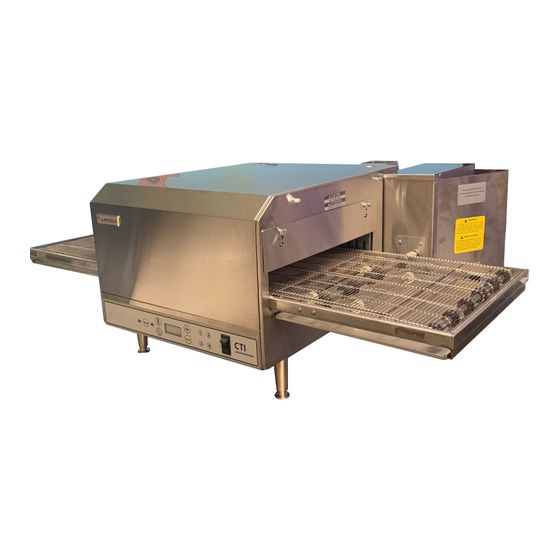
Digital countertop
Hide thumbs
Also See for 2500 Series:
- Domestic and international service manual (48 pages) ,
- Service manual (48 pages) ,
- Installation, operation and maintenance manual (16 pages)
Advertisement
Quick Links
Advertisement

Related Manuals for Lincoln 2500 Series


Summary of Contents for Lincoln 2500 Series
- Page 1 *** Cooling fan - 369378 PARTS & SERVICE MANUAL Digital Countertop Series 2500 REV: 11.2.10 Lincoln Foodservice Products, LLC 1111 North Hadley Road Fort Wayne, Indiana 46804 Telephone: 260.459.8200 Fax: 888.790.8193 Technical Support: 800.678.9511 lincolnfp.com...
-
Page 2: Model Number Key
MODEL NUMBER KEY EXAMPLE: 2501-000-U-0001620 Platform 25 01 - 0 00 - U - 00 0 1620 Size Finger Setup Agency Code (i.e. CE & RoHS combined) Custom Configuration Code (i.e. General Market Version) Language Code Indicates voltage (i.e. 208V, 1 phase, 60 Hz) Model (i.e. - Page 3 DIGITAL DISPLAY CONTROL PANEL DISPLAY SCREEN TEMPERATURE CONTROL BUTTON MENU PRESET BUTTONS BELT DIRECTION BUTTON ON / OFF SWITCH BELT SPEED / TIME CONTROL BUTTON OPERATING INSTRUCTIONS Do not work around conveyor belt with long hair, loose clothing, or dangling jewelry. Getting caught in WARNING: the conveyor belt could result in serious injury! Prior to operating your new countertop oven, it is important to understand the available options.
- Page 4 CHANGE BELT DIRECTION 1. Press the “Belt Direction Button” to change the direction in which the conveyor belt travels. BELT DIRECTION BUTTON PROGRAMMING THE FOUR MENU PRESET BUTTONS 1. Press and hold the desired menu button (1-4) for approximately 5 seconds. The display screen will flash the temperature setpoint.
- Page 5 PROGRAMMING THE MANUAL MODE 1. Press and hold the Time and Temperature buttons for approximately 5 seconds to enter manual mode. Press the Time button to allow for changes in time. Press the (+) or (-) button to reach the desired time. BELT DIRECTION BUTTON BELT SPEED / TIME CONTROL BUTTON...
- Page 6 ACCESSING SUBSET MENU OPTIONS There are three settings that can be accessed by an authorized technician; the temperature calibration setting, temperature display (°F or °C) and the conveyor belt direction. SUBSET MENU INSTRUCTIONS (+) AND (-) BUTTONS TEMPERATURE CONTROL BUTTON BELT SPEED / TIME CONTROL BUTTON STEP ONE...
-
Page 7: Sequence Of Operation
SEQUENCE OF OPERATION Power Supply Electrical Power is supplied to the oven by a three conductor cord set. Black conductor is HOT. White conductor is HOT. Green conductor is ground. Line voltage is supplied through the fuses(F1, F2)and line one(L1) through the manual resettable control box high limit(T1) to the ON/OFF switch, the Cooling Fan Thermostat(T2), the Cool Down Timer(TD), and to the Main Fan Relay(R2). -
Page 8: Schematic Diagram
SCHEMATIC DIAGRAM 2501-000, 2501-001, 2501-002, 2501-003, 2501-008, 2501-009, 2502-000, 2502-001, 2502-002, 2510-000 Digital Countertop Service Manual... - Page 9 SCHEMATIC DIAGRAM 2504-000, 2504-001, 2514-000 Digital Countertop Service Manual...
- Page 10 SCHEMATIC DIAGRAM 2505-000 Digital Countertop Service Manual...
- Page 11 SCHEMATIC DIAGRAM 2508-000, 2509-000, 2512-000, 2512-004 Digital Countertop Service Manual...
-
Page 12: Troubleshooting Guide
TROUBLESHOOTING GUIDE SYMPTOM POSSIBLE CAUSE EVALUATION Oven fan will not run Incoming Power Supply Check circuit breaker, reset if required. Check power plug to be sure it is firmly in receptacle. Measure incoming power, call power co. if needed. 5 Amp Fuse and Fuse Holder Check fuse for continuity, replace if necessary. - Page 13 5 Amp Fuse and Fuse Holder Check fuse for continuity, replace if necessary. Control Box Hi-Limit Check for continuity through the switch(T2). Thermostat Terminals are normally closed and open at 140°F(60°C), if open, reset thermostat and test oven for proper operation. If thermostat will not hold, and control box temperature is not exceeding 140°F (60°C), replace thermostat.
- Page 14 breaker is not open and still no secondary voltage then replace transformer. Solid State Relay Check for 24VAC at terminals A1 and A2 of the Solid State Relay(SSR). If no voltage is present then perform thermocouple checks(Thermocouple type j testing). If thermocouple checks good and still no voltage at terminals A1 and A2 then replace control board.
- Page 15 power switch. If voltage is present at the primary, check for voltage on the secondary side of transformer (24 VAC). If no 24 VAC present on secondary check circuit breaker (CB) on transformer. If still no secondary voltage then replace transformer Digital Control Check for 24 VAC input to the control board at terminals J1 and J2.
- Page 16 REMOVAL, INSTALLATION & ADJUSTMENT GUIDE Oven Back Removal WITH OVEN POWER OFF Remove six (6) nuts and remove motor cover and • vent piping. Disconnect all wiring from motor and heating • element. Remove four (4) nuts holding oven back and •...
- Page 17 Main Fan Removal WITH OVEN POWER OFF Remove oven back assembly. (See OVEN BACK • REMOVAL) Loosen two (2) screws on fan hub and slide fan off • of motor shaft. (Note location of fan on motor shaft for reinstallation is 3/16" (4.5 mm) from back wall.) Reinstall in reverse order and check system •...
- Page 18 NOTE: Be certain to replace insulation seal when oven back is re-installed (pn.369470). Conveyor To remove or add section of Belting Locate connecting links on the conveyor belt, turn • belt to place the links on the top left end of the conveyor, approximately 8”...
-
Page 19: General View
GENERAL VIEW LETTER PART NUMBER DESCRIPTION 340038 Switch, Lighted Rocker See Membrane Switch Assembly Section in this Manual See Cavity Assembly Section in this Manual See Rear Wall Assembly Section in this Manual 370020 Motor Cover Assembly 370041 Duct, Inner/Outer Assembly 370102 Cap, Flue Bottom 369453... - Page 20 MEMBRANE SWITCH ASSEMBLY LETTER PART NUMBER DESCRIPTION 70001558 Bracket 4070541 Stand-Off 10001209 10-32 x ¾ self-clenching 371109 Control Board 10004756 Membrane Switch with Buttons (All models except 2501-002 and 2502-002) 371108 Membrane Switch with Buttons (Models 2501-002 and 2502-002 only) Digital Countertop Service Manual...
- Page 21 CAVITY ASSEMBLY LETTER PART NUMBER DESCRIPTION 90000140 Cover Panel Assembly, Left Side 70001559 Cover, Front / Top 90000142 Cover Panel Assembly, Right Side 369495 Conveyor Baffle 370656 Lower Air Duct Panel (all models except 2501-002 & 2502-002) 370655 Lower Air Duct Panel (models 2501-002 & 2502-002 only) 370913 Top Air Duct Panel (all models except 2501-002 &...
-
Page 22: Control Box
CONTROL BOX LETTER PART NUMBER DESCRIPTION 369413 Key, Square Drive 369460 Compression Spring 350259 Screw, THMSS 6-32 x 3/8 369410 Coupling Sleeve 70001433 Plate, Reinforcement 369953 Flat Washer 70002100 Fan Cover 370749 Strain Relief 370364 Ground Lug 371154 EMI Filter (models 2512-000, 2512-004, 2508-000, 2509-000, 2509-F06) 371157 EMI Filter (models 2504-000, 2504-001, 2505-000, 2514-000) 357067... - Page 23 CONTROL BOX VIEW Digital Countertop Service Manual...
- Page 24 CONTROL PANEL ASSEMBLY MODELS 2501-000, 2501-010, 2501-001, 2501-002, 2501-003, 2502-000, 2502-001, 2502-002, 2510-000 LETTER PART NUMBER DESCRIPTION 370732 Transformer 70002102 Mounting Plate 370551 Rail, MDI Relay 370739 Contactor 371038 50A SSR 370466 Module, Time Delay, 230V 369422 Relay 369431 Hi-Limit, Control Box 369507 Cooling Fan Thermostat Digital Countertop Service Manual...
- Page 25 CONTROL PANEL ASSEMBLY MODEL 2514-000 LETTER PART NUMBER DESCRIPTION 371038 50A SSR 369507 Cooling Fan Thermostat 370732 Transformer 70002102 Mounting Plate 370117 Terminal Block, 5 Pole 9002882 Terminal Bracket Assembly 371158 EMI Capacitor 370740 Rail, Contactor 370739 Contactor 370466 Module, Time Delay, 230V 369422 Relay 369430...
- Page 26 CONTROL PANEL ASSEMBLY MODELS 2512-000, 2512-004, 2509-F06 LETTER PART NUMBER DESCRIPTION 10004413 25A SSR, 3PH 369507 Cooling Fan Thermostat 370732 Transformer 70002102 Mounting Plate 370740 Rail, Contactor 9002882 Terminal Bracket Assembly 371155 EMI Capacitor 370117 Terminal Block, 5 Pole 370739 Contactor 370466 Module, Time Delay, 230V...
- Page 27 CONTROL PANEL ASSEMBLY MODELS 2508-000, 2509-000 LETTER PART NUMBER DESCRIPTION 10004413 25A SSR, 3PH 369507 Cooling Fan Thermostat 370732 Transformer 70002102 Mounting Plate 370740 Rail, Contactor 9002882 Terminal Bracket Assembly 371155 EMI Capacitor 370117 Terminal Block, 5 Pole 370739 Contactor 370466 Module, Time Delay, 230V 369422...
- Page 28 CONTROL PANEL ASSEMBLY MODELS 2504-000, 2504-001, 2505-000 LETTER PART NUMBER DESCRIPTION 371038 50A SSR 369507 Cooling Fan Thermostat 370732 Transformer 70002102 Mounting Plate 370740 Rail, Contactor 9002882 Terminal Bracket Assembly 371158 EMI Capacitor 370117 Terminal Block, 5 Pole 370739 Contactor 370466 Module, Time Delay, 230V 369422...
- Page 29 This page intentionally left blank. Digital Countertop Service Manual...
- Page 30 OVEN BACK ASSEMBLY LETTER PART NUMBER DESCRIPTION 369418 Heating Element, 208V, 1PH 369419 Heating Element, 240V, 1PH 369450 Heating Element, 220V, 1PH 369456 Heating Element, 380V, 1PH 369476 Heating Element, 220V, 3PH 369477 Heating Element, 240V, 3PH 370105 Heating Element, 400V, 1PH 370165 Heating Element, 230V, 3PH 370409...
- Page 31 OVEN BACK ASSEMBLY VIEW Digital Countertop Service Manual...
- Page 32 STANDARD CONVEYOR LETTER PART NUMBER DESCRIPTION 369443 Complete Standard Conveyor Assembly (31” length) 369462 Idler Axle 369515 Drive Sprocket 369516 Conveyor Bearing 369463 Drive Axle 369471 Roll Pin, 5/32 x 7/8” 1343 Entry Shelf, 12” 1344 Entry Shelf, 4” 369412 Conveyor Splice Clip 369411 Conveyor Belting...
- Page 33 EXTENDED CONVEYOR LETTER PART NUMBER DESCRIPTION 369909 Complete Extended Conveyor Assembly (49 ¾” length) 369462 Idler Axle 369515 Drive Sprocket 369516 Conveyor Bearing 369463 Drive Axle 369471 Roll Pin, 5/32 x 7/8” 369943 Conveyor Frame, Extended 369412 Conveyor Splice Clip 369481 Conveyor Belting –...
- Page 34 This page intentionally left blank. Digital Countertop Service Manual...
- Page 35 This page intentionally left blank. Digital Countertop Service Manual...
- Page 36 Digital Countertop Service Manual...
Need help?
Do you have a question about the 2500 Series and is the answer not in the manual?
Questions and answers