
Related Manuals for THOMSON grass valley XtenDD


Summary of Contents for THOMSON grass valley XtenDD
- Page 1 XtenDD DIGITAL PRODUCTION SWITCHERS Planning and Installation Revision 1 Document Order Number: RU 0070 / 000 212 350 500 Printed: Oct 2004 the most watched worldwide...
- Page 2 This document and any updates and/or supplemental information, including any copies thereof, cannot be reproduced, neither communicated to a third party, without written authorization from THOMSON Broadcast and Media Solutions. Please notify THOMSON Broadcast and Media Solutions of any errors in this document. We also would appreciate any comments you have to improve this manual.
- Page 3 Number: 510057.001 The Quality System of: Thomson Broadcast & Media Solutions TBMS TBMS 400 Providence Mine Road 17 rue du Petit Albi-BP 8244 Nevada City, CA 95945 95801 Cergy Pontoise Cergy, France TBMS Weiterstadt, Germany TBMS Brunnenweg 9 10 Presidential Way, 3...
- Page 4 Safety Instructions SAFETY INSTRUCTIONS Safety regulations production switcher is designed in conformity with the safety regula- tions EN60950 / VDE0805 (protection class 1) and is in an unobjectionable condi- tion when leaving the factory. Information on the following pages provides important safety guidelines for Opera- tors and Service Personnel.
- Page 5 Safety Instructions ATTENTION! Electrostatic sensitive devices on the p.c. board. Observe the following pre- caution instructions for handling! Earthing connection Never remove or insert p.c. boards when the production switcher is switched on. Install or remove p.c. boards from the production switcher with the corresponding equipment only.
- Page 6 Safety Instructions CAUTION! To reduce the risk of electric shock, plug each power supply cord into sepa- rate branch circuits employing separate service grounds. When setting up and connecting the switcher, connect the external earth line al- ways before connecting the power line. Thus is ensured that in case of a short-circuit between mains and case, the voltage is led to earth.
- Page 7 The EMC regulations are only applicable when correctly shielded cables are used for the installation of the equipment. This applies to video cables as well as control cables. Corresponding cables can be obtained from Thomson. Run all connection cables in covered cable ducts (risk of stumbling).
- Page 8 Sicherheitshinweise SICHERHEITSHINWEISE Sicherheits- Produktionsmischer entspricht den Sicherheitsbestimmungen von bestimmungen EN60950 / VDE 0805 (Schutzklasse 1) und hat das Werk in sicherheitstechnisch einwandfreiem Zustand verlassen. Um diesen Zustand zu erhalten und einen gefahrlosen Betrieb sicherzustellen, sind die nachfolgenden und die in den einzelnen Abschnitten des Handbuches auf- geführten Sicherheitshinweise, insbesondere die Hinweise bezüglich Brandge- fahr, elektrischer Schlag und Verletzungsgefahren, zu beachten: Achtung:...
- Page 9 Sicherheitshinweise ACHTUNG! Auf den Platinen befinden sich elektrostatisch empfindliche Teile. Beachten Sie bei der Handhabung folgende Vorsichtsmaßnahmen: Earthing connection Niemals Leiterplatten entfernen oder einsetzen wenn der Mischer eingeschal- tet ist. Leiterplatten aus dem Mischer nur mit entsprechender Ausrüstung entneh- men. Vor Entnahme der Leiterplatten aus dem Schutzbeutel, geerdetes Hand- gelenkband anlegen (z.B.
- Page 10 Sicherheitshinweise Beim Aufstellen und Anschließen des Mischers ist die Verkabelung einer externen Erdleitung immer vor der Verkabelung der Netzleitung vorzunehmen. Hiermit wird gewährleistet, daß im Falle eines Kurzschlusses zwischen Netz und Gehäuse die Spannung gegen Erde abgeleitet wird. Daher die Erdleitung niemals während des Betriebes vom Gerät lösen.
- Page 11 Die EMV-Bestimmungen werden nur eingehalten, wenn bei der Installation der Ge- räte vorschriftsmäßig abgeschirmte Kabel verwendet werden. Dies gilt sowohl für Video- als auch für Steuerkabel. Entsprechende Kabel sind bei Thomson erhält- lich. Sämtliche Anschlußkabel in abgedeckten Kabelschächten verlegen (Stolper- gefahr).
-
Page 12: Table Of Contents
Contents CONTENTS General Overview Family ......... 1 - 1 Panel Overview . - Page 13 Contents Installing Panels ..........3 - 23 3.5.1 Single Module Mounting...
- Page 14 Contents Initial Installation Installation Check List ......... . . 5 - 1 Power-up of the Switcher Devices .
- Page 15 Contents 6.3.4 Operationg Hints ..........6 - 31 Installing External Devices Digital Video Effect System Integration...
- Page 16 Contents VTR Control ........... . 7 - 43 7.2.1 Sony BVW75 VTR Protocol...
- Page 17 Contents Planning and Installation - Rev. 0 / 04.2002...
-
Page 18: General
1. General GENERAL OVERVIEW FAMILY Configuration overview RPS35-x Control Panel Basic Mainframe + Options = XDM- 4 - BM RPS35-4LX XDM- 3 - BM XDM- 2 - BM M/E 1 M/E 2 M/E 1 M/E 3 M/E 2 RPS35-4L M/E 1 3 M/E + P/P 2 M/E + P/P 1 M/E + P/P... - Page 19 1. General KEY FEATURES Seven RU high mainframe Up to 4 M/E stages Up to 90 Inputs Up to 36 Inputs Up to 20 Aux Busses 4 Dynachrome Chroma Keyers per M/E and up to 8 DSKs in P/P Machine Control Internal 4 channel DVE (delivering 3D planar effects) Internal RAM Recorder (providing 32 seconds of internal clip store)
-
Page 20: Panel Overview
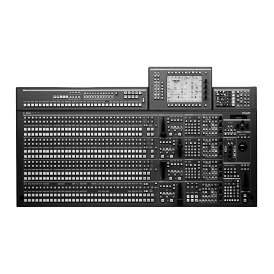
1. General PANEL OVERVIEW 1.3.1 RPS35-2S CONTROL PANEL The production switcher panel RPS35-2/S with one mixing level M/E and one Pro- gram/Preset, as well as the touch screen display panel. Fig. 101: Control panel RPS35-2S Panel Order number RPS35-2S Control panel (OnAir normal lighting) 000 351 860 510 RPS35-2S-HL Control panel (OnAir highlighting) -
Page 21: Rps35-2 Control Panel Set
1. General 1.3.2 RPS35-2 CONTROL PANEL SET The production switcher panel set RPS35-2 comprises the basic unit RPD35-2 with one mixing level M/E and one Program/Preset, as well as the stand-alone display panel RPV35-4TS. The mnemonics for P/P and Make Memo Aux are standard. Fig. -
Page 22: Rps35-3 Control Panel Set
1. General 1.3.3 RPS35-3 CONTROL PANEL SET The production switcher panel set RPS35-3 comprises the RPD35-3 with two mix- ing levels M/E and one Program/Preset, the display panel RPV35-4TS, the wipe panel RPW35-3/-4 and the aux panel RPA35-3. The mnemonics for P/P, Make Memo and Aux are standard. Fig. - Page 23 1. General Options Order number RC 2148 Emergency Hard Disk Drive IDE, min. 000 351 745 000 2 GB. Must be ordered initially together with basic panel. Operating Software pre-configured. RC 2376 Redundant Power Supply 000 351 774 600 Initial order only. RC 2380 Operating System Windows NT for PC 000 351 775 800...
- Page 24 1. General 1.3.4 RPS35-4/32 CONTROL PANEL SET The production switcher panel set RPS35-4/32 comprises the RPD35-4/32 with three mixing levels M/E and one Program/Preset, the display panel RPV35-4TS, the wipe panel RPW35-3/-4 and the aux panel RPA35-4/32. The redundant power supply and input mnemonics are standard. Fig.
- Page 25 1. General Options Order number RC 2840 Mounting frame set 000 351 854 000 RC 2148 Emergency Hard Disk Drive IDE, min. 000 351 745 000 2 GB. Must be ordered initially together with basic panel. Operating Software pre-configured. RC 2380 Operating System Windows NT for PC 000 351 775 800 1 - 8...
-
Page 26: Networking
1. General NETWORKING The networking of panels and mainframe is at the core of the concept of the production switcher system. The ability to connect multiple panels to one main- frame, or to connect multiple mainframes to one panel, opens up many new possi- bilities. - Page 27 1. General OVERALL BLOCK DIAGAM VIDEO 1 - 10 Planning and Installation - Rev. 0 / 04.2002...
- Page 28 1. General 90 EXTERNAL SIGNALS INTERNAL SIGNALS OUTPUT MODULE RY 3404 ME 1 EQUAL WIPE PROCESSOR BUFFER BUFFER BUFFER BUFFER WHITE KEY 1 BUFFER BUFFER KEY 2 KEY 3 KEY PROCESSOR BUFFER BUFFER KEY 4 EQUAL KEY 5 BUFFER BUFFER CLEAN INPUT MODULE BUFFER...
- Page 29 1. General 1 - 12 Planning and Installation - Rev. 0 / 04.2002...
-
Page 30: Technical Data
2. Technical Data TECHNICAL DATA MAINFRAME 2.1.1 INPUTS Number & format Up to 90 inputs ITU - R 656, 270 Mbit/s Return loss 5 - 270 MHz > 15dB Autophasing range: approx. 22 ms Asynchronous signals: Can be switched Reference signal BNC, 0.3V sync, black - burst or CCVS 1 BNC digital, serial ITU - R 656, 270 Mbit/s Cable lenght... -
Page 31: Power Supply
2. Technical Data 2.1.4 POWER SUPPLY Optional redundant power supply Line voltage 100V - 240V AC " 10% Line frequency 50Hz/60Hz " 5% Power consumption Max. 700 W (mainframe) Touch (leakage) currents < 2.5 mA (for each power supply) 2.1.5 MECHANICAL DATA Dimensions mainframe 19”... -
Page 32: Control Panels
2. Technical Data CONTROL PANELS 2.2.1 POWER SUPPLY 1 power module LPQ 250 standard or LPQ 350 (in RPS35 - 4/32) 1 redundant power module LPQ 250 (LPQ 350) optional Line voltage 100 V to 240 V AC $10 %, autosense Line current 2.5 A max (RPS 35 - 2/3) 3.5 A max (RPS 35 - 4) - Page 33 2. Technical Data 2 - 4 Planning and Installation - Rev. 0 / 04.2002...
-
Page 34: Mounting Instructions
3. Mounting Instructions MOUNTING INSTRUCTIONS GENERAL SAFETY INSTRUCTIONS Caution! These instructions are for use by qualified personnel only. To reduce the risk of electric shock, do not perform any installation other than that contained in the Mounting Instructions unless you are qualified to do so. Refer all servi- cing to qualified service personnel. -
Page 35: Mounting The Mainframe
3. Mounting Instructions MOUNTING THE MAINFRAME 3.2.1 UNPACKING Your equipment may be shipped in several different boxes, depending upon order size and configuration. Check the contents of each box against the packing list to ensure your order is com- plete. If equipment is missing or damaged, contact the shipping company immedi- ately. -
Page 36: Mechanical Dimensions
3. Mounting Instructions 3.2.2 MECHANICAL DIMENSIONS mainframe of the switcher is located in a closed 19-inch frame which houses the individual plug-in cards of the video and control electronics as well as the power supply units. 17.6” = 447 mm 12.2”... -
Page 37: Mounting Into A Cabinet
Earth connection is essential before connecting supply voltage! For details see chapter Technical Data. For installation, Thomson optionally provides a 19-inch cabinet with recommended mounting accessories. When using cabinets of other manufacturers, observe the respective mounting instructions. -
Page 38: Ventilation Mainframe
3. Mounting Instructions VENTILATION MAINFRAME The ambient temperature during operation must not fall below + 5 °C or exceed + 40 °C (41 °F to 104 °F). Optimum operation is ensured at an ambient temperature of 20 °C. The mainframe is ventilated by the fan unit (8 fans) being mounted at the left side in the mainframe. - Page 39 3. Mounting Instructions 3 - 6 Planning and Installation - Rev. 0 / 04.2002...
-
Page 40: Mounting The Control Panels
3. Mounting Instructions MOUNTING THE CONTROL PANELS 3.4.1 UNPACKING Your equipment may be shipped in several different boxes, depending upon order size and configuration. Check the contents of each box against the packing list to ensure your order is complete. If equipment is missing or damaged, contact the shipping company im- mediately. -
Page 41: Mechanical Dimensions
3. Mounting Instructions Software package: Mouse CD-ROM XtenDD software CD-ROM Intel PII Bus Master Device Drivers CD-ROMs Microsoft Windows 95 package 3.5” Diskette Microsoft Setup Boot Disk 3.5” Diskette Philips Ethernet Link Driver 3.5” Diskettes Philips WGE10 Utilities (2 disks) Motherboard documentation Accessory pack 002 351 740 051: Locking tool for sub-panels... - Page 42 3. Mounting Instructions 3.4.3 REMOTE CONTROL PANEL RSAT1 Cut-out dimensions: 245 x 118 mm Planning and Installation - Rev. 0 / 04.2002 3 - 9...
- Page 43 3. Mounting Instructions 3.4.4 REMOTE CONTROL PANEL RSAT2 25.8 114.5 482.6 19” Mounting Frame 465.1 All dimensions are [ mm ] 3 - 10 Planning and Installation - Rev. 0 / 04.2002...
- Page 44 3. Mounting Instructions Desk Cut-out for Remote Panel RSAT2: Cut-out dimensions: 441 x 217 mm Planning and Installation - Rev. 0 / 04.2002 3 - 11...
- Page 45 3. Mounting Instructions 3 - 12 Planning and Installation - Rev. 0 / 04.2002...
- Page 46 3. Mounting Instructions 3.4.5 RPS35-2/S CONTROL PANEL FRONT 1084 LEFT 314.5 43.3 Please keep free for service working! Keep free for cabling! 1058 Note! All measurements are [mm]. 1080 Tolerance +/- 0,2 1084 Planning and Installation - Rev. 0 / 04.2002 3 - 13...
- Page 47 3. Mounting Instructions TOUCHSCREEN DISPLAY OF THE RPS35-2S PANEL 298.5 278.5 44.5 311.5 314.5 Attention! When separating the display from the control panel, D the EMV protection is not ensured any longer (radiation is also possible via the cables) D the ESD protection is not ensured any longer (damage to electronic components is possible) D the UL and other permissions are not applicable any longer Note! D warrenty is not ensured any longer...
-
Page 48: Rps35-2 Control Panel Set
3. Mounting Instructions 3.4.6 RPS35-2 CONTROL PANEL SET FRONT LEFT Mechanical dimensions see next page. 1364 Keep free for cabling! Note: There are two possibilities of mounting Display Module RPV35-2. 3. Mounting the display module with the mounting frame outside the switcher into the control desk or wall. - Page 49 3. Mounting Instructions RPV35-2 STAND-ALONE DISPLAY PANEL Ç Ç 20.4 mounting plate 4 max 15.23 164.25 3 - 16 Planning and Installation - Rev. 0 / 04.2002...
-
Page 50: Rps35-3 Control Panel Set
3. Mounting Instructions 3.4.7 RPS35-3 CONTROL PANEL SET FRONT LEFT 202.1 1390 184.6 163.3 1364 Keep free for cabling! Note All measurements are [mm]. Tolerance +/- 0,2 1386 1390 Planning and Installation - Rev. 0 / 04.2002 3 - 17... -
Page 51: Rps35-4/32 Control Panel Set
3. Mounting Instructions 3.4.8 RPS35-4/32 CONTROL PANEL SET FRONT LEFT 202.1 1602 184.6 163.3 1576 Keep free for cabling! Note All measurements are [mm]. Tolerance +/- 0.2 1598 1602 3 - 18 Planning and Installation - Rev. 0 / 04.2002... -
Page 52: Desk Cut-Out For Rps35-2/S
3. Mounting Instructions 3.4.9 DESK CUT OUT FOR RPD35-2S 1060 Cut - out measurements Note All measurements are [mm]. legend Cut - out module edge Planning and Installation - Rev. 0 / 04.2002 3 - 19... -
Page 53: Desk Cut-Out For Rps35-2
3. Mounting Instructions 3.4.10 DESK CUT OUT FOR RPS35-2 1366 1390 Cut - out measurements Note All measurements are [mm]. legend Cut - out module edge 3 - 20 Planning and Installation - Rev. 0 / 04.2002... -
Page 54: Desk Cut-Outs For Rps35-3
3. Mounting Instructions 3.4.11 DESK CUT-OUTS FOR RPS35-3 701 0 346 0 1366 Cut - out measurements for panels with 1390 ”All-in-One” Mounting Frame RC 2360 Cut - out measurements for single module mounting Note All measurements are [mm]. legend Cut - out module edge Planning and Installation - Rev. -
Page 55: Desk Cut-Outs For Rps35-4/32
3. Mounting Instructions 3.4.12 DESK CUT-OUTS FOR RPS35-4/32 1578 Cut - out measurements for panels with ”All-in-One” Mounting Frame RC 2840 1602 Cut - out measurements for single module mounting Note All measurements are [mm]. legend Cut - out module edge 3 - 22 Planning and Installation - Rev. -
Page 56: Installing Panels
3. Mounting Instructions INSTALLING PANELS WARNING! With the standard modules installed, the main panel weights 50 kg (110 lbs). During installation and until secured in the desk, use an appropriate lifting device to lift and support the main panel. Failure to follow this precau- tion can result in injury to personnel and damage to equipment. -
Page 57: Single Module Mounting
3. Mounting Instructions 3.5.1 SINGLE MODULE MOUNTING Note: There are two possibilities of mounting Display Module RPV35-2. 1. Mounting the display module with the mounting frame outside the swit- cher into the control desk or wall. See below. 2. Stand-alone display with rigid stand. The stand has to be mounted on the control panel in the place provided for this purpose, between Aux and Wipe panel. -
Page 58: Mounting With "All-In-One" Mounting Frame
3. Mounting Instructions 3.5.2 MOUNTING WITH “ALL-IN-ONE” MOUNTING FRAME Trace careful the position of panel on the desk. The exact dimensions of the main panel and the side panels you can find in section “Desk cut-outs”. Cut-out the opening in the desk. Unpack each individual piece. - Page 59 3. Mounting Instructions Put in the extended main panel in the cutout. For fastening, bores are provided in the frame. The frame can be fastened with countersunk wood screws with a diameter of 4 mm. The length of the screw depends on the plate thickness of the desk.
-
Page 60: Ventilation Panels
3. Mounting Instructions VENTILATION PANELS During operation, the ambient temperature in the desk must not fall below 5 °C and not exceed 35 °C. For supply air and exhaust air, ventilation slots are provided in the lower control panel part. In order to ensure continuous air circulation, make sure that the ventila- tion slots are not covered when mounting the control panel! Note: The control panel must not be mounted into closed desks! - Page 61 3. Mounting Instructions 3 - 28 Planning and Installation - Rev. 0 / 04.2002...
-
Page 62: Connection And Startup
4. Connection and Startup CONNECTION AND STARTUP GROUNDING REQUIREMENTS Protective grounding Grounding of the device serves the product safety and meets the requirements of Class I equipment. The device is connected with the protective earth of the power supply circuit (e.g. the studio) by means of the mains cable which also contains the earthed protective conductor PE. -
Page 63: Connecting Power And Earth Lines
4. Connection and Startup CONNECTING POWER AND EARTH LINES The units of the Production Switcher have been completely checked in the factory and are in conformity with the safety regulation EN60950 / VDE0805 / UL 1419 (Class 1 equipment) when leaving the factory. CAUTION! To reduce the risk of electric shock, plug each power supply cord into sepa- rate branch circuits employing separate service grounds. - Page 64 4. Connection and Startup CONTROL PANEL CONNECTORS 4.3.1 RPS35-2S CONTROL PANEL Caution: Do not remove any cover. Risk of electrical shock. High current level. Caution: See installation manual before Caution: This unit has two power cords. To prevent electric shock disconnect both power This device complies with part 15 of the No user serviceable parts inside.
- Page 65 4. Connection and Startup 4.3.1.1 Connection of a PS2 keyboard to the RPS35 - 2S control panel IInstead of an USB keyboard a PS2 keyboard can be also attached.The PS2 keyboard should be connected a short time for configuration purposes only. In normal operation mode the panel must be closed. red coding The PS2 keyboard can be connected by using the provided adapter.
- Page 66 4. Connection and Startup 4.3.1.2 Power Supply Connectors Item Socket / Connector Socket type Function Description Connector type AC Power in 1 IEC-320, CEE-22 Convenience outlet for power supply to the control panel. Molex DC 12V / 2A max for power connector Aux- Auxiliary DC out MiniFit junior 2 pin panel.
- Page 67 4. Connection and Startup 4.3.1.3 Controller Connectors Item Socket / Connector Socket type Function Description Connector type J17 LAN BNC / 50-ohms Alternatly to J18 Cheapernet LAN connector for connection to panel PC and mainframe controller or further LEDs LAN devices. Activ For further information see the section ”LAN Power...
- Page 68 The following USB mice have been tested and released for being used with the RPS35-2S panel: USB mouse no. 1801.1062 from Roline (included in the delivery) It can be ordered from the THOMSON multimedia in Weiterstadt/Germany under the order no. 003 119 100 322. Logitech, Model M-BA 47 It can be purchased on the special market.
- Page 69 4. Connection and Startup 4 - 8 Planning and Installation - Rev. 0 / 04.2002...
- Page 70 4. Connection and Startup 4.3.2 RPS35-2 / RPS35-3 AND RPS35-4/32 CONTROL PANELS Connection Panel 1, RC 2375 Power Supply for Control Panels RPS35-2 and RPS35-3 RC 2810 Power Supply for Control Panel RPS35-4/32 Caution: Do not remove any cover. Risk of electrical shock. High current level. Caution: See installation manual before Caution: This unit has two power cords.
- Page 71 4. Connection and Startup 4 - 10 Planning and Installation - Rev. 0 / 04.2002...
-
Page 72: Control Panel Connectors
4. Connection and Startup 4.3.2.1 Power Supply Connectors Item Socket / Connector Socket type Function Description Connector type AC Power in 1 IEC-320, CEE-22 Convenience outlet for power supply to the control panel. RPS35- 4 (3.5A max) RPS35- 3/2 (2.5A max) Molex DC 12V / 2A max for power connector Aux- Auxiliary DC out... -
Page 73: Controller Connectors
4. Connection and Startup 4.3.2.2 Controller Connectors Item Socket / Connector Socket type Function Description Connector type J17 LAN BNC / 50-ohms Alternatly to J18 Cheapernet LAN connector for connection to panel PC and mainframe controller or further LEDs LAN devices. Activ For further information see the section ”LAN Power... -
Page 74: Pc Connectors
4. Connection and Startup 4.3.2.3 PC Connectors Item Socket / Connector Socket type Function No.: Description Connector type 5-pin Mini DIN Possibility to connect a PS2 Mouse to the inter- PS2 Mouse round connector nal Pentium PC. female 9-pin subminiature Serial RS232 interface for internal connection to COM 2 D-connector... - Page 75 4. Connection and Startup 4 - 14 Planning and Installation - Rev. 0 / 04.2002...
-
Page 76: Wipe Panel Connectors
4. Connection and Startup 4.3.2.4 Wipe Panel Connectors DC POWER IN WIPE SELECTION Item Socket / Connector Socket type Function Description Connector type DC POWER IN 3-pin D-type DC output (+5V) for Wipe side panel. female Connected with DC POWER OUT on the Main panel. - Page 77 4. Connection and Startup 4.3.2.5 Display Panel Connector RPV35-4TS for (RPS35-4/32 HL, RPS35-3 and RPS35-2) Panel Link Input Touch screen control Item Socket / Connector Socket type Function Description Connector type Panel Link Input 26-pin D-type Serial data from COM1, panel link data for TFT- female Display.
-
Page 78: Aux Panel Connectors
4. Connection and Startup 4.3.2.6 Aux Panel Connectors DC POWER IN AUX SELECTION Item Socket / Connector Socket type Function Description Connector type DC POWER IN 3-pin D-type DC input (+5V) for Aux panel. female Connected with DC POWER OUT on the Main panel. - Page 79 4. Connection and Startup 4 - 18 Planning and Installation - Rev. 0 / 04.2002...
-
Page 80: Panel Set Rps35-2
4. Connection and Startup PANEL INTER-UNIT CABLING Display Panel Connector 4.4.1 PANEL SET RPS35-2 PANEL LINK INPUT TOUCH SCREEN CONTROL Panel link cables for Touch screen control cables: standard version display: Cable 1.8m, order no. 5 136 391 008 Cable RC 2146 1m, order no. 0 351 744 800 Cable 6.0m, order no. -
Page 81: Panel Set Rps35-3 / Rps35-4/32
4. Connection and Startup 4.4.2 PANEL SET RPS35-3 / RPS35-4/32 Display Panel Connector Wipe Panel Connectors AUX Panel Connectors PANEL LINK INPUT TOUCH SCREEN CONTROL DC POWER IN AUX SELECTION DC POWER IN WIPE SELECTION Panel link cable RC 2146 1m, Touch screen control cables: Cable set RC 2144 (1.2m) Cable set RC 2144 (1.2m) - Page 82 4. Connection and Startup 4.4.3 NEW IPC WITH MODIFIED CONNECTION UNIT With the control panel serial numbers listed below, the connection unit of the side panel PC (IPC) will be modified: Control Panel RPS35 - 2 Serial No xxx and higher Control Panel RPS35 - 3 Serial No xxx and higher Control Panel RPS35 - 4/32...
- Page 83 4. Connection and Startup Cable adapter for Mouse and Keyboard connection. 4 - 22 Planning and Installation - Rev. 0 / 04.2002...
-
Page 84: Mounting The Panel Link Cable
4. Connection and Startup 4.4.4 MOUNTING THE PANEL LINK CABLE Angle bracket for Angle bracket for Panel Link Output J1 Panel Link Input For stabilizing the plug connections of the panel link cable, the connectors have to be fixed by corresponding angle brackets. The angle brackets are supplied to- gether with the panel link cable and have to be mounted and screwed as shown above. -
Page 85: Overview
4. Connection and Startup MAINFRAME CONNECTORS 4.5.1 OVERVIEW The Basic Mainframes are equipped with the following modules: Basic Mainframe Board/Module XMD - 2 - BM XMD - 3 - BM XMD - 4 - BM RC 3304 Fan Unit RY 3470 Power Supply Unit RY 3156 Controller* RY 3081 Genlock* RY 3441 Input Processor... - Page 86 4. Connection and Startup Serial Output 1 - RC 3450 Serial Input 1 - RC 3420 Serial Input 2 - RC 3421 Serial Input 3 - RC 3422 Serial Input 4 - RC 3423 Serial Input 5 - RC 3424 Serial Output 2 - RC 3451 Serial Output 3 - RC 3452 Control Module - RC 3455...
- Page 87 4. Connection and Startup 4 - 26 Planning and Installation - Rev. 0 / 04.2002...
-
Page 88: Connector Descriptions
4. Connection and Startup 4.5.2 CONNECTOR DESCRIPTIONS 4.5.2.1 AC Power, Grounding Item Socket / Connector Socket type Description No.: Designation Connector type M4 threaded pins Terminal screw for additional unit earthing AC POWER IN 1 + 2 IEC-320, CEE-22 Convenience outlet for power supply to the mainframe. - Page 89 4. Connection and Startup 4.5.2.2 Video Inputs Item Socket / Connector Socket type Description No.: Designation Connector type Input 1 ... 18 BNC / Serial Comp Maximum of 90 switcher main inputs . ITU-R 656 Input 19 ... 36 In the basic version, the upper module (Inputs 1 ...
- Page 90 4. Connection and Startup 4.5.2.3 Video Outputs Item Socket / Connector Socket type Description No.: Designation Connector type PGM 0 BNC / Serial Comp Output Module 1 PGM 0 ITU-R 656 PVW 0 Outputs for M/E1 and P/P stage. CLEAN 0 M/E1 PGM 1 10 additional switcher outputs via...
- Page 91 4. Connection and Startup 4.5.2.4 Control Connectors Item Socket / Connector Socket type Description No.: Designation Connector type J 152 ALARM BNC / 75 ohms Alarm connector. Specification SMPTE 269M Pin assignment: Center +ALARM Shield - ALARM For details refer to section 4.7 below. J153 BNC / Serial Comp SD serial composes reference video...
-
Page 92: Lan Interface, Audio Interface
4. Connection and Startup 4.5.2.5 LAN Interface, Audio Interface Parts of delivery: 50 W Terminator BNC T-type connector Item Socket / Connector Socket type Description No.: Designation Connector type J 6 LAN BNC / 75 ohms Cheapernet connector for connection to control panel and panel PC or further LAN devices. -
Page 93: Dc In / Dc Out
4. Connection and Startup 4.5.2.6 DC In /DC Out Item Socket / Connector Socket type Description No.: Designation Connector type J 3 DC IN 9-pin D-type External supply to back up the internal 6...8V / 300mA female stores if power failed. J 3 DC OUT 9-pin D-type For future use... -
Page 94: Pin Assignments
4. Connection and Startup PIN ASSIGNMENTS Panel link output Signal not used not used T x 0 (+) TFT display data serial T x 0 ( - ) T x 1 (+) T x 1 ( - ) T x 2 (+) T x 2 ( - ) T x C (+) TFT display data clock... - Page 95 4. Connection and Startup PORT RS-232 Signal Chassis Ground Transmit Data Receive Data not used Signal Ground not used 9-pin D-type Clear to Send female Request to Send not used A standard RS232 cable 1:1 is required for connection to a PC. PORT RS-422/485 Signal Bus Contr...
- Page 96 4. Connection and Startup AUDIO IN/OUT Signal Signal Ground Audio In 1 ( - ) Audio In 2 (+) Signal Ground Audio In 3 ( - ) Audio In 4 (+) Signal Ground Audio Out 1 ( - ) Audio Out 2 (+) 25-pin D-type Signal Ground male...
- Page 97 4. Connection and Startup GPI/GPO Signal Panel GPI In 6+ GPI In 5+ GPI In 4+ GPI In 3+ GPI In 2+ GPI In 1+ GPI Out 6 GPI Out 5 GPI Out 4 GPI Out 3 GPI Out 2 25-pin D-type GPI Out 1 female...
- Page 98 4. Connection and Startup DC OUT Signal max 2.5A Chassis Ground 12V_GND 12V_GND 12V_GND 12V_GND 9-pin D-type male Planning and Installation - Rev. 0 / 04.2002 4 - 37...
- Page 99 4. Connection and Startup GPI / GPO Signal Mainframe Chassis Ground GPI Out 2 GPI Out 3~ Chassis Ground GPI Out 6 GPI Out 7~ Chassis Ground GPI In 1 - GPI In 3+ GPI In 4 - GPI In 5 - GPI In 7+ GPI In 8 - 14 - 17...
-
Page 100: Alarm Specification
4. Connection and Startup ALARM SPECIFICATIONS Specification according to SMPTE 269M: The standard describes a simple interface over which television equipment can be report the occurrence of internal failures and faults in incoming signals. It is in- tended for use in all television equipment, from the simple active devices to the most complex. - Page 101 4. Connection and Startup 4 - 40 Planning and Installation - Rev. 0 / 04.2002...
-
Page 102: Cheapernet Characteristics
4. Connection and Startup LAN SPECIFICATIONS For operation of the production Switcher, multiple mainframes and panels designed for different applications can be connected and operated via a Local Area Network (LAN). Caution: The switchers are real-time devices. Other devices connected to the same LAN cabling will cause degradation in communica- tions and reduce the reliability of the Switcher. - Page 103 4. Connection and Startup Cheapernet connection cable Kv 770 (50-ohms coax) Maximum length per segment = 150 m, Minimum length per segment = 0.5 m Longer distances are possible with a repeater, i.e. each repeater provides a fur- ther segment with an extension of up to 150 m 10 units per segment at maximum.
-
Page 104: Network Configuration
4. Connection and Startup 4.8.2 NETWORK CONFIGURATION Mainframe, main panel and panel PC are network devices using TCP-IP protocol. The devices are shipped with default cheapernet IP addresses; however, as more resources are attached to the network, addresses must be changed. Default address ranges for the devices: 192.168.0.1... - Page 105 4. Connection and Startup 4 - 44 Planning and Installation - Rev. 0 / 04.2002...
-
Page 106: Initial Installation
5. Initial Installation INITIAL INSTALLATION WARNING! The control panels and mainframe do not contain any control elements or switches required for operation of the switcher. For this reason, the control panel should not be opened by unauthorized persons and should always be locked. - Page 107 5. Initial Installation Establish cheapernet cabling between control panel and mainframe. Connect the video input and output cables as well as the other control cables. ATTENTION! Cheapernet has to be terminated with a 50-Ω resistor at each end! Connect the mains cable to the central mains distribution of the studio and switch on power.
-
Page 108: Power-Up Of The Switcher Devices
5. Initial Installation POWER-UP OF THE SWITCHER DEVICES Note: The switchers are not provided with a central power switch. Switching on and off is made via the central mains distribution of the studio or the equipment cabinet! For service works plug out the power cables of the mainframe and the control panel. -
Page 109: Mainframe Overview
5. Initial Installation MAINFRAME OVERVIEW É É É É FX PROC RY 3460 É É É É É É É É RY 3410 M/E1 PROC É É É É É É É É RY 3410 É É É É PROC É... - Page 110 5. Initial Installation É É É É RY 3460 É É É É É É É É M/E1 RY 3410 É É É É É É É É RY 3410 É É É É É É É É Input INPUT RY 3441 É...
-
Page 111: Front View With Led's And Control Elements
5. Initial Installation 5.3.1 CONTROLLER RY 3156 5.3.1.1 Front View with LED’s and Control Elements LEDs VCC OK 4.95 V G1 - G5 VBAT FAIL TEMP FAIL ALARM Reset Test Diagnostic SLAVE ERROR G6 + G7 INIT FAIL J6 + J7 VCC Test Point GND Test Point Reset... - Page 112 5. Initial Installation 5.3.1.2 P.C. Board with Control Elements RY 3156 R11 R12 SIMM SIMM EQUIP GPI Config FLASH Front parts EPROM see figure above FLASH EPROM BATT SIMM SIMM SIMM SIMM EQUIP EQUIP Planning and Installation - Rev. 0 / 04.2002 5 - 7...
- Page 113 5. Initial Installation Pos. Function Factory adjust. LED green VCC OK, norm=on LED red <4.95V, norm=off LED red VBAT FAILure (Battery defective) LED red TEMP FAILure (temp to high) LED red ALARM, norm=off Reset RSE processor Test program RSE processor LED red SLAVE ERROR, norm=off (lit during Reset an HW test)
- Page 114 5. Initial Installation Pos. Function Factory adjust. T5/T27 DIL switches (high byte) (T5 = RSE, T27 = Host): 0 = execute startup script 1 = do not execute startup script 0 = start normal 1 = start verbose 0 = normal boot 1 = boot via LAN not used not used...
- Page 115 5. Initial Installation GPI Configuration The sliding switches T6, T8, T11, T13, T15, T18, T21 and T25 on the controller board RY 3156 are assigned to the GPI inputs 1...8 (general-purpose inputs). These inputs are provided with optocouplers. The switches enable to match the inputs to different control concepts: Switch in position”1”...
-
Page 116: Genlock Ry 3081
5. Initial Installation 5.3.2 GENLOCK RY 3081 RY 3081 P3V3 MP5 GND LCA_DONE - 5V missing SYNC ERR SER SD SER HD ANALOG REF FCTRL MP10 MP11 MP12 /BLD MP13 TPD DOWNLOAD MP14 TPC MP16 TPB PROGRAMMER INTERFACE MP17 TPA Planning and Installation - Rev. - Page 117 5. Initial Installation Pos. Function Factory adjustment LED green: LCA configuration o.k. LED yellow: -5V supply (VEE or VEE1) down (on board DC/DC converter) LED yellow: synchonization error display - should be off. LED green: serial SDTV serial digital input detected. If flashing, valid input detected but not selected.
-
Page 118: Fx Processor Ry 3460
5. Initial Installation 5.3.3 Fx Processor RY 3460 RY 3460 P3V3 P1V8 MP5 GND TEMP ERROR DONE 3.3V ERROR 1.3V ERROR 1.8V ERROR RS232 LED-LINE DSP RESET Pos. Function Factory adjustment Temperatur eError: LED on: Over temperature LED green on: LCA_DONE When lit this LED shows the successfull locking of all FPGAs... -
Page 119: M/E Processor Ry 3410
5. Initial Installation 5.3.4 M/E PROCESSOR RY 3410 RY 3410 MP13 P3V3 MP14 P1V9 MP12 P1V5 TEMP ERROR DONE 1.3V ERROR 1.5V ERROR RS232 LED-LINE DSP RESET Pos. Function Factory adjustment Temperatur eError: LED on: Over temperature 1.3V Error: LED on: Undervoltage 1.5V Error: LED on: Undervoltage LED green on:... - Page 120 5. Initial Installation 5.3.5 INPUT PROCESSOR RY 3441 RY 3441 +3V3 M32 P3V M18 GND LCA_DONE TEMP_ERROR 3V_ERROR J103 PROGRAMMER INTERFACE Pos. Function Factory adjustment LED green on: LCA_DONE LCA firmware is loaded correctly. LED yellow on: TEMP_ERROR temperature exceeds maximum level. LED yellow on: 3V_ERROR 3.0V power supply is out of order.
-
Page 121: Mounting The Input Processor Board Ry 3441
5. Initial Installation 5.3.5.1 Mounting the Input Processor Board RY 3441 The special design of the plug contacts on the Input Processor Board RY 3441 requires additional force of power when mounting. By means of the PCB Assembly/Insertion Tool, board RY 3441 can be easily and safely installed into the mainframe. - Page 122 5. Initial Installation 5.3.6 AUX PROCESSOR RY 3430 RY 3435 RY 3435 RY 3435 RY 3435 P3V3 P1V5 M7 VEE1 Aux 16 - 20 Aux 11 - 15 Aux 6 - 10 Aux 1 - 5 LCA_DONE 1.5V_ERROR RY 3435 RY 3435 RY 3435 DOWNLOAD...
- Page 123 5. Initial Installation 5.3.7 CONTROLLER RY 3490 5.3.7.1 General The new mainframe controller board is designed to fit into the XtenDD series pro- duction switchers (SD) in a backwards - compatible fashion. NOTE! This controller is not usable in the DD35 mainframe! The new mainframe controller board also incorporates the Genlock processor, which was a separate board in the XtenDD mainframe.
- Page 124 5. Initial Installation 5.3.7.2 Front View with LED’s and Control Elements LAN LEDs Green LED: Link Yellow LED: Activity PS2 Interface (Keyboard) Genlock LEDs LED 1: Serial SD LED 2: Serial HD PS2 Interface (Mouse) LED 3: Sync_Error VGA Interface Status LEDs LED 1: VCC LAN LEDs...
- Page 125 5. Initial Installation 5.3.7.3 GPI Configuration The sliding switches T12 ... T19 on the controller board RY 3490 are assigned to the GPI inputs 1...8 (general-purpose inputs). These inputs are provided with opto- couplers. The switches enable to match the inputs to different control concepts: Switch in position”1”...
-
Page 126: Control Panel Overview
5. Initial Installation CONTROL PANEL OVERVIEW 5.4.1 FADER CONNECTOR PANEL RC 1855 The faders in the control panels are each provided with connector panel RC 1855 which establishes the connection to controller RY 1821. A 4-step DIP switch (T1) on the connector panel determines the input channel of the 12-bit A/D converter. On each of these connector panels, exactly one switch has to be set to ON, the other switches have to be switched OFF! Assignment is as follows:... - Page 127 5. Initial Installation 5.4.2 PANEL CONTROLLER RY 2370 RY 2370 ZL/ZH GPI6 GPI5 GPI4 GPI3 GPI2 GPI1 INT KOAX T10 T11 T12 T13 SIMM 1 INT COAX EXT AUI SIMM 2 EXT AUI G9 G10 EDRAM EPROM FLASH CLK ADJ Battery M18 M1 VCC GND...
- Page 128 5. Initial Installation Pos. Function Factory adjust. G31...46 Status LEDs LED red 4.95V LED green VCC OK LED red VBATT LOW LED red INIT FAIL LED red BOOT ERROR LED red DRAM ERROR LED red LAN ACC LED yellow BSC PROG LED yellow BSC TEST LED yellow...
- Page 129 5. Initial Installation 5.4.3 PANEL CONTROLLER RY 2100 RY 2100 GPI6 GPI5 GPI4 GPI3 GPI2 GPI1 EPROM FLASH BATT SIMM 1 PC RESET PC POWER FAIL SIMM 2 M16 M17 J25 J26 J27 VCC GND LAN ADDRESS HIGH TEST RESET OPER ON/OFF FLASH...
- Page 130 5. Initial Installation Pos. Function Factory adjust. G3...18 Status LEDs LED red 4.95V not OK, norm=off LED green VCC OK, norm=on LED red VBAT FAILure (Battery defective) LED red INIT FAILure, norm=off LED red HOST ERROR, norm=off LED yellow LAN ACCess, blinking LED red TEMP FAILure (temp too high) LED yellow BSCAN (factory: BSCAN OK)
- Page 131 5. Initial Installation GPI Configuration The sliding switches T2 ... T7 on the controller board RY 2100 (T8 ... T13 on controller board RY 2370) are assigned to the GPI inputs 6 ... 1 (general-purpose inputs). These inputs are provided with optocouplers. The switches enable to match the inputs to different control concepts: Switch in position”1”...
-
Page 132: Timing / Genlock Alignment
5. Initial Installation TIMING / GENLOCK ALIGNMENT (IN PREPARATION) When source signals are fed into the switcher, it must be ensured that the time dif- ference between the sources is not outside the operating range of the internal swit- cher autophasers (XtenDD = 22 µs). The output signals of the sources must corre- spond to the timing customary in operation. - Page 133 5. Initial Installation Timing reference diagram XtenDD ( - 3) Min delay approx 41 us approx 0.8 us Autophasing range input Aux outputs approx 22 us approx 10 us ME1 outputs, PVW approx 10 us ME2 output, PVW approx 10 us PP / ME3 outputs, PVW approx 10 us Total timing position of XtenDD in respect to the reference input...
- Page 134 5. Initial Installation Timing reference diagram XtenDD ( - 4) Min delay approx 41 us approx 0.8 us Autophasing range input Aux outputs approx 22 us ME1 outputs, PVW approx 10 us ME2 output, PVW approx 10 us ME3 output, PVW approx 10 us Main outputs, PVW approx 10 us...
-
Page 135: Genlock Adjustment
5. Initial Installation 5.5.1 GENLOCK ADJUSTMENT The mixers include the possibility to perform the genlock adjustment of the individ- ual input sources in Install E-Box menu. When adjusting the genlock phase, all sources have to be successively checked for their timing by switching up on the bus Aux1. To adjust the genlock phase, select the softkey in the Install E-Box menu and se- lect the index card Timing. - Page 136 5. Initial Installation The bar diagram shows the timing of the input source relatively to the autophasing range. All sources should be timed between the two marker lines in the middle area of the bar. The right line (with the respective switcher type name) marks the earliest mixer input (latest timing of the sources).
- Page 137 5. Initial Installation 5 - 32 Planning and Installation - Rev. 0 / 04.2002...
- Page 138 5. Initial Installation Planning and Installation - Rev. 0 / 04.2002 5 - 33...
-
Page 139: Installing System Accessories
Jupiter from THOMSON. For that optional hardware device the already existing Tally Distributor MI-3040 was chosen. This device is driven via the serial MPK protocol and has 40 opto-isolated inputs and 40 relay outputs. - Page 140 6. Installing System Accessories The Tally Inputs of the Tally Boxes for Yellow Tally are NOT scanned, because Yel- low Tally is a function of Red Tally and the switchers state (Next Transition, PST Source etc.). A Tally Box is installed in the menu Install Mainframe / Tally. For each box its 4-Byte MPK address must be given.
- Page 141 6. Installing System Accessories Planning and Installation - Rev. 0 / 04.2002 6 - 3...
-
Page 142: Tally Installation Menu
6. Installing System Accessories 6.1.3 TALLY INSTALLATION MENU Index card for selecting Tally ports (e.g. port 5) and setting the MI-3040 box ad- dresses (e.g. 30001e5). 6.1.4 PIN ASSIGNMENT Each Pin # - as printed on the rear side of the MI-3040 - has three screwing clamps (A, B and G). - Page 143 6. Installing System Accessories Tally Out Input 07 Tally Out Input 08 Tally Out Input 09 Tally Out Input 10 Tally Out Input 11 Tally Out Input 12 Tally Out Input 13 Tally Out Input 14 Tally Out Input 15 Tally Out Input 16 Tally Out Input 17 Tally Out Input 18...
- Page 144 6. Installing System Accessories Function Second MI-3040 Tally Out Input 33 Tally Out Input 34 Tally Out Input 35 Tally Out Input 36 Tally Out Input 37 Tally Out Input 38 Tally Out Input 39 Tally Out Input 40 Tally Out Input 41 Tally Out Input 42 Tally Out Input 43 Tally Out Input 44...
- Page 145 6. Installing System Accessories Function Third MI-3040 Tally Out Input 49 Tally Out Input 50 Tally Out Input 51 Tally Out Input 52 Tally Out Input 53 Tally Out Input 54 Tally Out Input 55 Tally Out Input 56 Tally Out Input 57 Tally Out Input 58 Tally Out Input 59 Tally Out Input 60...
-
Page 146: Tally Inputs
6. Installing System Accessories 6.1.4.2 Tally Inputs Function Tally In Main Tally In M/E 1 Tally In M/E 2 Tally In M/E 3 Tally In Clean Tally In Clean M/E 1 Tally In Clean M/E 2 Tally Ready Tally In Aux 1 Tally In Aux 2 Tally In Aux 3 Tally In Aux 4... -
Page 147: Monitor Tally Aux1-15
6. Installing System Accessories 6.1.5 MONITOR TALLY OPERATION 6.1.5.1 Monitor Tally Main / M/E1-3 / Clean The monitoring tally outputs ‘MonTallyMain’, ‘MonTallyM/E1..3’ and ‘MonTally- Clean’ are returning the tally state of the corresponding stage. Example: The M/E2 has got OnAir at ‘Tally In M/E2’. Thus M/E2 is on Air and returns ‘OnAir at MonTally M/E2’. -
Page 148: Tally Ready Input
6. Installing System Accessories 6.1.6 TALLY READY INPUT The Tally ready function is used to generate an internal OnAir signalization without using external tally wiring. Two cases are imaginable: No tally protocol is installed within the environment settings: In this case, the TallyOverAll itself assumes PP/PGM-RED is OnAir and it gen- erates only this default tally for its panels. - Page 149 6. Installing System Accessories The relay selected for this design is an optically-coupled solid-state relay Optoelectronic (PVD1352 by International Rectifier) capable of switching from 0 to 100 volts (AC relays or DC) at up to 300 mA. Each relay may be configured by slide switch for normally- open or normally-closed operation.
- Page 150 6. Installing System Accessories DIP Switch Assignment Switch Relay Switch Relay Switch Relay Switch Relay Switch Relay S1 - 1 S2 - 1 S3 - 1 S4 - 1 S5 - 1 S1 - 2 S2 - 2 S3 - 2 S4 - 2 S5 - 2 S1 - 3...
-
Page 151: Aux Control Panels
The CP-300 and CP-330 control panel modules are basic single bus controllers. 24 inputs are provided with the CP-300 and 48 inputs are provided with the CP-330 panel. Delegation buttons provide access to 6 different busses. THOMSON CP-300 Control Panel 48-source selection button panel with 6 delegation buttons. Mechanical dimen- CP-330 sions: 19”, 1RU, small buttons. - Page 152 6. Installing System Accessories All Aux control panels are “MPK Bus” devices. The panels sit on our message-per- Panel keystroke “MPK Bus” for control panel communication. This serial data bus can Communications support up to sixteen 300-series panels daisy-chained on a single serial port of the switcher mainframe or control panel.
- Page 153 6. Installing System Accessories Connection Examples Control Panel RS422 RS422 standard cable Port 9 pin D female MPK device 1 CP-300 / CP-330 MPK device 2 CP-300 / CP-330 MPK device 9 CP-300 / CP-330 CP-3020 MPK device 10 Expansion Module 1 CP-3021 Expansion Module 2 CP-3021...
-
Page 154: Installation
6. Installing System Accessories 6.2.2 INSTALLATION In the installation procedure, the system is told about the installed panels. This is a hardware setup. 6.2.2.1 Installation E-Box To install up to four AUX-CPs on the E-Box, the following setup menu is used: →... -
Page 155: Installation Panel
6. Installing System Accessories Port opens a pop-up window with all ports plus ”None” like in all other menus where a port must be configured. Note: The port must be different to the ports used for DVEs, Editors, ext. DSKs, etc. MPK Address opens the typewriter pop-up window. -
Page 156: Configuration
6. Installing System Accessories 6.2.3 CONFIGURATION In the configuration procedure, the system is told about the specific func- tion an AUX-CP should perform. This may vary between production types e.g. in one production, the AUX-CP #1 controls AUX Bus 1 in another it controls external AUX bus #10. -
Page 157: Config Panel
6. Installing System Accessories 6.2.3.2 Config Panel → ← ↑ ↓ Movement of the marker. Cursor Movement of the marker. Digipot Opens a pop-up window with the functions that can be programmed. Modify - - - no function this button is used as 2 button i.e. - Page 158 6. Installing System Accessories TiM/E Memo n this button delegates the AUX-CP to register recall for the given TiM/E Memo system. Make Memo this button delegates the AUX-CP to Make Memo macro recall. Note: This function is not available for AUX-CPs installed at the E-Box At least one function other than - - - , 2 or 3...
-
Page 159: Input Assign (Internal Sources)
6. Installing System Accessories 6.2.3.3 Input Assign (Internal Sources) The procedure for input assignment is very similar to the input assignment for the control panel. None all buttons are assigned to no input. Reset Assign Default sets the factory default input assign (see table below) Like ALL sets the input assign like the input assign for bus row ALL (control panel only) - Page 160 6. Installing System Accessories Factory Default Assign Button Blck in01 in02 in03 in04 in05 in06 in07 in08 in09 in10 in11 in12 in13 in14 in15 in16 in17 in18 in19 in20 in21 in22 in23 in24 in25 in26 in27 in28 in29 in30 in31 in32 in33 in34...
- Page 161 6. Installing System Accessories 6.2.4 OPERATION Pressing a delegation button delegates the AUX-CP to that function. The delega- Delegation tion button is lit to indicate that status. If possible, the source buttons show the cur- rent status of the delegated function. In most cases, this will be the selected cross- point on the delegated bus.
- Page 162 6. Installing System Accessories 6 - 24 Planning and Installation - Rev. 0 / 04.2002...
-
Page 163: Under Monitor Displays
6. Installing System Accessories UNDER MONITOR DISPLAYS 6.3.1 GENERAL Thomson offers a wide range of programmable 8-character Under Monitor Dis- plays, especially designed for use in Production Switcher applications and in Jupiter Control Systems for indication of source names and Tally. Single, double and triple displays are available. -
Page 164: Installation
Attention: The EMV regulations are only applicable when correctly shielded cables are used for the installation. This also applies to video cables as well as control cables. Appropriate cables can be obtained from THOMSON. UMD Connection Mainframe Mainframe RS422 Port RS422 standard cable max. - Page 165 6. Installing System Accessories RS422 Cable Mainframe RS422 (Port1 - Port10) 9-pin male 9-pin male D subminiature D - subminiature Shielding Pin 1 - Ground Pin 1 - Ground Pin 2 - RXret Pin 2 - TXret Pin 3 - TX Pin 3 - RX Pin 4 - Ground Pin 4 - Ground...
-
Page 166: Configuration
6. Installing System Accessories 6.3.3 CONFIGURATION Each display can be configured by the user and assigned to the following Display Assignment input/output interfaces: INPUTS 1 ... 90 MAIN OUTPUT ME1 ... PP PVW OUTPUT ME1 ... PP PGM BUS ME1 ... PP PST BUS ME1 ... - Page 167 6. Installing System Accessories The configuration can be done in the Install E-Box menu. Enter the Config data The following parameters are permissible: Reset Set the display assignment to default values. Set Port Select the serial port you like to use. Valid values: 1...10 (RS422 ports 1..10) or 0 to disable UMD handling = none.
- Page 168 6. Installing System Accessories Display 1 / 2 / 3 Assign The following table shows the relationship between the 32 devices and the 96 displays: Display Device RP1 UMD RP2 UMD RP3 UMD single right display right display left display middle display left display single...
- Page 169 6. Installing System Accessories 6.3.4 OPERATING HINTS Please note the following display modes: 8-digit source name preset in the respective menu. If ”Name Transfer” is selected, Inputs the display shows the 4-digit source names. INPUT 1 ... 48 The display will give all information about the video components on the output. Main Output MAIN OUT The output is in Fade To Black mode.
- Page 170 6. Installing System Accessories The display will give all information about the video components on the output. Preview Output PVW OUT If the output shows the transparent input 10: The input name will be shown (see Inputs). ⇑ character is blinking “BGND”...
- Page 171 6. Installing System Accessories The input name of the selected input will be shown (see Inputs). PGM Bus, PST Bus, KEY fill, KEY key, AUX outputs, DVE key, DVE video The timecode of the connected VTR’s will be displayed VTR Timecode The current timecode is 01:20:05:23.
- Page 172 6. Installing System Accessories 6 - 34 Planning and Installation - Rev. 0 / 04.2002...
-
Page 173: Installing External Devices
7. Installing External Devices INSTALLING EXTERNAL DEVICES DIGITAL VIDEO EFFECT SYSTEM INTREGRATION 7.1.1 SCITEX A-5100 DVEOUS 7.1.1.1 DVE Effect Loop Operation For realization of special production effects such as “Flying Key”, the pro- duction Switcher can be connected together with the Effect System A-5100 DVEous from SCITEX. -
Page 174: Interface A-5100 Dveous To
7. Installing External Devices The basic system offers fully functionable DVE system as “twin channel” with two DVE channels and additional background channel with frame store for processing two 4:2:2 video signals independent of each other. This enables processing 2x Video signals or 1x Video with 1x Key with separate Key Shadow in addition to a background signal. -
Page 175: Installation
The EMV regulations are only applicable when correctly shielded cables are used for the installation. This also applies to video cables as well as control cables. Appropriate cables can be obtained from THOMSON. Depending on the configuration, the following connections are required: Video cable... - Page 176 7. Installing External Devices Selecting the A53D VTR Protocol on the DVEous will automatically configure the Control Cable DVE Control associated port in RS232 mode. Thus, on the side one of the RS232 ports will have to be used (Mainframe Port11 - Port14, recommended Port11 or Port12). Note: Although the protocol DVEous may be selected on any of the 15 DD35 ports, only the RS232 ports can be used since the...
- Page 177 7. Installing External Devices The Aux Bus control requires an RS422 cable (connector/connector) with standard Control Cable assignment. The standard RS422 cable is assigned as follows: DVE AUX Bus Control A-5100 mainframe DVEous Mainframe AUX Port RS422 (Port1 - Port10) 9-pin male 9-pin male D subminiature...
-
Page 178: Setup And Port Configuration Of A-5100 Dveous
7. Installing External Devices 7.1.1.6 Setup and Port Configuration of A-5100 DVEous The “DVE Effect Loop” operation requires in the A-5100 the following settings: 1. Press Remote Enable in the System menu. 2. Press Editor to highlight it (but do not switch Editor on) and adjust: Protocol: A53D/VTR BAUD:... - Page 179 7. Installing External Devices Press onto Input of the Channel Menus and select Type: AUX Bus: Press to select onto a channel button(1A,1B,2A or 2B) of the Channel select menu and choose a crosspoint (XPNT). The crosspoint is the inputsource of the switcher which will be switched from remote onto the previous selected AUX Bus.
-
Page 180: Setup And Port Configuration Of The
7. Installing External Devices 7.1.1.7 Setup and Port Configuration of the The operation “DVE Effect Loop” and the “Aux Bus control” requires in the switcher the following settings (for each DVE No.): Menu: INSTALL / E-BOX / DVE In the DVE menu the following settings have to be carried out: DVE No.: 1 and/or 2 Port (RS232):... -
Page 181: Tally Signaling
7. Installing External Devices 7.1.1.8 Tally Signaling The DVEous offers a so-called ”intelligent” tally. This means that it is signalled which of the input signals is part of the output signal. When the input signals of the DVEous come from a switcher’s AUX bus an appropriate setup and cab- ling can be made to provide the correct on air tally signalization. - Page 182 7. Installing External Devices Video Cabling: Cable example 1 Single channel Video + Key Outputs: DVEous Inputs: Video CH1 A CH1 B Ref Term Genlock Inputs: Outputs: Input X Aux n (Video) Aux m (Key) Input Y Tally Cabling: +5V Source GPI Out Aux Video CH1 A...
- Page 183 7. Installing External Devices Video Cabling: Cable example 2 Two channel Video + Key Outputs: Inputs: DVEous CH1 A Video CH1 B Ref Term CH2 A CH2 B Genlock Outputs: Inputs: Aux n Video Input x Aux m Key Input y Aux x Video Aux y Key Tally Cabling:...
- Page 184 7. Installing External Devices Cable example 3 Control cabling DVEous Control Panel Port Chassis special DVEous cable Port CP DVEous Mainframe Port Editor Port Aux Control Cable Control Cable DVE Control DVE Aux Bus Control RS232 RS422 Port 11, Port Port 1, Port 10 Mainframe 7 - 12...
-
Page 185: Questech Charisma Ten-X
7. Installing External Devices 7.1.2 QUESTECH CHARISMA TEN-X 7.1.2.1 DVE Control For the QuesTech Charisma TEN-X, the switcher provides two protocols for differ- ent purposes. The protocols are: 1. Selection and control of DVE-effects: protocol DVE CHARIS 2. Control of AUX-busses by TEN-X: in preparation Planning and Installation - Rev. - Page 186 7. Installing External Devices Control Cable Connection Software TEN-X software version: Mainframe Version 1.16 b Requirements Control Panel Version 2.16 b Connection cable RS-422 cable with male and female connector from a Port 1 ... 10 to TEN-X’s Video Display Unit Editor port. Editor Port Rear panel Video Display Unit VDU...
- Page 187 7. Installing External Devices Setup and Port Configuration of the The operation requires in the mixer the following settings (for each DVE No.): Menu: INSTALL / E-BOX / DVE In menu the following settings have to be carried out: DVE No.: 1 and/or 2 Port: 1 to 10 (RS422)
- Page 188 7. Installing External Devices Setup and Configuration of the TEN-X The operation requires in the Ten-X the following settings: Port: TEN-X VDU EXT CONTROLLER Protocol: BVW75 (w/o ballistics) - Press REMOTE button and toggle Softkey B until “BVW75” is displayed. - Set TIMECODE hours=0 in GENERAL / ENGINEER menu.
-
Page 189: Questech Charisma X-Vtl
7. Installing External Devices 7.1.3 QUESTECH CHARISMA X-VTL The system integration is tested with the Charisma X-VTL software version V3.0.5.4 (July 1999). No scaling of the DVE effects required. 7.1.3.1 DVE Control Controlling the QuesTech Charisma X-VTL unit from the switcher requires the software component DS 0113 to be installed on the flash disk of the RSE com- puter (/flash/appli). - Page 190 7. Installing External Devices Control Cable Connections Software Charisma X-VTL software version V3.0.5.4 Requirements Connection cable Connect the EDIT CONTROL IN connector on the rear panel of the Charisma X-VTL mainframe to one of the RS422 ports of the mainframe (ports 1...10).
- Page 191 7. Installing External Devices Setup and Port Configuration of the The operation requires in the mixer the following settings (for each DVE No.): Select the DVE index card in the menu INSTALL / E-Box and setup the following items: PORT: Setup the port number to which the Chrarisma mainframe is connected to (Port 1...10)
-
Page 192: Switcher And Aux Bus Control
7. Installing External Devices Operation Hints Sequence Recall: DVE sequences may be recalled from the wipe selection panel when dele- gated to DVE1/2 or from the sidepanel DVE1/2 menus, respectively. Tape Motion Controls: The Charisma X-VTL sequence can be controlled by the motion control keys in the machine control section of the control panel (or from the DVE1/2 sidepanel menu, respectively). - Page 193 7. Installing External Devices 7.1.3.3 Control Cable Connections Software Charisma X-VTL software version V3.0.5.4 (July 1999) Requirements Connection cable Connect the SOURCE SELECT OUT connector on the rear panel of the Charisma X-VTL mainframe to one of the RS422 ports of the mainframe (ports 1...10).
- Page 194 7. Installing External Devices Setup and Port Configuration of the Aux bus control protocols for external DVEs are usually being selected within the DVE filecard in the INSTALL / E-Box menu. The Control Type popup menu will show a list of all available protocols for this purpose. However, since the DS 0111 is a dedicated editor protocol rather than a DVE source select protocol it will not show up the DVE context.
- Page 195 7. Installing External Devices Operation Hints Since this protocol is basically an editor protocol, the Edit Enable function on the must be active (i.e. enabled) in order to allow for aux bus switching. In order to establish communication with the switcher the Charisma will periodically send a “wake-up sequence”.
- Page 196 7. Installing External Devices 7 - 24 Planning and Installation - Rev. 0 / 04.2002...
-
Page 197: Pinnacle Dvextreme
7. Installing External Devices 7.1.4 PINNACLE DVEXTREME 7.1.4.1 General For the Pinnacle DVExtreme, the switcher provides two protocols for different pur- poses. The protocols are: 1. Selection and control of DVE-effects: protocol DVExtreme 2. Control of AUX busses by DVExtreme: in preparation Planning and Installation - Rev. -
Page 198: Connection For Selection And Control Of Effects
7. Installing External Devices 7.1.4.2 Connection for Selection and Control of Effects Software DVExtreme Version 1.6 (or higher) Requirements Connection cable Standard RS-422-cable with male-male connector from a Port 1 ... 10 to DVExtrems remote control port RS422-A. MENU OUTPUTS RS422-A Editor Port... -
Page 199: Tally Cabling
7. Installing External Devices 7.1.4.3 Tally Cabling On-air tally outputs are not being supported by the DVExtreme software V1.6. On-air tally outputs will be supported from DVExtreme software V2.0 on. Planning and Installation - Rev. 0 / 04.2002 7 - 27... -
Page 200: Setup And Port Configuration Of The
7. Installing External Devices 7.1.4.4 Setup and Port Configuration of the As well as configuring the DVEXtreme correctly it is important to configure the correctly. Install EBox Menu To set- up the firstly select the INSTALL menu followed by the EBOX sub- menu and then the DVE tab. - Page 201 7. Installing External Devices DVE Setup Menu The DELAY setting is how many fields the waits after a DVE effect is fin- ished before taking the DVE out of the loop. The setting for this depends on the DVE model (the time spent to process serial control commands).
-
Page 202: Setup And Port Configuration Of The Dvextreme
7. Installing External Devices 7.1.4.5 Setup and Configuration of the DVExtreme Remote Menu This installation note will show the correct set- up of the Pinnacle DVEXtreme and . The configuration of the remote protocol is straightforward but re- quires some operational knowledge of both pieces of equipment. On the DVEXtreme select the REMOTE menu by holding down SHIFT and press- ing SET- UP, the menu is shown above. - Page 203 An improved version mixer interface will be available with DVExtreme software V2.0. Scaling of sequences is then no longer required. Sequences with arbitrary length may be used for DVE transitions. This requires the THOMSON software ver- sion DS0114.200 to be installed on the Note: DVExtreme software V2.0 is backwards compatible with V1.6 with regard to the...
-
Page 204: Sony Digital Multi Effect Dme 7000
7. Installing External Devices 7.1.5 SONY DIGITAL MULTI EFFECT DME 7000 7.1.5.1 general For the Sony Digital Multi Effect DME-7000, the switcher provides two protocols for different purposes. The protocols are: 1. Selection and control of DVE-effects: protocol SONY_DME 2. Control of AUX-busses by DME-7000: in preparation 7 - 32 Planning and Installation - Rev. -
Page 205: Connection For Selection And Control Of Effects
7. Installing External Devices 7.1.5.2 Connection for Selection and Control of Effects Software Controlling the DME-7000 unit from the switcher requires the software Requirements component DS0115 to be installed on the flashdisk of the RSE computer (”/flash/ appli”). The DS0115.100 (or higher) device driver software requires soft- ware release V1.40 (or higher).The DME unit requires software version V3.06 (or higher). -
Page 206: Tally Cabling (In Preparation)
7. Installing External Devices 7.1.5.3 Tally Cabling (in preparation) 7.1.5.4 Setup and Port Configuration of the The operation requires in the mixer the following settings (for each DVE No.): Menu: INSTALL / E-BOX / DVE In menu the following settings have to be carried out: DVE No.: 1 and/or 2 Port:... -
Page 207: Setup And Configuration Of The Sony Dme-3000
7. Installing External Devices 7.1.5.5 Setup and Configuration of the SONY DME-3000 In the DME SETUP menu (page #700) press the required function key to select the OPERATION menu (page #702). Setup DME protocol for the EDITOR PORT 7.1.5.6 Operation Hints Sequence Recall: DME sequences may be recalled from the wipe selection panel when... -
Page 208: Control Cable Connections
7. Installing External Devices 7.1.5.8 Control Cable Connections Connect the AUX connector on the rear panel of the DME- 7000 processor to one of the RS422 - ports of the mainframe (ports 1...10). A standard RS422 cable is required (1:1). 7.1.5.9 Setup and port configuration DME-7000... - Page 209 7. Installing External Devices Menu #57 - EXT VIDEO IN/OUT EXT VIDEO INPUT FRONT No.Select the channel (0 ..63) EXT VIDEO INPUT BACK No. Select the channel (0 ..63) For more details please refer to the SONY manual. Note: In order to enable Aux Bus control the ’Edit Enable’ function on the must be active (i.e.
-
Page 210: Abekas A-57 Digital Special Effect System
The EMV regulations are only applicable when correctly shielded cables are used for the installation. This also applies to video cables as well as control cables. Appropriate cables can be obtained from THOMSON. 7 - 38 Planning and Installation - Rev. 0 / 04.2002... - Page 211 7. Installing External Devices Control Cable It is recommended to establish a RS232 connection. Thus, on the side on DVE Control the mainframe ports 11 ... 15 has to be used (recommended Port11 or Port12). On the A-57 side the port configuration (Aux B) accomplished by setting up two headers on the “address board”.
-
Page 212: Setup And Configuration Of The
7. Installing External Devices 7.1.7.3 Setup and Port Configuration of the The operation requires in the switcher the following settings (for each DVE No.): Menu: INSTALL / E-BOX / DVE In menu the following settings have to be carried out: DVE No.: 1 and/or 2 Port:... -
Page 213: Operation Hints
Set “Header 2” on address board to RS232 (Techn. Guide Abekas A-57, Fig. 31) Set Header 1” to “Slave” control 7.1.7.5 Operation Hints For DVE effect generation with Abekas A-57 and THOMSON DS0116.100 soft- ware please note: No scaling is required. Possible functions: Effects sequence selection... - Page 214 7. Installing External Devices 7 - 42 Planning and Installation - Rev. 0 / 04.2002...
- Page 215 7. Installing External Devices VTR CONTROL Machine Control section of the panel lets you control up to four Disk Recorders, Laser Disks or VTRs directly from the panel. Machine Control Mark Mark X X X X X X X X X X X X X X X X Goto Norm Stop...
- Page 216 7. Installing External Devices 7.2.1 SONY BVW75 VTR PROTOCOL 7.2.1.1 General The BVW75 (VTR) protocol DS 0144.xxx is a standard software record for control- ling the tape deck functions and to transmit timecode values for Video Tape Re- corders, DiskServer or similar products of various manufacturers. In this basic version, the most important tape deck functions can be controlled.
- Page 217 7. Installing External Devices Setup in In the Install E-Box menu the following settings are required: Install Menu Port: 1 to 10 (Protocol) Type: bvw75 Planning and Installation - Rev. 0 / 04.2002 7 - 45...
- Page 218 7. Installing External Devices 7 - 46 Planning and Installation - Rev. 0 / 04.2002...
- Page 219 7. Installing External Devices EXTERNAL DOWNSTREAM KEYER 7.3.1 GENERAL production switcher includes four built-in downstream key- The standard ers. These keying capabilities may be further expanded by connecting up to three external keyers to the . These can all be controlled from the control panel.
- Page 220 7. Installing External Devices DSK Application Multi Lingual Text Insertion VENUS Remote (or Aux Busses or direct Sources) Input Names Fill Fill Fill French Preview PGM1 Output DSK 4 (French Text) English Preview Input Output DSK 5 PGM2 (English Text) Preview DSK 6 PGM3...
- Page 221 7. Installing External Devices 7.3.2 ROSS CDK104 COMPONENT KEYER 7.3.2.1 Preconditions Controlling the Ross CDK104 component digital keyer from the requires the CDK104 to be equipped with a serial editor interface. This is an option with the CDK104 and must be purchased separately. The CDK104 (frame processor) requires software version V4.03 or higher.
- Page 222 7. Installing External Devices 7.3.2.3 Setup and Port Configuration After terminating the installation, the new application has to be entered in the instal- lation menu of the switcher. Alternatively, the entry can also be manually made by editing the file “Environ.ini”. See the corresponding sections. Menu Settings The operation “External DSK with the Ross Keyer”...
- Page 223 7. Installing External Devices Port actual port number Additional Type ross_cdk104_v01 Information Key Send Aux1 Key bus (1 - 15) 0 = none Fill Send Aux2 Fill bus (1 - 15) 0 = none BGD Source ME1Out Background source Option Mask Key masking is an option on the CDK104.
- Page 224 7. Installing External Devices Manual Setting in File “Environ.ini” The configuration can also be done by editing the file “Environ.ini” on the host “/flash” disk of the mainframe controller. Copy file ”Environ.ini” from the host flash disk to the PC. Edit file ”Environ.ini”...
- Page 225 7. Installing External Devices Ross CDK104 Settings The following adjustments have to be performed at the Ross keyer: Set the CDK104 / input1 to “dig”, input 2 ... 4 to “off” by use of the CDK104 control panel. 1. Hold the SEL button and push the corresponding input button. 2.
- Page 226 7. Installing External Devices 7 - 54 Planning and Installation - Rev. 0 / 04.2002...
- Page 227 7. Installing External Devices 7.3.3 OXTEL EASYKEY DOWNSTREAM KEYER 7.3.3.1 Preconditions Controlling the Oxtel EasyKey Downstream Keyer from the requires the software version V3.35 or higher. requires software version DS 0117.xxx and the system software ver- sion 1.3.0 or higher. 7.3.3.2 Installation and Cabling Rear panel of the Oxtel EasyKey:...
- Page 228 7. Installing External Devices 7.3.3.3 Setup and Port Configuration After terminating the installation, the new application has to be entered in the instal- lation menu of the switcher. Alternatively, the entry can also be manually made by editing the file “Environ.ini”. See the corresponding sections. DD35 Menu Settings The operation “External DSK with the Oxtel EasyKey requires in the menu the fol- lowing settings (for each DSK):...
- Page 229 7. Installing External Devices Manual Setting in File “Environ.ini” The configuration can also be done by editing the file “Environ.ini” on the host “/flash” disk of the mainframe controller. Copy file ”Environ.ini” from the host flash disk to the PC. Edit file ”Environ.ini”...
- Page 230 7. Installing External Devices Oxtel EasyKey Settings The following adjustments have to be performed at the Oxtel keyer. For details refer to the Oxtel EasyKey User Manual: During normal operation, the Oxtel faders should be locked to avoid confusion. Setup parameters tree Adjustment setup - faders enable - clip, gain &...
- Page 231 7. Installing External Devices EDITOR CONTROL 7.4.1 GENERAL production switcher can be controlled by an editing system via the RS422 interface of the switcher E-Box. Control is made by means of different proto- cols types which can be supported by the switcher: GVG/MODEL 200 (protocol driver DS 0110) emulates a standard GVG200 switcher.
- Page 232 7. Installing External Devices 7.4.2 INSTALLATION AND CABLING Connection cable Connect the EDITOR to one of the RS422 ports of the mainframe (ports 1...10). A standard RS422 cable is required (1:1). Editor Examble: Mainframe Port 1 ... 10 Editor Port 9-pol male 9-pol male TXret...
- Page 233 7. Installing External Devices 7.4.3 SETUP Setup in In the Cofig E-Box menu the following settings are selectable: Config Menu The Editor config menu allow to use all mixer stages and all AUX busses of the , if the used editor protocol command set supports only a limited number of M/Es or AUX busses.
- Page 234 7. Installing External Devices 7.4.4 SUPPORTED GVG COMMANDS Command Command Note Code TRANSITION MODE only Write TRANSITION RATE CC/CD only Write TRANSITION PUSHBUTTON SELECT CROSSPOINT BUS C1 - C4 Crosspoint interpretation: (C1 - CF for aux) GVG code Interpretation 41 - 44 01H...0x14 INPUT 1...20 (41 - 4F for...
- Page 235 7. Installing External Devices ROUTER INTERFACE 7.5.1 ROUTER INTERFACE WITH ASCII-PROTOCOL 7.5.1.1 General The RS422 router interface permits the control of external crossbars such as Mars, Venus or Jupiter. The following applications are conceivable: Switching of an emergency crossbar Connection to upstream crossbars External Aux buses An external crossbar can be controlled from the switcher if the crossbar features a corresponding controller such as:...
- Page 236 The EMC regulations require the use of properly shielded cables in the instal- lation of the device or the system. This applies for both video and control cables. Suitable cables can be ordered from THOMSON. Please indicate the desired cable length when ordering. 7 - 64...
- Page 237 7. Installing External Devices 7.5.1.4 Menu Settings Setup in the To install the ASCII protocol use the Install EBox menu. Activate the Router index Install menu card and select for “Crosspoint Control” the ascii_drv__v10x protocol. The port has to be a RS232 serial port (9600, 1stop bit, 8 data bit, no parity). Port: RS422 (Protocol) Type:...
- Page 238 7. Installing External Devices 7.5.1.5 Basic Applications Port CONFIG MARS / VENUS SC-400 CE-300 RS-422 ROUTER Inputs RS422 Port MAINFRAME Basic diagram for pre-routing Note: No tally lighting via pre-router 7 - 66 Planning and Installation - Rev. 0 / 04.2002...
- Page 239 7. Installing External Devices Distribution Amplifiers Inputs RS422 Port RS-422 MAINFRAME Outputs ..PGM ME1 CLEAN Port CONFIG SC-400 CE-300 ROUTER BLACK not assignet not assignet PRM ME1 PGM ME2 PGM PP PVW ME1 PVW ME2 PVW PP Clean feed 8 Bus outputs similar to the internal mixer buses...
- Page 240 7. Installing External Devices 7.5.1.6 IDENT XBAR Interface If a Venus preselection matrix or a Jupiter control system is connected to the production switchers, the IDENT XBAR protocol may be used to transmit the abbreviated names of the sources corresponding to the current switcher status from the matrix to the switcher.
- Page 241 7. Installing External Devices 7.5.2 SANDAR PROSAN ROUTER SYSTEM The PROSAN protocol was invented by Sandar and is used to communicate with an external router. The ability of the protocol allows to switch a crosspoint and to get the name of the output and also the name of the input. Additional informs the protocol the communications partner whether the status of an output has changed.
- Page 242 7. Installing External Devices 7.5.2.1 Installation and Cabling Connection cable The Effect Loop control requires a special cable (connector/connector). The cable is assigned as follows: 7 - 70 Planning and Installation - Rev. 0 / 04.2002...
- Page 243 7. Installing External Devices 7.5.2.2 Configuration Setup in the To install the PROSAN protocol use the Install menu. Activate the Router index Install menu card and select for “Crosspoint Control” the prosan_v100 protocol. The port has to be a RS232 serial port. Port: 11 to 15 (RS232) (Protocol) Type:...
- Page 244 7. Installing External Devices 7 - 72 Planning and Installation - Rev. 0 / 04.2002...
- Page 245 7. Installing External Devices AUDIO-FOLLOW-VIDEO INTERFACE 7.6.1 YAMAHA DIGITAL MIXING CONSOLE 7.6.1.1 General The audio switcher follows only PGM (PST). Only PGM is always to be heard. The crossbar selection only is switched. If there is no audio assigned to the video, the last audio source stays.
- Page 246 7. Installing External Devices 7.6.1.2 Installation and Cabling Communication is made via RS422 interface with 1:1 connection. Establish the cable connection between on of the RS422 ports of the DD35 mainframe and the port TO EDITOR at the O3D audio switcher. YAMAHA RS422 TO EDITOR...
- Page 247 7. Installing External Devices 7.6.1.3 Port configuration The configuration of the port has to be made in the menu Install / E-Box / Router: In case of error after software installation, additional (default) settings can be checked in the file “Environ.ini“. The menus Install / EBox / Copy enable to copy this file onto the harddisk and to enter the corresponding values if they are not yet entered there.
- Page 248 7. Installing External Devices 7.6.1.4 Menu Settings Index card serves for adjustment of audio switchers via the ESAM2 protocol. Config / EBox menu Audio index card This menu enables to define logical audio sources which can consist of as many physical audio sources as you like.
- Page 249 7. Installing External Devices O3D Menu Settings In order to establish the communication between video and audio switcher, the au- dio switcher has to be provided with an additional software (O3DVEK for Video Edi- ting). Furthermore, a setup has to be made on the audio switcher. Steps: 1.
- Page 250 7. Installing External Devices 7 - 78 Planning and Installation - Rev. 0 / 04.2002...
Need help?
Do you have a question about the grass valley XtenDD and is the answer not in the manual?
Questions and answers