
Related Manuals for GW Instek GPM-001


Summary of Contents for GW Instek GPM-001
- Page 1 Power Meter Test Fixture GPM-001 USER MANUAL GW INSTEK PART NO. 82PM-00100MB1 ISO-9001 CERTIFIED MANUFACTURER...
- Page 2 This manual contains proprietary information, which is protected by copyright. All rights are reserved. No part of this manual may be photocopied, reproduced or translated to another language without prior written consent of Good Will company. The information in this manual was correct at the time of printing. However, Good Will continues to improve products and reserves the rights to change specification, equipment, and maintenance procedures at any time without notice.
-
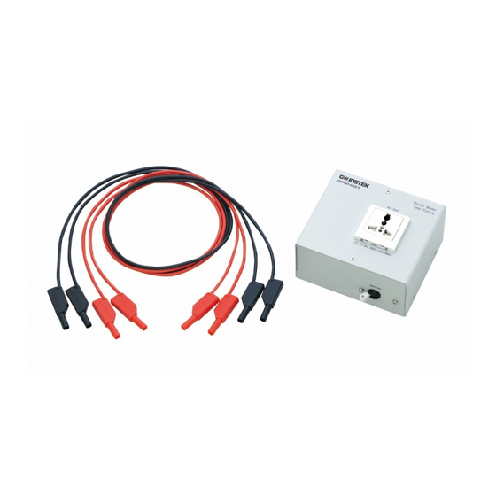
Page 3: Package Contents
NTRODUCTION The GPM-001 power meter test fixture is an accessory designed by GW Instek for applying to the GPM-8213 and GPM-8310. It was designed for customers to handy use the four measurement terminals on the front panel of the GPM-8213 to test products, which eliminates the need for repetitive wiring as well as the trouble caused by wiring. - Page 4 Dimensions...
-
Page 5: Front Panel
Appearance Front Panel Upper Panel Power Switch AC power output AC power output (universal socket) (EU socket) Rear Panel Voltage measurement Current measurement terminals terminals AC power input socket Grounding terminal... - Page 6 Use the GPM-001 power meter test fixture to perform the AC input power consumption test of product. Connect the GPM-001 in series to the DUT and the mains. The wiring method is related to the test accuracy. Two kinds of wiring methods are suggested as below.
- Page 7 CURRENT VOLTAGE AC 10A AC 600V CAT II 300V Connect the voltage measurement terminal to the side When measuring of power supply input. Please use V+1 and V-terminal a smaller current as voltage measurement terminals and I + and I- terminal as current measurement terminals.
- Page 8 1. Insert the input terminal of DUT to the AC Steps universal socket of the GPM-001 power meter test fixture. 2. The voltage terminal and the current terminal will be assigned automatically from the AC socket through the GMP-001 power meter test fixture.
- Page 9 Wiring method of GPM-8310 Connect the voltage measurement terminal to the side When measuring of the load. Please use V+2 and V-terminal as voltage a larger current measurement terminals and I + and I- terminal as current measurement terminals. Connection Power meter Power supply Product under test...
- Page 10 Connection Power meter Power supply Product under test Power loss = (Input current[A]) x 505mΩ CURRENT VOLTAGE EXT1 10V MAX EXT2 2V MAX 20A MAX 600V MAX CAT II 600V...
- Page 11 1. Insert the input terminal of DUT to the AC Steps universal socket of the GPM-001 power meter test fixture. 2. The voltage terminal and the current terminal will be assigned automatically from the AC socket through the GMP-001 power meter test fixture.
Need help?
Do you have a question about the GPM-001 and is the answer not in the manual?
Questions and answers