
Related Manuals for W.E.ST. PQ-132-U


Summary of Contents for W.E.ST. PQ-132-U
- Page 1 Technical Documentation PQ-132-U p/Q-controller, pressure limiting controller for hydraulic axes...
-
Page 2: Table Of Contents
SIGNAL:U (Type and polarity of the output signal) ..................27 Special commands ............................. 28 5.7.1 TS (Sample time) ............................28 5.7.2 AINMODE (Input scaling mode) ......................... 28 5.7.3 AIN (Free analogue input scaling) ......................29 Page 2 of 34 PQ-132-U 05.06.2020... - Page 3 PROCESS DATA (Monitoring)..........................30 Appendix ..................................31 Failure monitoring ............................... 31 Troubleshooting ..............................32 Description of the command structure ........................ 33 Notes ..................................34 Page 3 of 34 PQ-132-U 05.06.2020...
-
Page 4: General Information
1 General Information 1.2 Order number - with programmable analogue output (±10 V differential output or 4… 20 mA) and PQ-132-U analogue sensor interfaces Extended versions - with programmable analogue output (±10 V differential output or 4… 20 mA) and... -
Page 5: Symbols Used
We reserve the right to make technical modifications due to further development of the product described in this manual. The technical information and dimensions are non-binding. No claims may be made based on them. This document is protected by copyright. Page 5 of 34 PQ-132-U 05.06.2020... -
Page 6: Safety Instructions
The module may not be used in an explosive environment. To ensure adequate cooling the ventilation slots must not be covered. The device must be disposed of in accordance with national statutory provisions. Page 6 of 34 PQ-132-U 05.06.2020... -
Page 7: Characteristics
Parameterset linked ramp times/detachable Force- / pressure controller with one sensor Differential pressure control with two pressure sensors Fault diagnosis and extended function checking Simplified parameterization with WPC-300 software Page 7 of 34 PQ-132-U 05.06.2020... -
Page 8: Compatibility
2. Simplified and intuitive parameterization of the analogue inputs and sensors 3. Compatibility mode of the input scaling (AINMODE), if necessary 4. Adaptation of the output signal (current or voltages) and the polarity with the command SIGNAL:U (the POL commando is removed) Page 8 of 34 PQ-132-U 05.06.2020... -
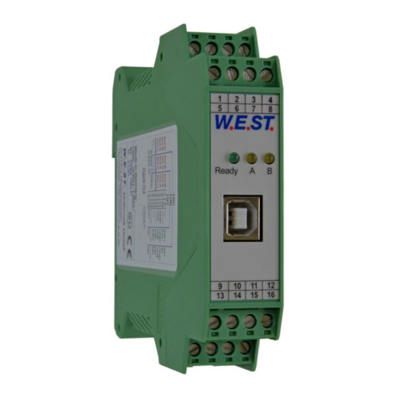
Page 9: Device Description
Made in Germany Date: Add.: W.E.ST. Elektronik D-41372 Niederkrüchten Homepage: http://www.w-e-st.de Typenschild und Anschlussbelegung Type plate and terminal pin assignment Ready Klemmblöcke (steckbar) LEDs Terminals (removable) USB-Interface 9 10 11 12 14 15 16 Page 9 of 34 PQ-132-U 05.06.2020... -
Page 10: Use And Application
Switched inductances (relays and valve coils) which are connected to the same power supply must always be provided with appropriate overvoltage protection directly at the coil. Page 10 of 34 PQ-132-U 05.06.2020... -
Page 11: Typical System Structure
This minimal system consists of the following components: (*1) Proportional valve (or control valve) (*2) Hydraulic cylinder (*3) Pressure/force sensor with analogue interface (*4) control module PQ-132-U… (*5) Interface to PLC with analogue and digital signals Page 11 of 34 PQ-132-U 05.06.2020... -
Page 12: Method Of Operation
To go backwards for keeping the force is possible. The pressure/force is determined via the analogue inputs X1 and X2. For differential pressure control the ac- tual value is calculated (X1 – X2). Page 12 of 34 PQ-132-U 05.06.2020... -
Page 13: Commissioning
With the start signal (RUN), the controller is activated. On the intended pressure point is the Assembly control the pressure according to the setpoint. Optimize controller Now optimize the control parameters according to your application and your re- quirements. Page 13 of 34 PQ-132-U 05.06.2020... -
Page 14: Technical Description
Enable (PIN 8) is deactivated or a failure (current input or intern) has been detected (depending on the SENS command). STATUS output (error monitoring): PIN 2 The axis is within the pre-set monitoring range. OFF: The axis is without the pre-set monitoring range. Page 14 of 34 PQ-132-U 05.06.2020... -
Page 15: Led Definitions
WPC. If the function of the module has changed via the FUNCTION parameter, all parameters are deleted purposely and set to default values. In this case the LEDs indicate no error, but a desired state. To acknowledge please save. Page 15 of 34 PQ-132-U 05.06.2020... -
Page 16: Block Diagram
4.4 Block diagram Page 16 of 34 PQ-132-U 05.06.2020... -
Page 17: Typical Wiring
A : 24 V supply B : 0 V supply C : GND or enable PIN 12 PIN 15 D : + differential input PIN 16 E : - differential input F : diagnostics PE - Page 17 of 34 PQ-132-U 05.06.2020... -
Page 18: Technical Data
-20… 70 [°C] Storage temperature Humidity < 95 (non-condensing) Connections Communication USB type B Plug connectors 4 x 4-pole terminal blocks via the DIN mounting rail EN 61000-6-2: 8/2005 EN 61000-6-4: 6/2007 + A1:2011 Page 18 of 34 PQ-132-U 05.06.2020... -
Page 19: Parameters
Sensor nominal pressure OFFSET:X1 mbar Sensor offset Sensor scaling X2 SIGNAL:X2 U0-10 Type of input N_RANGE:X2 Sensor nominal pressure OFFSET:X2 Mbar Sensor offset Command signal scaling SIGNAL:W U0-10 Type of input SIGNAL:Q U+-10 Type of input Page 19 of 34 PQ-132-U 05.06.2020... - Page 20 0,1 ms Control loop sample time Scaling mode AINMODE EASY Input scaling mode AIN:I i= X1|X2|W|Q Free scaling of the analogue inputs. Gets activated when AINMODE is switched over to MATH. 1000 1000 0,01 % Page 20 of 34 PQ-132-U 05.06.2020...
-
Page 21: Basic Parameters
Auto reset mode. All monitoring functions are active. If the failure doesn’t exist anymore, the mod- AUTO: ule automatically resumes to work. Normally the monitoring functions are always active because otherwise no errors are detectable via the READY output. Deactivating is possible mainly for troubleshooting. Page 21 of 34 PQ-132-U 05.06.2020... -
Page 22: Pin:5 (Function Of Pin 5)
This is necessary if using valves without error detection for signals lower than 4 mA. If the valve has an error detection it goes into a defined position after switching of the output. Page 22 of 34 PQ-132-U 05.06.2020... -
Page 23: Input Signal Adaptation
This parameter is entered in 0,01%. Alternative to the analog input the flow can be specified as a parameter. When the analogue input is switched off with SIGNAL: Q = OFF, the configured value in PRESET: Q gets active. Page 23 of 34 PQ-132-U 05.06.2020... -
Page 24: F_Offset (Feedback Offset)
Command Parameters Unit Group OFFSET:I i= X1|X2 mbar EASY x= -60000…60000 This parameter is entered in bar. Adjustment of zero point of the sensor is realized with it. Xi(result) = Xi(analogue) – „OFFSET:Xi x“ Page 24 of 34 PQ-132-U 05.06.2020... -
Page 25: Ramps And Pid Control Parameters
1… 600000 The ramp times for the pressure command value are defined here in ms. Two separate time values are entered for increasing and decreasing pressure. They take effect on the command signal input (W). Page 25 of 34 PQ-132-U 05.06.2020... -
Page 26: C (Pid Control Parameters)
0.. 10 V skaling 4.. 20 mA x2 actual value 0.. 10 V skaling C:T1 4.. 20 mA pressure controller C(1|2):P P-Gain C(1|2):I I-Gain C(1|2):D D-Gain C(1|2):D_T1 T1 filter or D-Gain C(1|2):I_ACT Activating of the integrator Page 26 of 34 PQ-132-U 05.06.2020... -
Page 27: Output Signal Adaptation
The valve have to be deactivated in case of < 4 mA input signal. Otherwise the EOUT command can be used to get a defined output signal. Page 27 of 34 PQ-132-U 05.06.2020... -
Page 28: Special Commands
Attention: This command does not show up in the parameter list in WPC. It has to be entered manually in the terminal window. After any change of AINMODE, module default data should be applied (by pressing the corresponding button in WPC-300) Page 28 of 34 PQ-132-U 05.06.2020... -
Page 29: Ain (Free Analogue Input Scaling)
Current input: theoretically usable range -20… 20mA (40mA) for a working range of -100… 100% (two solenoids). AIN:I 6000 C OR Really usable are only 4… 20mA (16mA) for both solenoids with AIN:I 2500 1000 6000 C 12mA zero point setting. Page 29 of 34 PQ-132-U 05.06.2020... -
Page 30: Process Data (Monitoring)
Feedback signal 1 (input signal) Feedback signal 2 (input signal) Control deviation Output signal of the controller Output signal The process data are the variables which can be observed continuously on the monitor or on the oscilloscope. Page 30 of 34 PQ-132-U 05.06.2020... -
Page 31: Appendix
EEPROM Data error The output is deactivated. (when switching on) The module can only be acti- vated by saving the parameters again! CAUTION: Take care of the EOUT command. Changes will influence the behavior. Page 31 of 34 PQ-132-U 05.06.2020... -
Page 32: Troubleshooting
Electrical problems could be: the pressure is instable. Electrical noise at the wire of the power supply. Very long sensor cables (> 40 m) and sensor signal interference. Incorrect parameterization of the pressure regulator. Page 32 of 34 PQ-132-U 05.06.2020... -
Page 33: Description Of The Command Structure
Examples: nnnn = “MIN”, i = “A” and x = “2000” MIN:A 2000 nnnn = „OFFSET“ and x = „50“ OFFSET 50 nnnn = “C”, i = “IC” and x = “2000” C:IC 2000 Page 33 of 34 PQ-132-U 05.06.2020... -
Page 34: Notes
7 Notes Page 34 of 34 PQ-132-U 05.06.2020...
Need help?
Do you have a question about the PQ-132-U and is the answer not in the manual?
Questions and answers