Table of Contents
Advertisement
Quick Links
Thank you for choosing a NIVELCO instrument.
We are convinced that you will be satisfied with our product!
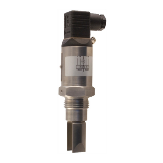
1. APPLICATION
A NIVOSWITCH R–400 type vibration forks are applicable for level switching or flow switching tasks of
normal and explosive liquids. Overfill or dry run protection, as well as pump control, is also possible with the
NIVOSWITCH vibration forks in low/high fail-safe operation mode.
2. TECHNICAL DATA
2.1 G
ENERAL DATA
R–400 / R–400 Ex
40 bar (580 psi),
Medium pressure
PP flange: 6 bar (87 psi)
see "Temperature diagrams"
Insertion length
69...3000 mm (0.225...10 ft)
Material of wetted
DIN 1.4571,
parts
ECTFE / PFA coating
Medium
−40...+130 °C (−40...+266 °F)
temperature
see table in 5.1 and diagrams
−40...+70 °C (−40...+158 °F)
see table in 5.1 and diagrams
Ambient
R–4–L Ex;
temperature
R–4–M and –4–K
−25...+70 °C (−13...+158 °F)
0.7 kg/dm
Medium-density
Medium viscosity
10000 mm
2
/s (cSt)
When
0.5 sec
immersed
Response
time
When free: 1 s
When free
see response time diagram
Output mode
Bi-color (LED)
indication
Output can be changed
by test magnet
2.3 W
AC
3-
DC
IRE
AND
WIRE
VERSIONS
T
YPE
Electrical connection (wire cross section)
Mechanical protection
High/low mode setting
(Low fail-safe – "L", High fail-safe – "H")
Output
Output protection
Supply voltage
Consumption
Voltage drop (in switched-on state)
Electrical protection
max. continuous
Current load
min. continuous
max. impulse
Residual current (in switched off state)
2.4 A
CCESSORIES
- User's manual
- EU- declaration of conformity
- Warranty Card
- 1× RPS–101 type test magnetic-screwdriver (optional)
2.5 O
C
RDER
ODES
T
YPE
Tube + plastic
(ECTFE / PFA) coated fork
Tube + fork: 1.4571
Tube + highly polished fork
Tube + fork: 1.457, without reed sensor
(1)
(1)
Ex version not available
2.2 T
-
DC,
WO
WIRE
E
NORMAL AND
X APPROVED VERSION
R–4–6
TYPE
R–4–8Ex
Electrical connection
Ingress Protection
IP65
Output
Consumption
Power supply (U)
Setting operation
mode
3
Electrical protection
Ex marking
(RC–4–Ex,
RG–4–Ex)
Ex marking
(RB–4–Ex)
Intrinsically safe data
Reference document
number
2-
WIRE
R–4–1
Connector
(max cable length 30 m [100 feet])
IP65
Connection within connector
2-wire AC, for serial connection
—
20...255 V AC, 50/60 Hz
Depending on load
< 10.5 V
Class I
350 mA AC 13
10 mA / 255 V, 25 mA / 24 V
1.5 A / 40 ms
< 6 mA
NIVOSWITCH
C
P
ODE
ROCESS CONNECTION
1" BSP
B
1½" BSP
C
1" NPT
G
1½" NPT
E
DN50 PN16 PP DIN
DN50 PN40 1.4571 DIN
ANSI 2" RF150 PP
ANSI 2" RF600 1.4571
JIS 10K 50A PP
JIS 40K 50A 1.4571
TriClamp 1½"
TriClamp 2"
DN40 Pipe coupling
DN50 Pipe coupling
R–4–K
R–4–7
R–4–L Ex
R–4–9Ex
3 m (10 ft) cable
Connector
(2 x 0.5 mm
[AWG20])
IP67
IP68
DC current change:
When free: 9 ±1 mA;
When immersed: 14 ±1 mA
< 0.5 W
15...29 V DC
Provided by the PKK–312–8Ex
remote switching unit for the Ex-version
By switch on the remote switching unit
(Low fail-safe – "L", High fail-safe – "H")
Class III.
II 1G Ex ia IIC T6...T4 Ga
II 1G Ex ia IIB T6...T4 Ga
U
= 29 V; I
= 100 mA; P
= 1.4 W;
i
i
i
C
= 7 nF; L
= 0 mH
i
i
For temperature classes see 5.1.
rcm4004m0600h_10
AC
R–4–2
R–4–3
3 m (10 feet) integral cable,
4 x 0.75 mm
(AWG18)
2
IP68
Wire selectable
Switch selectable
- 1× Sealing ring (2 mm [0.079"] thick Klinger Oilit)
- Sliding sleeve for adjustable types: RPH–112 (optional)
R
– 4
C
P
ODE
ROBE LENGTH
M
Short (69 mm [2.7"])
H
Standard (125 mm [4.9"])
P
0.2...3 m (0.66...10 feet)
02...30
N
F
G
A
B
J
K
T
R
D
E
Note: Flanged versions have 1" process connection
2
3-
DC
WIRE
R–4–M
Connector
IP65
IP67
Connection within
connector
Field selectable,
PNP/NPN transistor switch
Reverse polarity, overcurrent and short-circuit protection
12...55 V DC
< 0.6 W
< 4.5 V
Class III
I
= 350 mA DC / U
= 55 V DC
max
max
–
–
< 100
A
–
*
C
O
/ C
ODE
UTPUT
ERTIFICATES
00
2-wire AC + connector
01
2-wire AC + cable
3-wire DC + connector
3-wire DC + cable
2-wire DC + connector
2-wire DC + cable
2-wire DC + connector + Ex
2-wire DC + cable + Ex
2-wire DC + M12 connector
2-wire DC + M12 connector + Ex
3-wire DC + M12 connector
* Ex version with Ex mark
R–4–4
3 m (10 feet) integral cable,
5 x 0.5 mm
(AWG20)
2
(max. cable length 30 m [100 feet])
IP68
Wire selectable
Field selectable, galvanically
isolated PNP/NPN transistor switch
C
ODE
1
2
3
4
6
7
8
9
K
L
M
rcm400en2111h 1/4
Advertisement
Table of Contents

Related Manuals for NIVELCO NIVOSWITCH R-400


Summary of Contents for NIVELCO NIVOSWITCH R-400
- Page 1 Thank you for choosing a NIVELCO instrument. We are convinced that you will be satisfied with our product! 1. APPLICATION A NIVOSWITCH R–400 type vibration forks are applicable for level switching or flow switching tasks of normal and explosive liquids. Overfill or dry run protection, as well as pump control, is also possible with the NIVOSWITCH vibration forks in low/high fail-safe operation mode.
- Page 2 2.6 T EMPERATURE DIAGRAMS Version with sliding sleeve Version with flange Pressure [p ] as a function of temperature [T ] for all versions (except PP flanged version) T [°C] I 350 mA TriClamp (ISO 2852) Pipe coupling 100 mA 1 mA 95 105 T [°C]...
- Page 3 4.1.2. Version with cable R–4–2 This version is with 4-wire cable equipped. Only one of the black and brown wires is used, dependent on the operating mode (High or Low). Provide also a terminal block connection for the unused wire. Low viscosity liquids On applications, where the fork- tines are easily freed from the...
- Page 4 Output decontaminated. Our official form (Returned Equipment Handling Form) must be enclosed. Download it from our website www.nivelco.com. The device must be Immersed 14 1 mA sent with a declaration of decontamination. Please provide a statement in the declaration that the decontamination process is completed, the device is clean and free from harmful materials, and there are no hazardous substances on it.
Need help?
Do you have a question about the NIVOSWITCH R-400 and is the answer not in the manual?
Questions and answers