Advertisement
Quick Links
Thank you for choosing a NIVELCO instrument.
We are convinced that you will be satisfied with our product!
1. INTRODUCTION
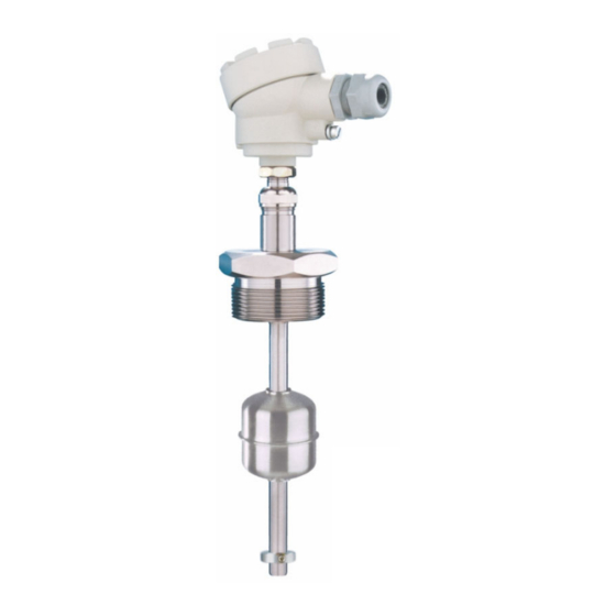
The interaction of the magnetic float and the reed relays (incorporated in the protection tube) is the basis of the
NIVOPOINT magnetic float level switch series operation. They are suitable for level indication of normal and
explosive liquids and can be used for level control tasks. The protecting tube contains a max. of 5 relays. Parts
of the instrument are a probe tube with magnetic float and a housing containing the connection terminal.
The magnetic float moves alongside the protection tube tracking the level of the liquid and activating the reed
relays. As the float passes a relay it changes the output state of the relay which retains this state latching until
the level decreases and the float moves again along the respective relay to switch its state back.
2. TECHNICAL DATA
2.1. G
ENERAL DATA
TYPE
MR-
Insertion length
Stainless steel
Material of probe rod
(DIN 1.4571 / BS 316Ti)
Material of float
53.5 × 60 mm
Float sizes (standard
included)*
(2.1" × 2.36")
2.5 MPa (25 bar)
[363 psig]
Max. process pressure
at +20 C (68 F)
Medium-density
min. 0.8 kg/dm
(Specific gravity)
–40...+150 °C
Medium temperature
(–40...+302 °F)
Ambient temperature
Output
Switching rate
Switching differential
Distance between reed-
switches
Electrical connection
1", 1½", 2" BSP
Process connection
1", 1½", 2" NPT
1", 1½", 2½", 3", 4" TriClamp
Sealing material
Klingerit for BSP
Electrical protection
Ingress protection
Dimension of the housing
Mass
0.4 kg + 0.3 kg/m (0.88 lb + 0.2 lb/ft)
* For details of non-standard floats, see 2.6. Float selection
** Note: the device must be installed with Ex d IIC certified explosion-proof cable gland.
2.2. E
,
XPLOSION PROTECTION
EX MARKINGS
2.2.1 ATEX C
N
.: E
NB 17 ATEX 0003 X/1
ERTIFICATE
O
X
T
YPE
MR--7Ex
Ex marking (ATEX)
Reference document
number
MP-
0.25...3 m (0.85...10 ft)
Material of wetted parts
PFA / PP coated
1.4404
PVDF, PP
76 × 87 mm
(3" × 3.42")
0.6 MPa (6 bar)
[88 psig]
at +20 C (68 F)
min. 0.7 kg/dm
3
3
–40...+80 °C
(–40...+176 °F)
–40...+95 °C
(–40...+203 °F)
1...5 × reed-switches, connecting one side of each, NO/NC
120 W / VA, 250 V AC/DC, 3 A /reed relay, summary max. 9 A
<10 mm (0.4")
min. 110 mm (4.35")
M20x1.5 6...12 for cables
(0.25...0.5")
terminal, wire cross section: 0.5...2.5 mm
PP flange
DN80, DN100
—
Class I, Protecting cable 4 mm
IP67 (as per MSZ EN 60529:2015)
116 × 80 × 65 mm
(4.56 × 3.15 × 2.56")
,
EX LIMIT DATA
With cable gland
Without cable gland
MR--8Ex
II 1/2 G Ex db IIC T6...T3 Ga/Gb
mra1053m0600h_12
MR--7Ex
MR--8Ex
Stainless steel
(DIN 1.4571 / BS 316Ti)
1.4404
53.5 × 60 mm
(2.1" × 2.36")
2.5 MPa (25 bar)
[363 psig]
at +20 C (68 F)
min. 0.8 kg/dm
3
See: Temperature limit data for Ex
approved models table
M20x1.5
7...12 for
without cable gland
**
cables
(0.28...0.47")
(AWG20...AWG14)
2
1", 1½", 2" BSP
1", 1½", 2" NPT
1", 1½", 2½", 3", 4" TriClamp
Klingerit for BSP
(AWG25)
2
124 × 80 × 65 mm
(4.9 × 3.15 × 2.56")
0.45 kg + 0.3 kg/m (1 lb + 0.2 lb/ft)
2.2.2 T
EMPERATURE LIMIT DATA FOR
Class
Max. ambient temperature
from –40 °C (–40 °F)
Max. medium temperature
from –40 °C (–40 °F)
2.3. A
CCESSORIES
User's Manual,
Warrant Card,
EU declaration of Conformity,
1 × Gasket (for threaded versions)
E
X APPROVED MODELS
T6
T5
T4
+80 °C
+95 °C
+95 °C
(176 °F)
(203 °F)
(203 °F)
+80 °C
+95 °C
+130 °C
(266 °F)
(176 °F)
(203 °F)
3/1
mra105en2112h
T3
+95 °C
(203 °F)
+150 °C
(302 °F)
Advertisement

Related Manuals for NIVELCO NIVOPOINT


Summary of Contents for NIVELCO NIVOPOINT
- Page 1 The interaction of the magnetic float and the reed relays (incorporated in the protection tube) is the basis of the NIVOPOINT magnetic float level switch series operation. They are suitable for level indication of normal and explosive liquids and can be used for level control tasks. The protecting tube contains a max. of 5 relays. Parts of the instrument are a probe tube with magnetic float and a housing containing the connection terminal.
- Page 2 2.4. O RDER CODE OT ALL COMBINATIONS POSSIBLE NIVOPOINT – – WITCHING ROBE ROBE ROCESS CONNECTION ERTIFICATE POINTS LENGTH LENGTH 1" BSP 1 × NO/NC Standard 2" BSP 2 × NO/NC 0.1 m 1" NPT 3 × NO/NC Ex without cable gland 2"...
- Page 3 The unit should be mounted in vertical position via its process connection and protection! handled with care to avoid any damage or bend of the protection tube during The plastic protective cap should be removed before installing NIVOPOINT transportation or installation! MR☐☐☐☐8Ex, and the device must be equipped with a properly assembled and sealed and cable gland with “Ex d”...
Need help?
Do you have a question about the NIVOPOINT and is the answer not in the manual?
Questions and answers