Table of Contents
Advertisement
Quick Links
Thank you for choosing a NIVELCO instrument.
We are convinced that you will be satisfied with our product!
1. INTRODUCTION
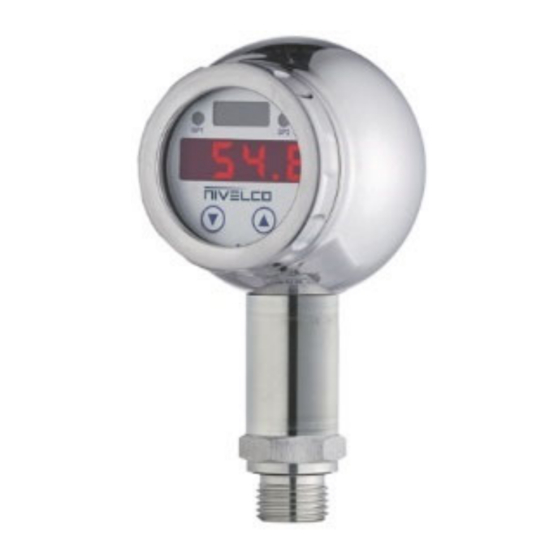
The NIPRESS DK−500, DK−600, and DK−700 pressure switches with flush sensor are a successful combination of an
intelligent pressure switch and a 4-digit LED display. This makes it suitable for numerous applications in various industrial
sectors for monitoring and controlling the pressure via switching outputs. It comes with a rotatable display and with PNP contact
outputs. Ex version is also available.
DK-500 series is an electronic pressure switch with Stainless Steel sensor. Excellent for applications in the area of plant and
machine engineering, heating and air conditioning, and environmental engineering (water – sewage – recycling).
DK-600 series is an electronic pressure switch with ceramic sensor. It is suitable for the usage in viscous, pasty or highly
contaminated media. The robust rotatable Stainless-Steel housing is designed for using under rough conditions and in hard
operating environment.
DK-700 series is an electronic pressure switch with welded Stainless-Steel sensor. This pressure switch has been developed
for process industry, especially for food industry and pharmacy.
2. TECHNICAL DATA
G
ENERAL DATA
Type
DK-5-
Measuring range
(−14.5...0; 0...8700 psig) Per order code
Overload tolerance
p ≥ 0.4 bar (5.8 psig): 0.25%;
Accuracy
0.5%
Medium temperature
−40°C...+125°C (−40°F...+257°F)
Ambient temperature
Sensor
Stainless steel 1.4435 (316L)
FKM; option: welded version
Seal
without seal (max. 40 bar
[580 psig])
Process
Stainless steel 1.4404 (316L)
connection
Housing
Stainless steel 1.4404 (316L)
Output
Switching output
Short-circuit resistant PNP output (max.: 125 mA), delay time adjustable between 0...100 s
Power supply (U
)
(1)
Supply
Load resistance of
analog output
4-digit (7 mm [0.28 inch]), red LED display;
Display
Process connection
Electrical connection
Ingress protection
Electrical protection
Weight
(1)
For information of Ex certified devices, see Special data for Ex certified models chart.
S
E
PECIAL DATA FOR
X CERTIFIED MODELS
Type
Ex marking
Ex power supply
Intrinsically safety data
Max. switching current
(2)
Permissible temperatures for environment
(2)
The real switching current depends on the power supply unit
2.2 ORDER CODES
2.1 DK-500 ORDER CODE (N
OT ALL COMBINATIONS POSSIBLE
M
EASURING
P
C
ROCESS CONNECTION
ODE
METHOD
Switch
K
¼" BSP
½" BSP
¼" NPT
½" NPT
dkc5127a0600p_01 - 1/5
DK-62-
−1...0; 0...600 bar
Per order code
0.5%
−40°C...+85°C (−40°F...+185°F)
CeramicAl
O
96%
2
3
FKM
(option: EPDM, max. 160
bar [2320 psig]), NBR
Stainless steel 1.4404 (316L)
(option: PVDF only with ½"
BSP, max. 60 bar [870 psig])
Stainless steel 1.4301 (304)
1 or 2 independent PNP contacts, (optional analog output: 4...20 mA / 0–10 V)
Without analog output: 13–36 V DC;
3-wire current output: 24 V DC ±10%;
3-wire voltage output: 24 V DC ±10%
2- wire current output: R
=[(U
max
Supply
3- wire current output: R
= 500 Ω;
max
Accuracy: 0.1% ±1 digit;
Damping: 0.3–30 sec (adjustable)
Per order code
M12x1 (5-pin, metal)
IP67
Class III (SELV)
~0.4 kg (~0.88 lb)
(
4...20 mA / 2-
ONLY FOR
DK-5-
!)
NIPRESS D
K
R
/
(1)
ANGE
C
ODE
O
[bar]
VERPRESSURE
A
-1 – 0 / 5
C
0 – 0.1 / 0.5
G
0 – 0.16 / 1
H
0 – 0.25 / 1
0 – 0.4 / 2
0 – 0.6 / 5
0 – 1 / 5
0 – 1.6 / 10
0 – 2.5 / 10
0 – 4 / 20
0 – 6 / 40
0 – 10 / 40
0 – 16 / 80
0 – 25 / 80
0 – 40 / 105
0 – 60 / 210
0 – 100 / 210
0 – 160 / 600
0 – 250 / 1000
0 – 400 / 1000
0 – 600 / 1000
DK-7-/DL-7-
−1...0; 0...40 bar
(−14.5...0; 0...580 psig) Per order code
p ≥ 0,4 bar (5.8 psig):
0.25%; 0.5%
−40°C...+125°C (−40°F...+257°F) silicone oil
−10°C...+125°C (+14°F...+257°F) food grade oil
Stainless Steel 1.4435 (316L)
FKM < 200°C (392 °F),
FFKM > 200°C (392 °F)
Stainless steel 1.4435 (316 L)
(max. 60 bar [870 psig])
Stainless steel 1.4404 (316L);
2-wire current output: 13–36 V DC
-U
)/ 0.02 A], [Ω]
Supply min.
3- wire voltage output: R
= 10 kΩ
min
Range of indication: −1999...+9999;
~0.5 kg (~1.1 lb)
)
WIRE
DK-62-
Use only with Ex ia certified power supply module!
U
= 28 V DC, I
= 93 mA, P
imax
imax
−25°C...+70°C (−13°F...+158°F)
– 5
–
*
A
C
CCURACY
ODE
0
0.25 %
(2)
1
0.5 %
R
2
3
4
5
6
7
8
9
A
B
C
D
E
F
* Ex versions are marked "Ex" right after the type designation on the label
G
(1)
Custom measuring range available; subject to prior negotiation.
H
(2)
p ≥ 0,4
J
(3)
Ex versions are available on special request. .
K
2.1 A
CCESSORIES
User's and programming manual
Warranty card
EU declaration of conformity
DK-7- / DL-7-
(Pending)
15–28 V DC
= 660 mW, C
≈ 0 nF, L
≈ 0 mH
imax
i
i
70 mA
O
/ C
C
UTPUT
ERTIFICATES
ODE
1
1 PNP switching output
2
2 PNP switching output
4...20 mA 2-wire + 1 PNP
switching output / Ex ia G
(3)
C
ODE
7
9
F
Advertisement
Table of Contents

Related Manuals for NIVELCO NIPRESS DK-500


Summary of Contents for NIVELCO NIPRESS DK-500
- Page 1 Thank you for choosing a NIVELCO instrument. We are convinced that you will be satisfied with our product! 1. INTRODUCTION The NIPRESS DK−500, DK−600, and DK−700 pressure switches with flush sensor are a successful combination of an intelligent pressure switch and a 4-digit LED display. This makes it suitable for numerous applications in various industrial sectors for monitoring and controlling the pressure via switching outputs.
- Page 2 2.2 DK-600 ORDER CODE (N OT ALL COMBINATIONS POSSIBLE – 6 2 – NIPRESS EASURING ANGE ROCESS CONNECTION CCURACY UTPUT ERTIFICATES [bar] METHOD VERPRESSURE Switch ¼” BSP -1 – 0 / 4 0.5 % 1 PNP switching output ½” BSP 0 –...
- Page 3 3.3 SPECIAL CONDITIONS OF SAFE USE 5. WIRING Use a shielded and twisted multicore cable for the electrical connection. Make sure the installation is complete with no visible defects before turning on the For devices with cable gland, make sure that the external diameter of the cable used is within device.
- Page 4 6.3 CONFIGURING THE ANALOG OUTPUT (EXAMPLE) WIRE SYSTEM (FOR 4…20 MA / 3-WIRE ADJUSTABLE) The analog output can be configured in the menus ZP (zero point) and EP (end point). The following example shows how to use them: In this example, the device has a measurement range of 0–400 bar (0–5800 psi). The output analog signal: 0 bar (0 psi) = 4.00 mA 200 bar (2900 psi) = 12.00 mA...
- Page 5 Load configuration stored on the device (Menu 32). (Choose from 1 to 5). (Returned Equipment Handling Form) must be enclosed. Download it from our website www.nivelco.com. The device must be sent with a declaration of decontamination. Please Menu 27 – Store configuration provide a statement in the declaration that the decontamination process is completed, the (only 4…20 mA / 3-wire adjustable)
Need help?
Do you have a question about the NIPRESS DK-500 and is the answer not in the manual?
Questions and answers