Advertisement
Quick Links
Thank you for choosing a NIVELCO instrument.
We are convinced that you will be satisfied with our product!
1. APPLICATION
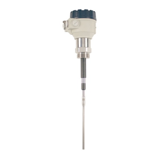
The NIVOCAP CK capacitive level switches operate in the RF (radio-frequency) ~ 130 kHz range.
The instrument is less sensitive to material adhesions caused by the measuring probe's design and the so-called reference
probe-based operating principle. The device is capable of level switching in solids and powders with a dielectric constant
greater than 1.5 relative permittivity (Ɛr) and to a limited extent in liquids (see 2.1 General data).
The device needs to be calibrated after it is installed.
During operation, the device evaluates the capacitance difference of the connected probe continuously. Until the probe is
in the air (the medium does not reach the probe) the measuring and reference probe is at the minimal capacitance value
(ε
=1) relative to the instrument housing. When the medium reaches the probe, the capacitance will increase
relative
(ε
≥1). The device measures the capacitance change relative to the reference value stored during the calibration
relative
procedure.
The reference probe is designed so that the material deposits on the probe are ignored, preventing any false switching.
There are four measuring ranges switchable on the device (see Chapter 4: Sensitivity Ranges)
4
sensitivity range:
0.5 pF, ε
th
relative
3
sensitivity range:
2.5 pF, ε
rd
relative
2
sensitivity range:
8.0 pF, ε
nd
relative
1
sensitivity range:
18 pF,
ε
st
relative
2. TECHNICAL DATA
2.1 G
ENERAL DATA
Type
CK(D,G,M,P,H,N)–1–1
CM(D,G,M,P,H,N)–1–1
Probe length
Material of wetted parts
Process connection
Ambient temperature
(1)
Medium temperature
(1)
(for solids)
Medium temperature for
high-temperature version
(1)
(for solids)
Medium temperature
(1)
(for liquids)
Max. process pressure
Response time (selectable)
Power supply (universal)
Power consumption
Housing material
Electrical connection
(1)
Electrical protection
Ingress protection
Weight
(1)
For explosion-proof design, see section 2.3 Ex information
2.3 E
X INFORMATION
ATEX
Ex marking
IEC Ex
Electrical connection
Thermal Properties
Medium temperature min.: –30 °C (−22 °F);
max.:
Ambient temperature min.: –30 °C (−22 °F);
max.:
Highest permissible surface temperature
of the process connection
Temperature classes
2.4 O
UTPUT DATA
Output type
Output rating
Output protection
= 1.5...2.0
= 2.0...4.0
= 4.0...7.0
= > 7.0
Standard
With Extension Rod
CK(R,L,E,F,V,Z)–1–1,
CM(R,L,E,F,V,Z)–1–1
0.3...0.6 m (1.3...2 ft)
0.7...3 m (2.3...10 ft)
1.4571 (316Ti) stainless steel + PPS insulation
As per order code (see 2.5 Order Codes)
–30...+65 °C (–22...+149 °F)
–30...+110 °C (−22...+230 °F)
–30...+235 °C (−22...+455 °F)
0...+65 °C (+32...+149 °F)
16 bar (1.6 MPa, 232 psi)
0.15...15 sec
20...250 V AC (50/60 Hz) or 20...50 V DC
2.5 VA / 2 W
Powder-coated aluminum
2× M20x1.5 plastic cable glands, for cable Ø6...Ø12 mm (.236"... .472"),
2× terminal blocks for 0.5...1.5 mm² (AWG20...15) wire cross section
Class I.
IP67
2 kg + 1.4 kg/m
2 kg (4.4 lb)
(4.4 lb + 1 lb/ft)
2× M20×1.5 metal cable glands for Ø8...Ø13 mm (Ø.315... Ø.5") cable
With extension cable
CKK–1–5, 7Ex
CKC–1–5, 7Ex
+60 °C
+70 °C
(+140 °F)
(+158 °F)
+65 °C
+60 °C
(+149 °F)
(+140 °F)
+80 °C
(+176 °F)
T85°C
T85°C
C–1–1, C–1–5Ex
SPDT (potential-free)
250 V AC, 8 A, AC 1
With Extension Cable
CKK–1–1
CKC–1–1
1...10 m (3.3...33 ft)
1.4571 (316Ti)
+ PPS Insulation;
Cable: PE-coating
–25...+80 °C
(−13...+176 °F)
–
2 kg + 0.6 kg/m
(4.4 lb + 0.4 lb/ft)
C–1–5E
, C–1–7E
X
II 1/2D Ex ta/tb IIIC T85°C...T220°C Da/Db
Ex ta IIIC T85°C...T220°C Da/Db
CK(D,G,M,P,H,N)–1–5, 7Ex
CK(R,L,E,F,V,Z)–1–5, 7Ex
+80 °C
+60 °C
+70 °C
(+176 °F)
(+140 °F)
(+158 °F)
+65 °C (+149
+60 °C
°F)
(+140 °F)
+90 °C
+80 °C
(+194 °F)
(+176 °F)
T95°C
T85°C
T85°C
Relay
—
2.2
ACCESSORIES
User's manual,
Warranty Card,
EU Declaration of Conformity,
2× 3-pole terminal blocks,
1 ½ " klingerit sealing, for BSP only
2× M20x1.5 cable glands
X
Standard, or with extension rod
High-temperature version
CM(D,G,M,P,H,N)–1–5, 7Ex
CM(R,L,E,F,V,Z)–1–5, 7Ex
+95 °C
+110 °C
(+203 °F)
(+230 °F)
+60 °C
+50 °C
(+140 °F)
(+140 °F)
+90 °C
+95 °C
(+194 °F)
(+203 °F)
T95°C
T110°C
Solid-state output
C–1–3, C–1–7Ex
SPST (electronic)
250 V AC, 50 V DC, 1 A
—
Reference document
ckm1051m060bh_06
ckm1051a0600h_02
-
+220 °C (+428 °F)
+35 °C (+95 °F)
+195 °C (+383 °F)
T220°C
ckm105en2106h 1/3
Advertisement

Related Manuals for NIVELCO Nivocap CK


Summary of Contents for NIVELCO Nivocap CK
- Page 1 We are convinced that you will be satisfied with our product! 1. APPLICATION The NIVOCAP CK capacitive level switches operate in the RF (radio-frequency) ~ 130 kHz range. The instrument is less sensitive to material adhesions caused by the measuring probe's design and the so-called reference probe-based operating principle.
- Page 2 2.5 O RDER CODES NOT ALL COMBINATIONS ARE POSSIBLE N I V O C A P C [m (ft)] ERSION ROBE OUSING ROBE ENGTH UTPUT Standard Standard ¾" BSP Aluminum SPDT, potential-free relay High-temp . Standard ¾" NPT 0 (0) 0 (0) SPST, solid-state output Standard / 1"...
- Page 3 (Returned Equipment Handling Form) must be filled and enclosed. Download it from our website www.nivelco.com. The device must be sent back with a declaration of Press and hold the CAL button for a few seconds. decontamination. A statement must be provided in the declaration that the...
Need help?
Do you have a question about the Nivocap CK and is the answer not in the manual?
Questions and answers