Advertisement
980033840-002-1850QS_072722.pdf
1
7/27/22
8:29 AM
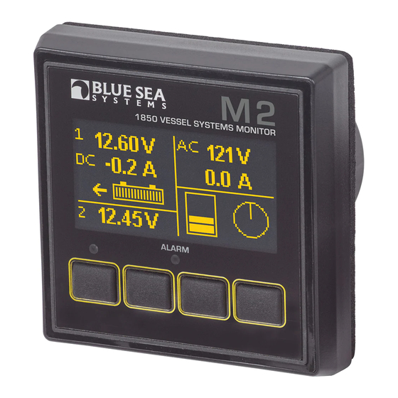
M2 OLED
Digital Monitor
QuickStart Installation Guide
1850 Vessel Systems Monitor
Components Included
M2 Head Unit
Surface Mount Bezel
Surface Mount Gasket
and Seal
Surface Mount Cover
Flat Mount Bezel
Flat Mount Clamp
PN 8255 Shunt
Mounting Ring
Mounting Nut
(1X)
Connectors
Screwdriver
AC Current Transformer
(retail package only)
8256 (1X)
360 Panel Mounting Kit
1525
(sold separately)
Header
#6-32 x 1/4"
Flat Head
Machine Screws
(4X)
Bezel
Panel
Mount
Frame
#6-32 x 3/8"
Carrier
Flat Head
Mount
Machine Screws
(4X)
Footer
bluesea.com/products/1850
Connector Pin Assignment
USB
Micro - USB
M5
NMEA 2000
A. 2 Pin Connector* 3.5mm
Function
Battery 1-
1
2
Battery 1+
B. 2 Pin Connector** 5mm
1
AC Voltage - Neutral
2
AC Voltage - Hot
C. 8 Pin Connector* 3.5mm
1 Required Connection
DC Negative
2 Required Connection
DC Supply / Battery 2+
3
Tank / Bilge 1
Tank / Bilge 2
4
DC Shunt 1–
5
DC Shunt 1+
6
AC Current Transformer – ***
7
AC Current Transformer + ***
8
* Supports wire sizes from 16 to 26 AWG
** Supports wire sizes from 12 to 24 AWG
*** Caution - Incorrect connections may damage the monitor
OPTIONAL
OPTIONAL SECOND TANK
USB
SWITCH
- WORKS BEST IF BOTH
1 2 3 4 5 6 7 8
SPDT
TANKS ARE THE SAME
ON-OFF-ON
SIZE AND SHAPE
PIN 3 OR 4
PINK WIRE
8283
BLACK WIRE
Resistive 2 Wire Sender
USB
1 2 3 4 5 6 7 8
PIN 3 OR 4
5A Fuse
PINK WIRE
PURPLE WIRE
BLACK WIRE
Ultrasonic 3 Wire Senders 1810 and 1811
USB
PIN 3 OR 4
Float Switch Connections
System Overview
5A Fuse
Shunt
Battery 1
From Supply
To loads
AC NEUTRAL
AC HOT
5A Fuse
A
B
1 2
1
2
C
USB
1
2
3
4
5
6
7
8
BusBar
M5
5A Fuse
Bilge
NMEA
2 Bilges or
2000
2 Tanks or
OR
1 Bilge &
Battery 2
1 Tank
Tank
NOTE: To set alarms and for more detailed information,
see the online manual at bluesea.com/products/1850
WARNING
If you are not knowledgeable about electrical systems, have an
electrical professional install this unit. The diagrams in these
instructions pertain to the installation of the unit and not to the overall
wiring of the vessel.
Verify that all AC sources are disconnected before connecting or
disconnecting the Current Transformer (CT). Failure to do so will
generate lethal voltages on the CT.
If an inverter is installed on the vessel, its power leads must be
disconnected at the battery before the unit is installed. Many inverters
have a "sleep mode" in which their voltage potential may not be
detectable with measuring equipment.
If an AC generator is installed on the vessel, it must be stopped and
rendered inoperable before the unit is installed.
Verify that no other DC or AC sources are connected to the vessel's
wiring before installing the unit.
If the unit must be removed, connect the CT leads together before
restoring power to the AC system.
CAUTION
The back of the unit is not waterproof. Do not install where the
back of the monitor is exposed to water.
Installation Steps
1. Choose meter mounting style and location
2. Turn of all power, both AC and DC.
3. Prepare mounting hole using cutout templates
4. Using wiring diagram:
• Install provided 500A/50mV Shunt for DC
current and SoC monitoring
• Install provided 150A/50mA Current
Transformer for AC current monitoring.
• Make all connections to the meter's connector.
Do not put fuses into fuse holders at this time.
5. Plug wired terminal block into the meter
6. Insert fuses into fuse holders, making the fuse to
Pin C2 (DC Supply/Battery 2+) Last.
7. Turn on Power.
Basic Meter Setup
1. Ensure Battery 1 (House Battery) is fully charged
2. Have Battery 1 information ready
a. Battery Bank Nominal Voltage
b. Battery Type
c. Battery Capacity
3. Navigate to DC 1 Setup by going Menu>Setup>
DC1 Setup.
4. Enter information for Battery 1 from step 2
5. Select Set SoC to Full. This reset the meter SoC
to 99%.
6. AC Monitoring requires no setup if using the
included 150A/50mA CT.
7. For instructions on setting Alarms, calibrating
tank senders, or setting up Bilge monitoring see
the full instructions found on our website.
bluesea.com/products/1850
Click here for more information at
bluesea.com/products/1850
bluesea.com
980033840 Rev.002
Advertisement
Table of Contents

Related Manuals for Blue Sea Systems 1850


Summary of Contents for Blue Sea Systems 1850
- Page 1 4. Enter information for Battery 1 from step 2 Tank NOTE: To set alarms and for more detailed information, 5. Select Set SoC to Full. This reset the meter SoC see the online manual at bluesea.com/products/1850 to 99%. WARNING PN 8255 Shunt...
- Page 2 Costs associated with labor or shipping of the Cover Unit Gasket Substrate defective parts are not covered. Blue Sea Systems cannot accept liability for damage NOTE: During Surface Mount due to the misuse of the M2 Meter. installation use cover to align the Bezel 3.40"...
Need help?
Do you have a question about the 1850 and is the answer not in the manual?
Questions and answers