Advertisement
Quick Links
980023490-002-1841QS-1-072722.pdf
1
7/27/22
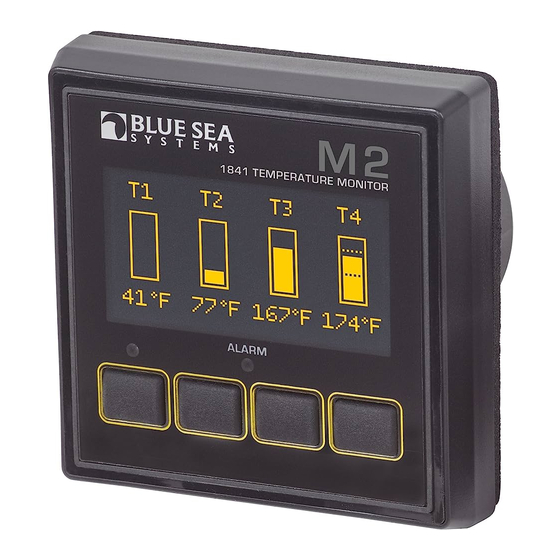
M2 OLED
Digital Monitor
QuickStart Installation Guide
1841 Temperature Monitor
Components Included
M2 Head Unit
Surface Mount Bezel
Surface Mount Gasket
and Seal
Surface Mount Cover
Flat Mount Bezel
Flat Mount Clamp
Mounting Ring
Mounting Nut
2 x 1820
Temperature Sensors
Connector
Screwdriver
2 x 1821
(retail package only)
Temperature Sensors
360 Panel Mounting Kit
separately
PN 1525 sold
Header
#6-32 x 1/4"
Flat Head
Machine Screws
(4X)
Bezel
Panel
Mount
Frame
#6-32 x 3/8"
Carrier
Flat Head
Mount
Machine Screws
(4X)
Footer
bluesea.com/products/1841
10:00 AM
Connector Pin Assignment
Connector Pin Assignment Table
USB
Micro USB Port
8 Pin Connector*
Function
1 Required Connection
DC Negative
2 Required Connection
DC Supply
3
Relay DC Output
4
Relay DC Supply
5
Temperature 1
6
Temperature 2
7
Temperature 3
8
Temperature 4
*The 8 pin low voltage connector supports wire sizes from 16-26 AWG
M2 Meter Navigation
Screen Menu Functions
Press any button to bring up the menu.
1. After start-up, press any button to access the menu.
2. Press the UP or DOWN arrow buttons to scroll
through menu windows.
3. To set alarms and for more detailed information, see
the online manual at bluesea.com/products/1841
System Overview
1841 Temperature Monitor Connections
Temp 1
Temp 2
Temp 3
Temp 4
1 2 3 4 5 6 7 8
5A Fuse
Battery
Relay
OR
Alarm (1070)
OR
LED
(7713 12V)
(8033 Amber)
(7717 24V)
(8171 Red)
(8172 Green)
For the online manual that includes other configurations,
bluesea.com/products/1841
go to
Note: The negative feed of all of the temperature sensors
should terminate as close as possible to pin 1. Use Blue Sea
Systems' PN 2304 Mini Bus with a short 18 AWG guage wire
from pin 1 to the Mini Bus.
Temperature Sensor Connections 1821
1 2 3 4 5 6 7 8
1821 Temperature Sensor
Installation Steps
1. Choose meter mounting style and location.
2. Prepare mounting hole using cutout templates
3. Using wiring diagram and pinout chart make all
connections to the meter Connector. Do not put
fuses into fuse holders at this time.
4. Plug wired terminal block into the meter.
5. Insert 5A fuse into DC Supply wire to power meter.
Basic Meter Setup
1. No setup is required for basic operation.
2. For information regarding advanced setup
options, see the full instructions on our website.
bluesea.com/products/1841
Click here for more information at
bluesea.com/products/1841
bluesea.com
980023490 Rev.002
Advertisement

Related Manuals for Blue Sea Systems 1841


Summary of Contents for Blue Sea Systems 1841
- Page 1 2. Press the UP or DOWN arrow buttons to scroll through menu windows. 3. To set alarms and for more detailed information, see Relay Alarm (1070) the online manual at bluesea.com/products/1841 (7713 12V) (8033 Amber) (7717 24V) (8171 Red) Surface Mount Cover...
- Page 2 M2 Meter product. Mounting Costs associated with labor or shipping of the Ring and Nut defective parts are not covered. Blue Sea Systems cannot accept liability for damage due to the misuse of the M2 Meter. Surface Surface Mounting...
Need help?
Do you have a question about the 1841 and is the answer not in the manual?
Questions and answers