Sign In
Upload
Manuals
Brands
Texas Instruments Manuals
Motherboard
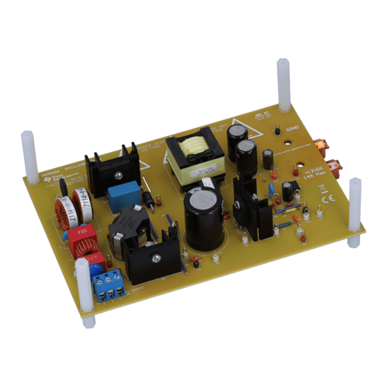
PFCLLCSREVM034
Texas Instruments PFCLLCSREVM034 Manuals
Manuals and User Guides for Texas Instruments PFCLLCSREVM034. We have
1
Texas Instruments PFCLLCSREVM034 manual available for free PDF download: User Manual
Texas Instruments PFCLLCSREVM034 User Manual (30 pages)
Brand:
Texas Instruments
| Category:
Motherboard
| Size: 3 MB
Table of Contents
Table of Contents
2
Trademarks
7
Introduction
7
Description
7
Typical Applications
7
Features
7
Performance Specifications
8
PFCLLCSREVM034 Electrical Performance Specifications
8
Schematic Diagram
9
PFCLLCSREVM034 Schematic Diagram: PFC Section
9
PFCLLCSREVM034 Schematic Diagram: LLC Section
10
Test Points
11
Terminals
11
List of Terminals
11
Test Setup
12
Test Equipment
12
Recommended Test Setup
12
PFCLLCSREVM034 Test Setup Diagram
12
Performance Data and Typical Characteristics Curves
13
Efficiency
13
Efficiency Vs Output Current
13
Efficiency Measurements
13
Standby Power
14
Power Factor
14
Power Factor Vs Output Power
14
Total Harmonic Distortion
15
THD Vs Output Current
15
Load Regulation
16
Output Voltage Vs Output Current
16
Startup
17
115Vrms Input Startup into no Load (CH1=PFC Output; CH2=AC Input; CH3=LLC Output)
17
115Vrms Startup into Full Load (CH1=PFC Output; CH2=AC Input; CH3=LLC Output)
18
115Vrms Startup into Full Load Zoomed in (CH1=PFC Output; CH2=AC Input; CH3=LLC Output)
18
230Vrms Input Startup into no Load (CH1=PFC Output; CH2=AC Input; CH3=LLC Output)
19
230Vrms Startup into no Load Zoomed in (CH1=PFC Output; CH2=AC Input; CH3=LLC Output)
19
230Vrms Input Startup into Full Load (CH1=PFC Output; CH2=AC Input; CH3=LLC Output)
20
230Vrms Startup into Full Load Zoomed in (CH1=PFC Output; CH2=AC Input; CH3=LLC Output)
20
Output Ripple
21
No Load Output Ripple (CH3=LLC Output AC Coupled)
21
Full Load Output Ripple (CH3=LLC Output AC Coupled)
21
Load Transient
22
No Load to Full Load Transient (CH3=LLC Output AC Coupled; Ch4=Output Current)
22
No Load to Full Load Transient Zoomed in (CH3=LLC Output AC Coupled; Ch4=Output Current)
22
LLC Loop Response
23
9.10 Steady State Waveforms
23
115Vrms Input, Full Load (CH1=PFC Switch Node; CH4=PFC Inductor Current)
23
230Vrms Input, Full Load (CH1=PFC Switch Node; CH4=PFC Inductor Current)
24
10Ma Load (CH1=LLC Switch Node; CH4=LLC Resonant Current)
24
9.11 X Capacitor Discharge
25
Assembly Drawings
25
Top Layer Assembly
25
Bottom Layer Assembly
26
Bottom Layer Copper
26
List of Materials
27
Advertisement
Advertisement
Related Products
Texas Instruments PFC23338EVM-107
Texas Instruments PGA308
Texas Instruments PCM5122/42EVM-U
Texas Instruments PS62510EVM-168
Texas Instruments PCM1841Q1EVM-PDK
Texas Instruments PCM1809
Texas Instruments PCM182 Q1 Series
Texas Instruments PWR730
Texas Instruments PGA4311
Texas Instruments PCM1803AEVM
Texas Instruments Categories
Motherboard
Control Unit
Microcontrollers
Computer Hardware
Calculator
More Texas Instruments Manuals
Login
Sign In
OR
Sign in with Facebook
Sign in with Google
Upload manual
Upload from disk
Upload from URL