Advertisement
Quick Links
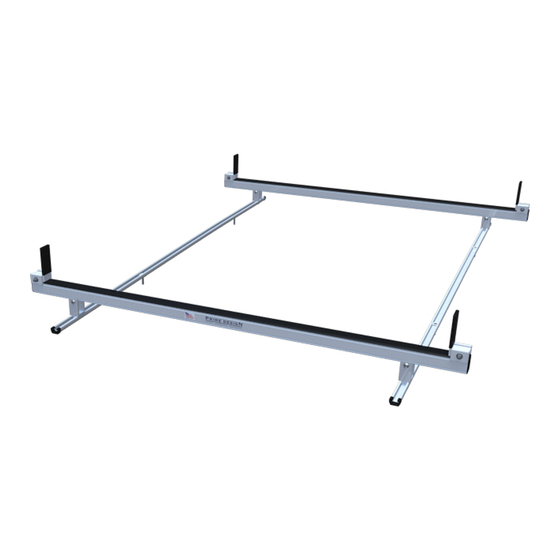
2014+ Ram ProMaster Low/High Roof Base Mounting Kit
Page 2
Packaging Contents
Pages 3-7
L1H1 (118" Wheelbase)
Pages 8-12
L2H1 (136" Wheelbase)
Pages 13-16
L2H2 (Med Roof/136" Wheelbase)
Pages 17-21
L4H2 (159" Wheelbase)
Pages 22-26
L5H2 (159+" Wheelbase, Ext.)
PRIME DESIGN, A SAFE FLEET BRAND ▪ Address: 1689 Oakdale Avenue #102, West St Paul, Minnesota 55118
Toll Free: 1.8.PRIME.RACK ▪ Fax: 651-552-1799 ▪ Email: info@primedesign.net ▪ Website: www.primedesign.net
Advertisement

Related Manuals for Safe Fleet Prime Design ProMaster FBM-1007-BLK


Summary of Contents for Safe Fleet Prime Design ProMaster FBM-1007-BLK
- Page 1 Pages 17-21 L4H2 (159” Wheelbase) Pages 22-26 L5H2 (159+” Wheelbase, Ext.) PRIME DESIGN, A SAFE FLEET BRAND ▪ Address: 1689 Oakdale Avenue #102, West St Paul, Minnesota 55118 Toll Free: 1.8.PRIME.RACK ▪ Fax: 651-552-1799 ▪ Email: info@primedesign.net ▪ Website: www.primedesign.net...
-
Page 2: Contents Overview
CONTENTS OVERVIEW TWO & THREE CROSSBAR CONFIGURATIONS NOTE: This Manual contains information covering two and three Crossbar configurations. If your model is a two Crossbar configuration, disregard all Center Crossbar installation information. 1—FBM-1007-BLK-BLK ......... (Qty 1) Channels, 117.50” w/Hardware Kits 24”... - Page 3 L1H1 (118.00”) FBM ASSEMBLY SEQUENCE ERGORACK CONFIGURATION ALURACK CONFIGURATION NOTE: Base, Rotation, Crossbar, and Side Rail features are shown for illustrative purposes only. These features are not included with this Base Mounting Kit, and must be purchased separately. CHANNEL MOUNTINGS NOTE: Channel Mountings must be disassembled for installation onto the vehicle’s roof.
- Page 4 Slide and position the Channel Connector into the Mounting Body as shown, then screw the 30MM Flat Head bolt into the Base Puller. Slide Channels onto Mounting Brackets F r o 66” 42” R e a Do not tighten Torque to 80 in-lbs Slide the upper and lower Channel Connectors into...
-
Page 5: Mounting Brackets
MOUNTING BRACKETS Using the supplied fastening hardware, attach the Crossbar Mounting Brackets into the Aluminum Strip Nuts placed into the Channels at Step 2.1 Slide the Aluminum Strip Nuts into each end of the Channels, and attach the Channel Caps 3 Crossbar models: Position the center *2 &... - Page 6 CROSSBARS (ERGORACK) CROSSBAR ADJUSTMENT Shown with LH Base, and RH Rotation for illustrative purposes only Front Even Even h i c F r o Center (if equipped) Same as Front h i c Rear Even Even Torque all of these Crossbar Clamp nuts to 90 in-lbs Verify the specified...
- Page 7 CROSSBAR CROSSBARS (ALURACK) ADJUSTMENT Shown with L1H1 AluRack for illustrative purposes only h i c F r o Center 3A.1 h i c Torque all of these 3A.2 Crossbar Clamp nuts to 90 in-lbs. 3A.3 Verify the specified distance from the ends of both Mounting Bracket to the ends of both Channels.
- Page 8 L2H1 (136.00”) FBM ASSEMBLY SEQUENCE ERGORACK CONFIGURATION ALURACK CONFIGURATION NOTE: Base, Rotation, Crossbar, and Side Rail features are shown for illustrative purposes only. These features are not included with this Base Mounting Kit, and must be purchased separately. CHANNEL MOUNTINGS NOTE: Channel Mountings must be disassembled for installation onto the vehicle’s roof.
- Page 9 Slide and position the Channel Connector into the Mounting Body as shown, then screw the 30MM Flat Head bolt into the Base Puller. Slide Channels onto Mounting Brackets F r o 66” 42” R e a Do not tighten Torque to 80 in-lbs Slide the upper and lower Channel Connectors into...
- Page 10 MOUNTING BRACKETS Using the supplied fastening hardware, attach the Crossbar Mounting Brackets into the Aluminum Strip Nuts placed into the Channels at Step 2.1 Slide the Aluminum Strip Nuts into each end of the Channels, and attach the Channel Caps 3 Crossbar models: *2 &...
- Page 11 CROSSBARS (ERGORACK) CROSSBAR ADJUSTMENT Shown with LH Base, and RH Rotation for illustrative purposes only Even Front Even h i c F r o Center (if equipped) Same as Front h i c Even Rear Even Torque all of these Crossbar Clamp nuts to 90 in-lbs Verify the specified...
- Page 12 CROSSBAR CROSSBARS (ALURACK) ADJUSTMENT Shown with L2H1 AluRack for illustrative purposes only h i c F r o Center 3A.1 h i c Torque all of these 3A.2 Crossbar Clamp nuts to 90 in-lbs. 3A.3 Verify the specified distance from the ends of both Mounting Bracket to the ends of both Channels.
- Page 13 L2H2 (136.00”) FBM ASSEMBLY SEQUENCE–ALURACK ONLY ALURACK ONLY CONFIGURATION NOTE: Base, Rotation, Crossbar, and Side Rail features are shown for illustrative purposes only. These features are not included with this Base Mounting Kit, and must be purchased separately. CHANNEL MOUNTINGS NOTE: Channel Mountings must be disassembled for installation onto the vehicle’s roof.
- Page 14 Slide and position the Channel Connector into the Mounting Body as shown, then screw the 30MM Flat Head bolt into the Base Puller. Slide Channels onto Mounting Brackets F r o 66” 42” R e a Do not tighten Torque to 80 in-lbs Slide the upper and lower Channel Connectors into...
- Page 15 MOUNTING BRACKETS Using the supplied fastening hardware, attach the Crossbar Mounting Brackets into the Aluminum Strip Nuts placed into the Channels at Step 2.1 Slide the Aluminum Strip Nuts into each end of the Channels, and attach the Channel Caps F r o F r o R i g...
- Page 16 CROSSBAR CROSSBARS (ALURACK) ADJUSTMENT Shown with L2H2 AluRack for illustrative purposes only h i c F r o Center 3A.1 Torque all of these h i c 3A.2 Crossbar Clamp nuts to 90 in-lbs. 3A.3 Verify the specified distance from the ends of both Mounting Bracket to the ends of both Channels.
- Page 17 L4H2 (159.00”) FBM ASSEMBLY SEQUENCE ERGORACK CONFIGURATION ALURACK CONFIGURATION NOTE: Base, Rotation, Crossbar, and Side Rail features are shown for illustrative purposes only. These features are not included with this Base Mounting Kit, and must be purchased separately. CHANNEL MOUNTINGS NOTE: Channel Mountings must be disassembled for installation onto the vehicle’s roof.
- Page 18 Slide and position the Channel Connector into the Mounting Body as shown, then screw the 30MM Flat Head bolt into the Base Puller. Slide Channels onto Mounting Brackets F r o Do not tighten R e a Torque to 80 in-lbs NOTE: An Aluminum Strip Nut must be inserted into the 24”...
- Page 19 MOUNTING BRACKETS Set to distances shown below, then torque Mounting 1.11 Bracket nuts loosened at Step 1.5 to 80 in-lbs Slide the remaining Aluminum Strip Nuts into each end of the Channels, and attach the Channel Caps Flush to rear 41.93”...
- Page 20 CROSSBARS (ERGORACK) Shown with LH Base, and RH Rotation for illustrative purposes only h i c F r o h i c Do not mount the Crossbars to this FBM system at this time. Refer to the respective FEA Assembly Manual(s) included with your chosen rack configuration features.
- Page 21 CROSSBAR CROSSBARS (ALURACK) ADJUSTMENT Shown with L4H2 AluRack for illustrative purposes only h i c F r o Center 3A.1 Torque all of these 3A.2 Crossbar Clamp nuts h i c to 90 in-lbs. 3A.3 Verify the specified distance from the ends of both Mounting Bracket to the ends of both Channels.
- Page 22 L5H2 (159.00”+) FBM ASSEMBLY SEQUENCE ERGORACK CONFIGURATION ALURACK CONFIGURATION NOTE: Base, Rotation, Crossbar, and Side Rail features are shown for illustrative purposes only. These features are not included with this Base Mounting Kit, and must be purchased separately. CHANNEL MOUNTINGS NOTE: Channel Mountings must be disassembled for installation onto the vehicle’s roof.
- Page 23 Slide and position the Channel Connector into the Mounting Body as shown, then screw the 30MM Flat Head bolt into the Base Puller. Slide Channels onto Mounting Brackets F r o Do not tighten R e a Torque to 80 in-lbs Slide the upper and lower Channel Connectors into Channels and align holes...
- Page 24 MOUNTING BRACKETS Using the supplied fastening hardware, attach the Crossbar Mounting Brackets into the Aluminum Strip Nuts placed into the Channels at Step 2.1 Slide the Aluminum Strip Nuts into each end of the Channels, and attach the Channel Caps 3 Crossbar models: *2 &...
- Page 25 CROSSBARS (ERGORACK) CROSSBAR ADJUSTMENT Shown with LH Base, and RH Rotation for illustrative purposes only h i c F r o Even Front Even Center (if equipped) Same as Front h i c Even Rear Even Torque all of these Crossbar Clamp nuts to 90 in-lbs Verify the specified...
- Page 26 CROSSBAR CROSSBARS (ALURACK) ADJUSTMENT Shown with L5H2 AluRack for illustrative purposes only h i c F r o 3A.1 Center h i c Torque all of these 3A.2 Crossbar Clamp nuts to 90 in-lbs. 3A.3 Verify the specified distance from the ends of both Mounting Bracket to the ends of both Channels.
- Page 27 CENTER CROSSBAR MOUNTS FOR 2 CROSSBAR ERGORACK MODELS ONLY Place the center Crossbar Mounts into the vehicle’s glove box for future use. Prime Design Limited Warranty. Seller’s sole and exclusive warranty (and Buyer’s sole and exclusive remedy and Seller’s entire liability for any breach thereof) with respect to the Goods is set forth in the Limited Warranty document available at primedesign.net/warranty-liability (the “Prime Design Limited Warranty”).
- Page 28 USAM-FBM1007BLK-US01 Rev-A 1019...
Need help?
Do you have a question about the Prime Design ProMaster FBM-1007-BLK and is the answer not in the manual?
Questions and answers