Advertisement
Advertisement

Related Manuals for Robertshaw RS10420T


Summary of Contents for Robertshaw RS10420T
- Page 1 RS10420T Installation Manual...
- Page 3 INSTALLATION MANUAL The Robertshaw Programmable WiFi Thermostat allows you to control the temperature ® anytime and anywhere. It features a large backlit display and LCD touchscreen for ease of operation. Compatible with any IOS or Android Smartphone. Thermostat System Types IMPORTANT SAFETY INFORMATION...
-
Page 4: Table Of Contents
INSTALLATION MANUAL Table of Contents Page Installation Location Thermostat Quick Reference Wiring Wiring Diagrams 8-10 Installer Setup 11-16 Programming 17-20 Setting Up WiFi Connection and App Specifications Temperature Display Range ......32°F to 99°F (0°C to 40°C) Temperature Control Range ....... 41°F to 90°F (5°C to 32°C) Load Rating .......... -
Page 5: Installation Location
INSTALLATION LOCATION Wallplate Installation 1 Horizontal Mount Caution: 2 Vertical Mount Electrical Hazard Disconnect power before installing this product. Failure to do so can cause electric shock or equipment damage. Mercury Notice This product is mercury-free. However, if this product is replacing a control which contains mercury, it needs to be disposed of properly. - Page 6 INSTALLATION LOCATION Mounting Thermostat Align the 4 tabs on the faceplate with the corresponding slots on the back of the thermostat, then push gently until the WAKE thermostat snaps into place. Set At SYSTEM Install the thermostat 4 to 5 feet above the Heat floor in an area with good air circulation Auto...
-
Page 7: Thermostat Quick Reference
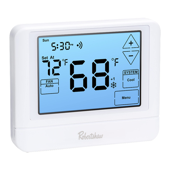
THERMOSTAT QUICK REFERENCE Getting to know your thermostat Sun Mon Tue Wed Thu Fri Sat Sun Mon Tue Wed Thu Fri Sat WAKE LEAVE RETURN SLEEP WAKE LEAVE RETURN SLEEP Set At Set At SYSTEM HOLD SYSTEM Heat Auto HOLD Heat Off Cool Auto... -
Page 8: Wiring
WIRING Terminal Designations CONVENTIONAL COOL MODE COOL MODE HEAT MODE HEAT MODE – – HVAC STAGE 1 STAGE 2 STAGE 1 STAGE 2 1H / 1C HEAT 2 2H / 1C AUX 1 HEAT PUMP AUX 2 HEAT PUMP REVERSING HEAT 2 HEAT 3 REVERSING... - Page 9 WIRING Notes Wire Specifications Use 18- to 22-gauge thermostat wire. Shielded wire is not required. Emergency Heat Operation: In many heat pump systems with no emergency heat relay, a jumper can be installed between E and W2 to turn thermostat into a single stage control for Emergency Heat Operation.
-
Page 10: Wiring Diagrams
WIRING DIAGRAMS Power supply Factory-installed jumper. Remove only when installing on 2-transformer systems Use either O or B terminals for reversing valve 24 VAC common connection Typical 2H/2C System: 1 Transformer (HOT) COMPRESSOR Typical Cool-Only System With Fan RELAY HEAT RELAY (HOT) FAN RELAY COMPRESSOR... - Page 11 WIRING DIAGRAMS Typical Heat Only System With Fan Note: In many systems with no emergency heat relay, a jumper can be installed (HOT) between E and W2. HEAT RELAY FAN RELAY...
- Page 12 WIRING DIAGRAMS Typical 3H/2C or 2H/1C Heat Pump System (HOT) COMPRESSOR RELAY COOL REVERSING EMERGENCY VALVE HEAT RELAY HEAT REVERSING VALVE FAN RELAY AUXILIARY HEAT RELAY COMPRESSOR RELAY 2 Typical 2H/2C System: 2 Transformers REMOVE JUMPER (HOT) (HOT) COMPRESSOR RELAY HEAT RELAY FAN RELAY HEAT RELAY 2 COMPRESSOR...
-
Page 13: Installer Setup
INSTALLER SETUP 1. Press MENU. 2. Press and hold TECHNICIAN SETUP for 3 seconds. 3. Configure the installer options as desired using the table below. 4. Use to change settings and the NEW STEP or PREV STEP to move from one step to another. - Page 14 INSTALLER SETUP Settings Display Adjustment Options Default The minimum compressor run time can be adjusted from OFF to 3, 4, or Minimum The installer can select the 5 minutes. If 3, 4, or 5 is selected, minimum run time for the Compressor the compressor will run for at least compressor to help protect the...
- Page 15 INSTALLER SETUP Settings Display Adjustment Options Default The heating differential is factory preset at 0.4°. This means that whenever the room temperature Heating cools by 0.4° from the temperature The heating differential setting is setting, the heating system will turn adjustable from 0.2°F to 2°F.
- Page 16 INSTALLER SETUP Settings Display Adjustment Options Default The cooling fan delay can be set to OFF, 15, 30, 60 or 90 seconds. The cooling fan delay setting delays If 15, 30, 60 or 90 is selected, the the fan from coming on in cool Cooling Fan fan will not turn on for at least the mode and keeps it running after...
- Page 17 INSTALLER SETUP Settings Display Adjustment Options Default 12 Hour 12 or 24 to select Select a 12 or 24 hour clock setting. Clock Hour Clock 12 or 24 hour clock. Select GAS or ELEC depending on GAS or ELEC Operation the type of furnace.
- Page 18 INSTALLER SETUP Settings Display Adjustment Options Default If ON is selected, The thermostat can be configured the beep will sound. Beep to make an audible beep when any If OFF is selected, key is pressed. the beep will be silenced. This step shows the MAC address MACID of WiFi module.
-
Page 19: Programming
PROGRAMMING Programming Notes Differential Setting The second stage will turn ON at 2x the differential setting and OFF at 1x the differential setting. For example, if the differential setting is 0.5° for heating and the thermostat is set at 70°F, the first stage will turn on at 69.5°F. The second stage will turn on at 69°F and turn off at 69.5°F. - Page 20 PROGRAMMING Set Time of day and day of the week (If using programming) 1. Press the MENU button. 2. Press SET TIME. 3. Day of the week will be flashing. Use to select the current day of the week. 4. Press NEXT. 5.
- Page 21 PROGRAMMING 1. Select HEAT or COOL using the system key. Note: Heat and cool need to be programmed separately. 2. Press MENU (If menu does not appear first, press RUN SCHED). 3. Press SET SCHED. Note: Monday will be displayed and the WAKE icon is shown.
- Page 22 PROGRAMMING Default Program This thermostat is pre-programmed for energy saving operation. The default program is below: Default Program Day of the Set-Point Temperature Set-Point Temperature Time Events Week (Heat) (Cool) Weekday 6 a.m. 70°F (21°C) 75°F (24°C) Wake 8 a.m. 62°F (17°C) 83°F (28°C) Leave...
-
Page 23: Setting Up Wifi Connection And App
SETTING UP WIFI CONNECTION AND APP The Robertshaw RS10420T Programmable WiFi Thermostat works with the Robertshaw Thermostat App which is available for IOS and Android platforms. Users can download the App from the Apple store or Google Play. Use Phone to Scan for App... - Page 24 Customer Service +1.800.304.6563 Technical Service +1.800.445.8299 Use Phone Year HVACCustomerService@robertshaw.com to Scan for Limited www.robertshaw.com • 352-00301-001 352-00308-001 Rev. B Warranty Info Warranty © 2021 Robertshaw Controls Company. Robertshaw is a trademark of Robertshaw Controls Company. ®...
- Page 25 The following guide will enable you to set up your thermostat quickly. Configuration is set through WiFi networks, one being your home network, the other programmed into the thermostat. Bluetooth is not used. Apple iOS is shown but is the same for Android set up and use. Add Device (RS10420T) Step 1...
- Page 26 Add Device (RS10420T) Step 5 Step 6 Step 7 Step 8 Make sure the RS10420T is Tap Menu in the lower right. Touch the Technician button Touch the Fan button for 3-5 turned on. Tap Yes. for 3-5 seconds, as shown.
- Page 27 Step 10 Step 11 Step 12 Select your WiFi network, and Tap Yes. Go to phone settings and Make sure to allow ROBERTSHAW add password. select the “therm_” network. to access “Local Network”. Navigate back to app to continue configuration.
- Page 28 Pro-Series Quick Set up Guide Android and Apple Platforms Add Device (RS10420T) Step 13 Step 14 Wait for your phone to bind to After configuration is completed thermostat. tap Ok. Technical Service 800.445.8299...
- Page 29 Pro-Series Quick Set up Guide Android and Apple Platforms Using Your Thermostat (RS10420T) Step 1 Step 2 Step 3 Step 4 Tap the three green dots to You can edit your device The active RS10420T displays Tap gear to see settings.
- Page 30 Pro-Series Quick Set up Guide Android and Apple Platforms Using Your Thermostat (RS10420T) Step 5 Step 6 Step 7 Step 8 To select control mode tap Select Heat or Cool to adjust Tap the Fan icon on the bottom Tap More icon on the bottom menu Heat icon.
- Page 31 Pro-Series Quick Set up Guide Android and Apple Platforms Using Your Thermostat (RS10420T) Step 9 Step 10 Step 11 Tap Schedule, then Heat. Program Tap Cool to program cooling Tap Auto to program both heat and wake, leave, return and sleep daypart temperatures by the day.
- Page 32 8. When you see the connected page, it means the Alexa account is linked with the “Robertshaw” account 9. Alexa will now begin looking for devices to connect 10. You can now control your Robertshaw thermostat using your Alexa device In the Robertshaw app, edit your Download Alexa App to your device name here.
Need help?
Do you have a question about the RS10420T and is the answer not in the manual?
Questions and answers
Above the number 5 on getting to know your thermostat, system operations indicators, what is the +1, +2 and +3, beside and under **** symbol and what do they mean.
The +1, +2, and +3 indicators above the number 5 in the system operations section of the Robertshaw RS10420T thermostat refer to HVAC system stages. Specifically:
- +1 indicates Stage 1 operation (e.g., first stage heating or cooling).
- +2 indicates Stage 2 operation (e.g., second stage heating or cooling).
- +3 is not explicitly defined in the context but may suggest additional system stages or modes depending on configuration.
These indicators show which stage of the HVAC system is currently active.
This answer is automatically generated