Robertshaw RS8110 Installation Manual
Hide thumbs
Also See for RS8110:
- Operation manual (12 pages) ,
- Installation manual (20 pages) ,
- Operation manual (12 pages)
Advertisement
Quick Links
Advertisement

Related Manuals for Robertshaw RS8110


Summary of Contents for Robertshaw RS8110
- Page 1 RS8110 Installation Manual...
-
Page 3: Table Of Contents
INSTALLATION MANUAL Thank you for purchasing a Robertshaw thermostat. ® This manual will describe how to install and test the Robertshaw RS8110 thermostat. Thermostat System Types Power Options Battery Power Gas, Oil, or Electric Heat with Air Conditioning Hardwire (Common Wire) -
Page 4: Installation Location
INSTALLATION LOCATION Install the thermostat 4 to 5 feet above the floor in an area with good air circulation and average temperature. For new installations, mount thermostat on an inside wall, 4-5 feet above the floor. Do not install the thermostat in the following locations: •... -
Page 5: Thermostat Quick Reference
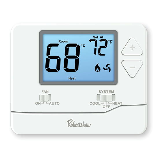
THERMOSTAT QUICK REFERENCE Getting to know your thermostat Displays the user selected Set At Room Set At Room set-point temperature. System operation indicators: The COOL, HEAT or FAN icon will Cool display when the COOL, HEAT or SYSTEM FAN is on. COOL HEAT AUTO... -
Page 6: Wallplate Installation
WALLPLATE INSTALLATION Mercury Notice: Caution: This product is mercury-free. However, Electrical Hazard. if this product is replacing a control Disconnect power before installing this which contains mercury, it needs to be product. Failure to do so can cause disposed of properly. Contact your electric shock or equipment damage. -
Page 7: Wiring
WIRING 1 Turn Off Power to Heating/Cooling System Heating/cooling system Circuit breaker power switch 2 Remove Old Thermostat Remove old thermostat but leave wallplate with wires attached. Do not remove wallplate yet Terminal designation... - Page 8 WIRING 4 Separate Wallplate from New Thermostat 3 Label Wires with Tags Remove wallplate from the new thermostat and Label the wires using the supplied wire labels as mount onto wall. you disconnect them. Wiring Labels Apply these wiring labels to each wire with the appropriate terminal designation as you remove it from the existing thermostat.
- Page 9 WIRING 5 Separate Wallplate from New Thermostat Mount the new wallplate using the included screws and anchors. Drill 3/16-in. holes for drywall Drill 3/16-in. holes for plaster...
- Page 10 WIRING 6 Connect Wires Simply match wire labels. If labels do not match letters on the thermostat, check “Alternate Wiring (Conventional Systems)” on page 9 and connect to terminal as shown (see notes, below). Remove metal jumper if you have both R and RC wires Insert wires and tighten Screw...
- Page 11 WIRING Alternate Wiring (Conventional Systems) If labels do not match letters on the thermostat, check the chart below and connect to terminal as shown here (See notes, below). Remove metal jumber if wires will be connected to both RH/R and RC terminals. If a 24 volt common wire is present (typically labeled C or X) connect it to the C terminal.
- Page 12 WIRING Terminal Designations Heat relay Fan relay Compressor relay Heat pump reversing valve energized in cooling 24 volt cooling transformer RH/R 24 volt heating transformer OR 24 volt power terminal if a common wire is present Heat pump reversing valve energized in heating 24 volt common terminal Notes: RH &...
- Page 13 WIRING Power supply. Factory-Installed jumper. Remove only when installing on 2-transformer systems. Use either O or B terminals for reversing valve. Heat pump application ONLY. Use a small piece of wire (not supplied) to connect W and Y terminals. Set fan operation switch to either gas or electric based on your system. Optional 24 VAC common connection not to be used when powering thermostat with batteries.
- Page 14 WIRING Typical 1H/1C heat pump system Typical heat-only system L1 (HOT) L1 (HOT) COMPRESSOR RELAY COOL REVERSING VALVE FAN RELAY HEAT REVERSING HEAT RELAY VALVE Typical heat-only system with fan Typical cool-only system L1 (HOT) L1 (HOT) COMPRESSOR RELAY FAN RELAY HEAT RELAY FAN RELAY Tips:...
-
Page 15: Installer Setup Menu
INSTALLER SETUP MENU Gas or Electric Setup Select GAS or ELEC depending on the type of furnace. If ELEC is selected, the thermostat will operate the fan when the fan relay is connected to the G terminal. Select ELEC or GAS with this switch... - Page 16 INSTALLER SETUP MENU Adjusting the Differential (Also called Adjusting Room Temperature Calibration, Fahrenheit/Celcius Display and Swing or Cycle rate) Compressor Delay The differential is adjustable, a smaller Wait approximately 10 seconds for Press again to access the differential will cause more frequent the thermostat to return to normal compressor DELAY selection.
-
Page 17: Mounting And Battery Installation
MOUNTING & BATTERY INSTALLATION Mount Thermostat Align the 4 tabs on the subbase with corresponding slots on the back of the thermostat, then push gently until the thermostat snaps in place. Set At Room Cool SYSTEM AUTO COOL HEAT Battery Installation Battery installation is optional if used with AC power (the C terminal is connected). -
Page 18: Specifications
SPECIFICATIONS Temperature Display Range ....41°F to 95°F (5°C to 35°C) Temperature Control Range ....44°F to 90°F (7°C to 32°C) Load Rating ........1 amp per terminal, 1.5 amp maximum all terminals combined Display Accuracy ........± 1°F Differential...........Heating is adjustable from 0.2°F to 2.0°F Cooling is adjustable from 0.2°F to 2.0°F Power Source ........18 to 30 VAC, NEC Class II, 50/60 Hz for hardwire (common wire) Battery power from 2 AAA Alkaline batteries... - Page 20 Customer Service +1.800.304.6563 Technical Service +1.800.445.8299 Use Phone Year HVACCustomerService@robertshaw.com to Scan for Limited 352-00301-001 Rev. B www.robertshaw.com • 352-00301-001 Warranty Info Warranty © 2021 Robertshaw Controls Company. Robertshaw is a trademark of Robertshaw Controls Company. ®...
Need help?
Do you have a question about the RS8110 and is the answer not in the manual?
Questions and answers
Installation
To install the Robertshaw RS8110 thermostat:
1. Choose Location:
- Mount on an inside wall 4–5 feet above the floor.
- Ensure good air circulation and average temperature.
- Avoid locations behind doors, in corners, near vents, in direct sunlight, on outside walls, or near heat/steam sources.
2. Separate Wallplate:
- Remove the wallplate from the thermostat.
3. Mount Wallplate:
- Use included screws and anchors.
- Drill 3/16" holes (for drywall or plaster).
- For vertical mount: screws on top and bottom.
- For horizontal mount: screws on left and right.
4. Connect Wires:
- Match wire labels to terminal designations.
- If labels differ, refer to the alternate wiring chart.
- Remove metal jumper if using both RH/R and RC wires.
- If a 24V common wire (C or X) is present, connect to C terminal.
- Tighten wire screws securely.
5. Install Batteries:
- Use the easy-change battery door to insert batteries (replace when low battery icon appears).
6. Attach Thermostat to Wallplate:
- Snap the thermostat onto the wallplate securely.
7. Restore Power:
- Reconnect power to the system.
Do not jumper across gas valve or control terminals to test—this can damage the thermostat and void the warranty.
This answer is automatically generated