Table of Contents
Advertisement
Quick Links
Service Manual
Microwave Oven
Model: KOR-6C0B5S
Caution
: In this Manual, some parts can be changed for improving,
their performance without notice in the parts list. So, if you
need the latest parts information, please refer to PPL(Parts
Price List) in Service Information Center (http://svc.dwe.co.kr).
DAEWOO ELECTRONICS CORP.
http : //svc.dwe.co.kr
S/M No. : R6C0B5S001
Feb. 2003
Advertisement
Table of Contents

Related Manuals for Daewoo KOR-6C0B5S


Summary of Contents for Daewoo KOR-6C0B5S
- Page 1 S/M No. : R6C0B5S001 Service Manual Microwave Oven Model: KOR-6C0B5S Caution : In this Manual, some parts can be changed for improving, their performance without notice in the parts list. So, if you need the latest parts information, please refer to PPL(Parts Price List) in Service Information Center (http://svc.dwe.co.kr).
-
Page 2: Table Of Contents
PRECAUTIONS TO BE OBSERVED BEFORE AND DURING SERVICING TO AVOID POSSIBLE EXPOSURE TO EXCESSIVE MICROWAVE ENERGY (a) Do not operate or allow the oven to be operated with the door open. (b) Make the following safety checks on all ovens to be serviced before activating the magnetron or other micro- wave source, and make repairs as necessary: (1) Interlock operation, (2) Proper door closing, (3) Seal and sealing surfaces (arcing, wear, and other damage), (4) Damage to or loosening of hinges and latches, (5) Evidence of dropping or abuse. -
Page 3: Safety And Precautions
SAFETY AND PRECAUTIONS 1. FOR SAFE OPERATION Damage that allows the microwave energy (that cooks or heats the food) to escape will result in poor cooking and may cause serious bodily injury to the operator. IF ANY OF THE FOLLOWING CONDITIONS EXIST, OPERATOR MUST NOT USE THE APPLIANCE. (Only a trained service personnel should make repairs.) (1) A broken door hinge. -
Page 4: Specifications
SPECIFICATIONS MODEL KOR-6C0B5S POWER SUPPLY 230V-50Hz, SINGLE PHASE WITH EARTHING MICROWAVE 1200W POWER GRILL CONSUMPTION COMBINATION MICROWAVE ENERGY OUTPUT 800W MICROWAVE FREQUENCY 2450MHz OUTSIDE DIMENSIONS (W X H X D) 465 x 279 x 365 mm (18.3 x 11.0 x 14.4 in) CAVITY DIMENSIONS (W X H X D) 290 x 220 x 306 mm (11.4 x 8.7 x 12.0 in) -
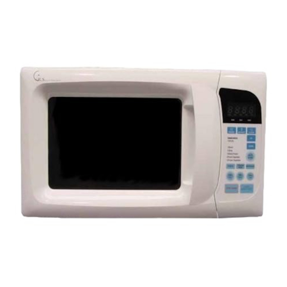
Page 5: External View
EXTERNAL VIEW 1. OUTER DIMENSION... -
Page 6: Feature Diagram
2. FEATURE DIAGRAM 1 DOOR SEAL Door seal maintains the microwave within the oven cavity and prevents microwave leakage. 2 DOOR HOOK When the door is closed, it will automatically lock shut. If door is opened while oven is operating, magnetron tube will immediately stop operating. -
Page 7: Control Panel
3. CONTROL PANEL 1 Display - Cooking time, power level, indicators and the current time are displayed. 2 Power - Used to set power level. 3 Defrost - Used to defrost foods for time. 4 Clock - Used to set clock. 5 Up - Used to add time to cooking. -
Page 8: Installation
• This appliance is supplied with cable of special type, which, if damaged, must be repaired with cable of same type. Such a cable can be purchased from DAEWOO and must be installed by a qualified person. 6. Examine the oven after unpacking for any damage such as: A misaligned door, broken door or a dent in cavity. -
Page 9: Operations And Functions
OPERATIONS AND FUNCTIONS 11. Connect the main lead to an electrical outlet. 12. After placing the food in a suitable container, open the oven door and put it on the glass tray. The glass tray must always be in place during cooking. 13. -
Page 10: Disassembly And Assembly
DISASSEMBLY AND ASSEMBLY Cautions to be observed when trouble shooting. Unlike many other appliances, the microwave oven is high-voltage, high-current equipment. It is completely safe during normal operation. However, carelessness in servicing the oven can result in an electric shock or possible danger from a short circuit. You are asked to observe the following precautions carefully. - Page 11 1. To remove cabinet 1) Remove three screws on cabinet back. 2) Push the cabinet backward. 2. To remove door assembly 1) Remove two screws which secure the stopper hinge top. 2) Remove the door assembly from top plate of cavity. 3) Reverse the above for reassembly.
- Page 12 3512206400 FRAME DOOR HIPS 3517007300 BARRIER-SCREEN*0 PET T0.125 3515204100 STOPPER SINGE *T AS KOR-63150S 3511719600 DOOR WELD AS KOR-6C0B5S 3517002800 BARRIER-SCREEN *I T0.1 3512300210 GASKET DOOR 3513100730 HOOK 3515101320 SPRING HOOK HSW-3 (1) Remove the gasket door from door weld as.
- Page 13 4. Method to reduce the gap between the door seal and the oven front surface. (1) To reduce gap located on part ‘A’ Loosen a screws on stopper hinge top, and then push the door to contact the door seal to oven front surface. Tighten two screws.
- Page 14 Information Center (http://svc.dwe.co.kr). 5. To remove control panel parts. REF NO. PART CODE PART NAME DESCRIPTION Q’TY REMARK 3518524100 SWITCH MEMBRANE KOR-6C0B5S 3516729000 CONTROL PANEL HIPS PKMPMSZA00 PCB AS KOR-631G0S 7122401211 SCREW TAPPING T2S TRS 4X12 MFZN 1) Remove the screw which secure the control panel, push up two snap fits and draw forward the control panel assembly.
- Page 15 6. To remove high voltage capacitor. 1) Remove a screw which secure the grounding ring terminal of the H.V. diode and the capacitor holder. 2) Remove the H.V. diode from the capacitor holder. 3) Reverse the above steps for reassembly. High voltage circuit wiring 7.
- Page 16 8. To remove wind guide assembly. 1) Remove a screw for earthing. 2) Remove the noise filter from the wind guide. 3) Remove a screw which secure the wind guide assembly. 4) Draw forward the wind guide assembly. 5) Pull the fan from the motor shaft. 6) Remove two screws which secure the motor shaded pole.
-
Page 17: Interlock Mechanism And Adjustment
INTERLOCK MECHANISM AND ADJUSTMENT The door lock mechanism is a device which has been specially designed to completely eliminate microwave radiation when the door is opened during operation, and thus to perfectly prevent the danger resulting from the leakage of microwave. (1) Primary interlock switch When the door is closed, the hook locks the oven door. -
Page 18: Trouble Shooting Guide
TROUBLE SHOOTING GUIDE Following the procedure below to check if the oven is defective or not. 1. Check grounding before trouble checking. 2. Be careful of the high voltage circuit. 3. Discharge the high voltage capacitor. 4. When checking the continuity of the switches, fuse or high voltage transformer, disconnect one lead wire from these parts and check continuity with the AC plug removed. - Page 19 CONDITION CHECK RESULT CAUSE REMEDY Replace Defective mag- Outlet has Check continuity of magnetron Continuity netron proper volt- age Fuse does not Replace Defective mag- blow. Check continuity of Continuity noise filter board netron Replace Open power sup- Check continuity of Continuity ply cord power supply cord...
- Page 20 (TROUBLE 3) No microwave oscillation even though fan motor rotates. CONDITION CHECK RESULT CAUSE REMEDY Continuity microwave Check continuity of high oscillation voltage fuse Replace high voltage fuse Continuity Replace Check continuity of high Defective high voltage capacitor terminals voltage trans- with wires removed former Continuity in...
- Page 21 (TROUBLE 4) The following visual conditions indicate a probable defective touch control circuit or membrane switch assembly. 11. Incomplete segments (1) Segments missing (2) Partical segments missing (3) Digit flickering other than normal display slight flickering (4) “ :0” does not display when power is on. 12.
-
Page 22: Measurement And Test
MEASUREMENT AND TEST 1. MEASUREMENT OF THE MICROWAVE POWER OUTPUT Microwave output power can be checked by indirectly measuring the temperature rise of a certain amount of water exposed to the microwave as directed below. PROCEDURE 1. Microwave power output measurement is made with the microwave oven supplied at rated voltage and operated at its maximum microwave power setting with a load of 1000±5cc of potable water. -
Page 23: Microwave Radiation Test
2. MICROWAVE RADIATION TEST CAUTION : 1. Make sure to check the microwave leakage before and after repair of adjustment. 2. Always start measuring of an unknown field to assure safety for operating personnel from microwave energy. 3. Do not place your hands into any suspected microwave radiation field unless the safe density level is known. 4. -
Page 24: Component Test Procedure
3. COMPONENT TEST PROCEDURE • High voltage is present at the high voltage terminal of the high voltage transformer during any cooking cycle. • It is neither necessary nor advisable to attempt measurement of the high voltage. • Before touching any oven components or wiring, always unplug the oven from its power source and discharge the capacitor. -
Page 25: Wiring Diagram
WIRING DIAGRAM... -
Page 26: Printed Circuit Board
PRINTED CIRCUIT BOARD 1. CIRCUIT CHECK PROCEDURE 1. Low Voltage Transformer check ¥ The low voltage transformer is located on the P.C.B. ¥ Measuring condition: input voltage : 230V/Frequency : 50Hz Terminal Voltage LOAD NO LOAD AC 25.8 V AC 31.8 V NOTE : 1. - Page 27 Measure Point...
- Page 28 3. When there is no microwave oscillation 1) When touching START pad, oven lamp does not turn on. Fan motor does not rotate, but cook indicator in display comes on. * Cause : RELAY 2 does not operate. refer to Circuit Diagram (Point 3) - Check method POINT STATE...
-
Page 29: Pcb Circuit Diagram
2. PCB CIRCUIT DIAGRAM... -
Page 30: Location No
In this Manual, some parts can be changed for improving, their performance without notice in the parts list. So, if you need the latest parts information, please refer to PPL(Parts Price List) in Service Information Center (http://svc.dwe.co.kr). 3. P.C.B. LOCATION NO. 1) KOR-6C0B5S NAME SYMBOL SPECIFICATION PART CODE Q’TY... -
Page 31: Exploded View And Parts List
EXPLODED VIEW AND PARTS LIST 1. DOOR ASSEMBLY Refer to Disassembly and assembly. 2. CONTROL PANEL ASSEMBLY Refer to Disassembly and assembly. 3. TOTAL ASSEMBLY... - Page 32 So, if you need the latest parts information, please refer to PPL(Parts Price List) in Service Information Center (http://svc.dwe.co.kr). PART CODE PART NAME DESCRIPTION Q'TY 3511719400 DOOR AS KOR-6C0B5S 3516729040 CONTROL PANEL AS KOR-6C0B5S 3510805300 CABINET KOR-61150S 7112401011 SCREW TAPPING...
- Page 33 DAEWOO ELECTRONICS CORP. 686, AHYEON-DONG MAPO-GU SEOUL, KOREA C.P.O. BOX 8003 SEOUL, KOREA TELEX: DWELEC K28177-8 CABLE: “DAEWOOELEC” S/M NO. : R6C0B5S001 PRINTED DATE: Feb. 2003...
Need help?
Do you have a question about the KOR-6C0B5S and is the answer not in the manual?
Questions and answers