Table of Contents
Advertisement
Quick Links
Advertisement
Table of Contents

Related Manuals for Riland MIG 200E


Summary of Contents for Riland MIG 200E
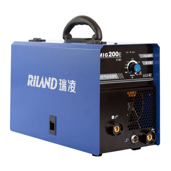
- Page 1 INVERTER WELDER MIG 200E WELDING MACHINE USER MANUAL...
- Page 2 Welcome to a better way of welding! For your own and other people’s safety, please read the manual carefully before operating. And the user manual must always be available near the welding machine. Disclaimer and Warning Thank you for purchasing our products. The content mentioned in this article concerns your safety and legitimate rights and responsibilities.
-
Page 3: Table Of Contents
CONTENTS 1 Safety Guidelines and Precautions........................2 2 Overview.................................. 6 2.1 Product Introduction............................6 2.2 Application Area............................6 2.3 Technical Specifications..........................7 3 Installation................................8 3.1 Installation for MIG (self-shielded) welding.....................8 3.2 Installation for MMA welding........................9 4 Operating Functions.............................10 4.1 Control Panel and label..........................10 4.2 Input/Output Panel............................11 5 Operation................................ -
Page 4: Safety Guidelines And Precautions
1 Safety Guidelines and Precautions Security Definitions It indicates that ignoring safety warnings could result in a major accident, or even death or serious injury. It indicates that ignoring safety warnings could result in minor injuries or property damage. It indicates that ignoring safety warnings could result in equipment failure or damage. - Page 5 Operational Safety Guidelines Electrical Shock Grounded all working materials. Never touch ‘live’ electrical parts. Always repair or replace worn or damaged parts. Wearing dry insulated boots, and dry leather gloves. Disconnect power source before performing any maintenance or service. ...
- Page 6 Welding sparks can cause fire or explosion Do not carry out welding operations in degreasing, cleaning and spraying areas. Do not weld/cut gas-filled pipes, sealing grooves (boxes) and other devices, otherwise explosions or fires are likely to occur. ...
- Page 7 Noise produced during welding can easily cause hearing loss In order to avoid the harm of noise to you and others, please wear the prescribed protective equipment. Matters needing attention in hoisting The power source with strap or hand is prohibited from using strap or hand for lifting.
-
Page 8: Overview
2 Overview Product Introduction This series of welding machines adopts digital inverter technology to convert the current of 50/60Hz frequency into stable welding output current, and adopts Pulse Width Modulation (PWM) technology to obtain constant current characteristics and excellent welding process effect. This series of welding machines can be used for welding carbon steel/stainless steel and other materials,its features are as follows: ... -
Page 9: Technical Specifications
Technical Specifications Type MIG 200E Item Power supply(V) Single phase 220V±15% Frequency(Hz) 50/60 No-load voltage(V) 23.7 (MIG) Rated input current(A) 22.7 (MMA) 60 - 140 (MIG) Output current range (A) 50 - 120 (MMA) 17 - 21 (MIG) Output voltage range (V) 22 - 24.8 (MMA)... -
Page 10: Installation
3 Installation Installation for MIG (self-shielded) welding The welding equipment is equipped with power voltage compensation device. It keeps the machine work normally when power voltage fluctuating ±15% of rated voltage. When using long cable, in order to reduce voltage drop, big section cable is suggested. If the cable is too long, it will affect the performance of arcing and other system function, it is suggested to use the recommend length. -
Page 11: Installation For Mma Welding
Installation for MMA welding There are two welding methods for MMA welding, please choose according to the actual needs. Direct Current Electrode Negative (DCEN): The positive output terminal is connected to the workpiece, and the negative output terminal is connected to the electrode holder. The DCEN is suitable for acid electrode. -
Page 12: Operating Functions
4 Operating Functions Control Panel and label The panel components are described in the following table. Icons Name Description Used to adjust welding current. The power source is synergic designed, After the current is configured, the machine automatically Adjusting Knob matches the feeding speed. -
Page 13: Input/Output Panel
Input/Output Panel Output Terminals Name MIG torch / Negative output terminal Torch switch connector Positive output terminal Input Cable The I determines the input cable, correct plug and input current required for each 1eff machine. Max. effective supply current (I Input cable size 1eff ≤10 A... -
Page 14: Operation
5 Operation Operation Steps for MIG (self-shielded) welding Steps Description After connecting the power supply, the machine is in standby state when the 1 Connect the power pointer points to “stand-by”, and the power indicator lights on When the supply Adjusting Knob is adjusted to the position above “stand-by”. -
Page 15: Operation Steps For Mma Welding
Operation Steps for MMA welding The operations of MMA welding are shown in the table below. Steps Description It is suggested to choose the diameter of electrode according to the 1 Select electrode thickness of the workpiece refer to the following table (Diameter of Electrode). -
Page 16: Environment And Problems
6 Environment and Problems Environment Note: The power source should not be used in rain or snow environment. The recommended external environment for welding is as follows: Please place the power source in a horizontal position. The inclination of the power source shall not exceed 10°. -
Page 17: Problems During Welding
Problems During Welding Fittings, welding materials, environment factor, supply powers maybe have something to do with welding. User must try to improve welding environment. Problems Solutions 1. Examine whether grounding wire clamp contacts with the work pieces well. Arc starting is difficult and easy to break. -
Page 18: Daily Maintenance And Checking
7 Daily Maintenance and Checking Daily Maintenance In maintenance of the unit, take into consideration the rate of use and the environment it is used in. When the unit is used properly and serviced regularly you will avoid unnecessary disturbances in use and production. ... - Page 19 WELDING TORCH unstable arc, please change. Block caused by dirt in the Reason of poor wire sending and tube, and the remains of the unstable arc, (use kerosene to wipe or wire plating lay. change new one.) 1.Pyrocondensation tube broken, Wire sending tube broken O ...
-
Page 20: Trouble Shooting
8 Trouble Shooting IMPORTANT: Only authorised repair agents with valid certifications should carry out repairs and internal servicing. Fault symptom Remedy 1. Make sure the power cord is connected. 2. Check if electric wire net is in work. 3. Some of heat-variable resistors(four) of power panel is damaged, when it happen, general DC14V relay is open or connectors are poor contact. - Page 21 Fault symptom Remedy of main transformer which is on IGBT board then open the machine again: 1) If abnormal indicator is still lit, some of fieldistor of IGBT board are damaged, find out and replace them with same model. 2) If abnormal indicator is not lit: a.Maybe transformer of middle board is damaged, measure inductance volume and Q volume of main transformer by inductance bridge.
-
Page 22: Appendix A Circuit Diagram
Appendix A Circuit Diagram...
Need help?
Do you have a question about the MIG 200E and is the answer not in the manual?
Questions and answers