Table of Contents
Advertisement
Quick Links
Advertisement
Table of Contents

Related Manuals for Riland TIG 315PAC/DC


Summary of Contents for Riland TIG 315PAC/DC
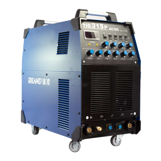
- Page 1 TIG 315P AC/DC WELDING MACHINE USER MANUAL...
- Page 2 Preface This manual includes hardware description and operation introduction of equipment. For your and other people’s safety, please read the manual carefully. Pay attention Pay attention to the words after the signs below. Sign Description The words after this sign means there is great potential danger, which may cause major accident, damage or even death, if it is not followed.
-
Page 3: Table Of Contents
CONTENTS SAFETY WARNING ........................... 4 MACHINE DESCRIPTION ......................... 9 TECHNICAL PARAMETERS TABLE ....................... 10 OPERATION INSTRUCTION ........................14 MAINTENANCE ............................16 NOTES BEFORE CHECKING ......................... 17 NOTES OR PREVENTIVE MEASURES ....................17 QUESTIONS TO BE RUN INTO DURING WELDING ................19 TROUBLESHOOTING AND FAULT FINDING .................. -
Page 4: Safety Warning
SAFETY WARNING ● Please read this manual carefully before using it. ● The safety notes listed in this manual is to ensure correct use of the machine and to keep you and other people from being hurt. ● The machine is safety considered designed, please refer to the safety warning listed in the manual when using it in case of bad accidents. - Page 5 Ask profession person to install, check and maintain the machine. 7 . Please correctly understand the contents of this manual to ensure safety, and ask those professional people with safety knowledge and technique to operate the machine. Danger! Please follow the rules below in case of electric shock: *Any contact of electric parts may cause fatal electric shock or burnt.
- Page 6 6. Use breathe preventive facilities as it will cause poisonous dust and gas when weld shielded steel. Danger! Please follow the below notes to avoid accidents like fire and explode: *Spark and hot workpiece can cause fire. *It may cause fire if the cable is not connected well or when the current circuit of the steel or other workpiece are not connected completely.
- Page 7 Fix the gas cylinder with appropriative holder and other relative parts. 5.Do not put the cylinder under high temperature and sunshine. 6.Do not put your face close to the gas cylinder exit when opening it. 7.Put on the gas shield when not use. 8.Do not put the torch on the gas cylinder or touch the electrode.
- Page 8 Lifting way for the machines with swing ring on the top(φ≤15°) Notes for electromagnetism disturb: 1. It may need extra preventive measures when the power is used in some partial space. 2. Before the installation, please estimate the potential electromagnetism problems of the environment as follows: Upper and down parts of the welding equipments and other nearby power cable, control cable, signal cable and phone cable.
-
Page 9: Machine Description
MACHINE DESCRIPTION The welding machine is a rectifier adopting the most advanced inverter technology. The development of inverter gas-shielded welding equipment profits from the development of the inverter power supply theory and components. Inverter gas-shielded welding power source utilizes high-power component MOSFET to transfer 50/60Hz frequency up to 100KHz, then reduce the voltage and commutate, and output high-power voltage via PWM technology. -
Page 10: Technical Parameters Table
TECHNICAL PARAMETERS TABLE Model TIG 315PAC/DC(with angle) Parameters 3phase 3phase 3phase Power voltage AC380V±15% AC400V±15% AC415V±15% Frequency (Hz) 50/60 17.2(TIG) 16.3 (TIG) 15.7(TIG) Rated input current(A) 15.5(MMA) 14.7(MMA) 14.2(MMA) 12-300(TIG) Output current (A) 15-240(MMA) No-load voltage (V) 22 (TIG) Rated output voltage (V) 29.6(MMA) - Page 11 PANEL FUNCTION INSTRUCTION Front Panel Installation: 2 3 4 Over-current protection light Current meter Remote control switch Over-heat protection light Start current adjustment AC/DC switch TIG/MMA switch Up slope adjustment Pulse frequency change-over switch Pulse wd. adjustment 2T / 4T / Repeat switch Pulse frequency adjustment Peak welding current adjustment Gas connector...
- Page 12 6. According to input voltage grade, connect power cable with power supply box of relevant voltage grade. Make sure so mistake and make sure the voltage difference among permission range. After the above job, installation is finished and welding is available. Appendix:Component type list. Type TIG 315PAC/DC Power switch rated current ≥1.5mm Input side Cable...
- Page 13 Installation diagram (TIG mode) Argon meter Power supply Argon cylinder Earth clamp Workpiece TIG torch Installation diagram (MMA mode) Power supply Earth clamp Workpiece Electrode holder...
-
Page 14: Operation Instruction
OPERATION INSTRUCTION DC Welding Function Instruction Turn on the power switch on the front panel, the current meter shows normally, and the fan begins to work. Turn on valve of the argon cylinder; adjust the current meter according to the need. When the AC/DC alter switch is on the “DC”... - Page 15 AC Welding Function Instruction 1. Put the AC/DC alter switch to the “AC” position as the above1-4 instruction items; there is AC arc welding for the aluminum. 2. Adjust the cleaning pulse width knob according to the oxidation degree of the surface on the work piece: during the AC arc welding, the current alters continuously.
-
Page 16: Maintenance
MMA Welding Function Instruction 1. Put the welding switch to “ Down position”, at this time, “Pulse choosing switch”, “2T/4T switch”, “AC/DC switch” are out of work, only welding current knob can use. 2. Set the welding current according to the work piece thickness. Attached:Relative value for electrode and welding current Electrode diameter Φ1.6... -
Page 17: Notes Before Checking
NOTES BEFORE CHECKING WARNING Blind experiment and careless repair may lead to more problems and make formal check and repair more difficult. When the machine is electrified, the bared parts contain life-threatening voltage. Any direct and indirect touch will cause electric shock, and severe electric shock will lead to death. - Page 18 Do not over load! 2) The operator should remember to watch the max duty current (Response to the selected duty cycle). Welding current should not exceed max duty cycle current. Over-load current will damage and burn up machine. No over voltage! 3)...
-
Page 19: Questions To Be Run Into During Welding
QUESTIONS TO BE RUN INTO DURING WELDING Fittings, welding materials, environment factor, supply powers maybe have some impact in welding. User must try to improve welding environment. A. Black welding spot: ——Welding spot is not prevented from oxidizing .User may check as following: Make sure the valve of argon cylinder is opened and its pressure is enough. -
Page 20: Troubleshooting And Fault Finding
TROUBLESHOOTING AND FAULT FINDING Notes: The following operations must be performed by qualified electricians with valid certifications. Before maintenance,please contact with us for professional suggestion. fault symptom and solutions: Faults Resolvable Methods 1. Make sure power switch is closed 2. Make sure electrify wire net of output cable can supply power 3. - Page 21 1. Maybe it is overheated protection, please close machine first, then open the machine again after abnormal indicator is not lit 2. Maybe it is overheated protection, wait for 2-3 minutes (argon-arc welding does not has overheated protection function) 3. Maybe inverter circuit is in fault, please pull up the supply power plug (VH-07 insert which is near the fan) near the transformer which is on MOS board then open the machine again (1) If abnormal indicator is still lit ,close machine and pull up supply...
Need help?
Do you have a question about the TIG 315PAC/DC and is the answer not in the manual?
Questions and answers