Table of Contents
Advertisement
INSTRUCTION MANUAL
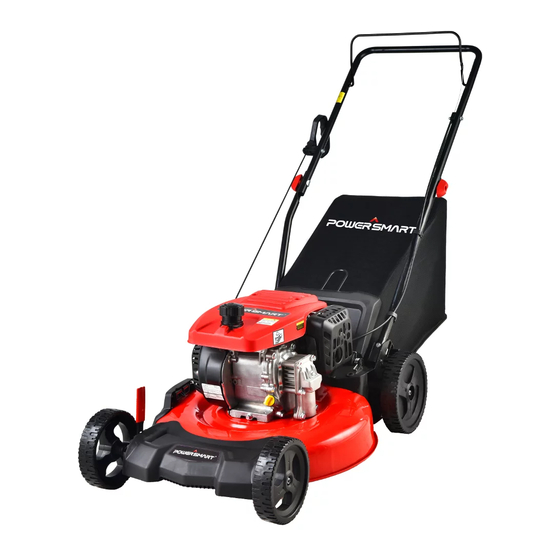
EN 21" 3-in-1 GAS PUSH LAWN MOWER
FR 21" 3-in-1 TONDEUSE A GAZON A PROPULSION DE GAZ
ES 21" 3-en-1 CORTADORA DE CÉSPED A GASOLINA
Model # DB2194PH
Have product questions or need technical support? Please feel free to contact us!
Toll free: 1-800-791-9458Mon-Fri9-5 EST
Email: support@amerisuninc.com
Advertisement
Table of Contents

Related Manuals for Powersmart DB2194PH


Summary of Contents for Powersmart DB2194PH
- Page 1 EN 21" 3-in-1 GAS PUSH LAWN MOWER FR 21" 3-in-1 TONDEUSE A GAZON A PROPULSION DE GAZ ES 21" 3-en-1 CORTADORA DE CÉSPED A GASOLINA Model # DB2194PH Have product questions or need technical support? Please feel free to contact us! Toll free: 1-800-791-9458Mon-Fri9-5 EST...
-
Page 3: Table Of Contents
Operation……………………..………………………………………… 13 Maintenance……………………………………………………………... Storage……………………………………………………………………. 19 Troubleshooting…………………………………………………………. Exploded view & parts list……………………………………………… Warranty………………………………………………………………… TECHNICAL DATA 21" 3-in-1 Gas Push Lawn Mower Model # DB2194PH Engine type: 4 Stroke, OHV, single cylinder with forced air-cooling system Displacement: 209cc Fuel tank capacity: 0.24 Gallon Oil capacity: 16.9 fl.oz... -
Page 4: Introduction
INTRODUCTION Thank You for Purchasing a PowerSmart ® Product. This manual provides information regarding the safe operation and maintenance of this product. Every effort has been made to ensure the accuracy of the information in this manual. PowerSmart ® reserves the right to change this product and specifications at any time without prior notice. -
Page 5: General Safety Procedures
GENERAL SAFETY PROCEDURES For any questions regarding the hazard and safety notices listed in this manual or on the product, please call (800) 791-9458 Mon-Fri 9-5 EST before using the engine. DANGER: CARBON MONOXIDE Using an engine indoors CAN KILL YOU IN MINUTES. Engine exhaust contains carbon monoxide (CO). -
Page 6: Important Safety Instructions
IMPORTANT SAFETY INSTRUCTIONS This machine is capable of amputating hands and feet and throwing objects. Failure to observe the following safety instructions could result in serious injury or death. I.General Operation 1. Read, understand, and follow instructions and warnings in this manual and on the machine, engine and attachments. - Page 7 4. Always keep the machine in gear when going down slopes. Do not coast downhill. 5. Avoid starting and stopping on slopes. Avoid making sudden changes in speed or direction. Make turns slowly and gradually. 6. Use extra care while operating machine with a grass catcher or other attachment(s). They can affect the stability of the machine.
-
Page 8: Warning Label Instructions
WARNING LABLE INSTRUCTIONS Read carefully the manual before use. Danger-flying objects; keep safe distance from the machine as long as the engine is running. Do not open or remove safety shields while engine is running. Pay more attention to the operator’s hands and feet to avoid injury. Do not open or remove safety shields while engine is running. - Page 9 Look behind while backing Steep slope hazard When repairing, please pull off the spark plug boot, then repair it according to the operational manual Hot surfaces When mowing,please wear the glasses ad ear plugs to defend the operator himself Keep bystanders away. Safety label found on the lawn mower: KEEP HANDS AND FEET AWAY.
-
Page 10: Knowing Your Lawn Mower
KNOWING YOUR LAWN MOWER Please use the illustration below to familiarize yourself with the location and function of the components that control of your lawn mower. Recoil starter handle Oil dipstick Grass catcher Fuel tank cap Cutting height adjustment lever Rear discharge door Rear wheel Lower handle... -
Page 11: Lawn Mower Preparation
LAWN MOWER PREPARATION The following section describes steps necessary to prepare the lawn mower for use. If after reading this section, you are unsure about how to perform any of the steps please call (800) 791-9458 Mon-Fri 9-5 EST for customer service. - Page 12 Cable Clip 4. Insert the recoil starter handle cable into the hook provided on the upper handle. You must engage the start/stop control to release the recoil starter handle. Start/Stop Control Recoil starter handle SIDE DISCHARGE CHUTE To convert mower for side discharge, the grass catcher has been removed and that the rear discharge door is closed.
-
Page 13: Operation
Warning! Cutting height adjustments should only be performed after the engine and blades have come to a complete stop! It is always best to begin cutting your lawn with a higher deck height to prevent scalping your lawn. The cutting height is adjusted with front and rear levers. Actuate the adjustment lever and pull it to the required position. - Page 14 Remove the fuel tank cap and check fuel level. If the level is too low, refuel the tank, remember adding fuel not over the fuel upper level. Warning: 1. Gasoline is extremely flammable and is explosive under certain conditions. 2. Refueling in a well-ventilation area with the engine stopped. Do not smoke and allow flames or sparks in the area where gasoline is stored or where the fuel tank is refueled.
- Page 15 Before you start mowing, you should run through this process several times in order to ensure that the lever and actuator cables are working properly. Repeat the test several times after the engine has started up. When the engine start/stop Control is released, the engine must stop within a few seconds. If not, contact Customer Service. Warning: The blade begins to rotate as soon as the engine is started.
-
Page 16: Maintenance
Caution: Do not remove side discharge cover at any time. USING AS A REAR BAGGER To use the grass catcher to collect clippings while you are operating the mower. 1. Attached grass catcher following instruction in the lawn mower preparation. Grass clippings will automatically collect in bag as you run the mower. - Page 17 Warning: Never tip the mower more than 90° in any direction and do not leave the mower tipped for any length of time. Oil can drain into the upper part of the engine causing a starting problem. MOWER BLADE To ensure safe operation, have all blade sharpening, balancing and mounting work carried out by an authorized service center.
- Page 18 5. If necessary, replace the paper element. 6. Reinstall the sponge-like element in the air cleaner casing and reinstall the cover. CAUTION: running the engine with dirty, damaged or missing air cleaner element will cause the engine to wear out prematurely. SPARK PLUG MAINTENANCE The spark plug is important for proper engine operation.
-
Page 19: Storage
STORAGE CAUTION: Never place any type of storage cover or tarp on the MOWER while it is still hot. If the MOWER is being stored for extended periods of time (30 days or more), drain fuel tank and carburetor bowl. When storing the mower for extended periods of time: 1. -
Page 20: Exploded View & Parts List
EXPLODED VIEW AND PARTS LIST Item Stock # Description Item Stock # Description 9999960902 Engine 303071037 21 inch Blade 303090094 Gear box seat 303181407 Blade connector 303100100 Bearing 203052967 Belt cover... - Page 21 303160961 Left hand bevel gear 303110049 Square Key 303020240 Bolt 303060169 Multi wedge pulley 303042005 Flat washer 302040092 Multi wedge belt Tensioning pulley 303160962 Right bevel gear 203100004 assembly 303071551 Paper pad 303160195A Small tensioning sleeve 303090095 Gear box cover 303181406 Small tensioning plate Small tensioning plate...
- Page 22 Item Stock# Description Item Stock# Description 303020444 Bolt M6X12 303020608 Bolt CRANKCASE COVER, 9020960902 Cylinder head assembly 9563960902 LEFT...
-
Page 23: Warranty
9142960901 Rocker arm shaft 303100072 6205 bearing 9230960902 ROCKER ARM 9198960101 Oil filler gauge 303020444 Bolt M6X12 9158960901 CAM SHAFT 9142960902 Rocker shaft baffle 9564960901 Piston ring assembly 303020620 Bolt M8x60 9129960901 Piston 9051960902 Muffler tail pipe 9015960901 Connecting rod assembly 303020444 Bolt M6X12 9122960901... - Page 24 To make a claim under this Limited Warranty, you must return the entire power tool product; transportation prepaid, to PowerSmart. The owner must include a legible copy of the original receipt, which shall list the date of purchase, along with the company’s name where the product was purchased.
Need help?
Do you have a question about the DB2194PH and is the answer not in the manual?
Questions and answers
I lost the screw that goes in the handle down by the wheel. What screw is it, so I can buy a replacement. Thanks
The replacement screw for the Powersmart DB2194PH handle near the wheel is likely the Screw ST4.2*14, part number 303010095.
This answer is automatically generated