Advertisement
Quick Links
9257196COMUK
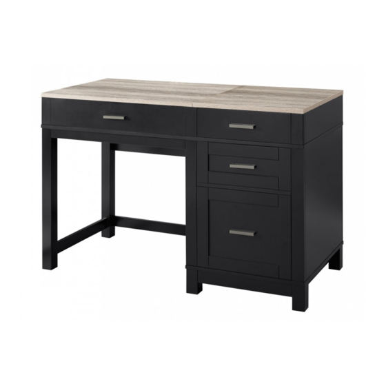
LIFT TOP DESK
Date of Purchase: ____/____/_____
Lot Number:
THIS INSTRUCTION BOOKLET CONTAINS IMPORTANT SAFETY INFORMATION. PLEASE READ AND KEEP FOR FUTURE REFERENCE.
Do Not Return This Product!
Contact our customer service team for help fi rst
Call: 01942 524100
email: cseurope@dorel.com
WARNING
–Unit can ! p over causing severe injury or death.
–Anchor unit to stud in wall (if instructed to)
–Do not allow children climb on unit
–Put heavy items on lower shelves or drawers
B349257196COMUK01
Easy
Assembly Diffi culty Meter
Tough
Advertisement

Related Manuals for Dorel 9257196COMUK


Summary of Contents for Dorel 9257196COMUK
- Page 1 9257196COMUK LIFT TOP DESK B349257196COMUK01 Date of Purchase: ____/____/_____ Lot Number: THIS INSTRUCTION BOOKLET CONTAINS IMPORTANT SAFETY INFORMATION. PLEASE READ AND KEEP FOR FUTURE REFERENCE. Do Not Return This Product! Contact our customer service team for help fi rst Call: 01942 524100 email: cseurope@dorel.com...
-
Page 2: Helpful Hints
Do NOT return this product! Contact our friendly customer service team fi rst for help Call us! 01942 524100 cseurope@dorel.com Helpful Hints PEOPLE NEEDED FOR ASSEMBLY: 1-2 ESTIMATED ASSEMBLY TIME: 1 HOUR - Open your item in the area you plan to keep it for less heavy li! ing - Iden"... -
Page 3: Before You Start
Before You Start Read through each step carefully and follow the proper order Separate and count all your parts and hardware Give yourself enough room for the assembly process Have the following tools: Flat Head Screwdriver, #2 Phillips Head Screwdriver and Hammer Cau! on: If using a power drill or power screwdriver for screwing, please be aware to slow down and stop when screw is ! ght. - Page 4 Board Iden• fi ca• on Not actual size T9257096010UD T9257096020UD T9257096030UD LIFT TOP PANEL RIGHT TOP PANEL LEFT SIDE PANEL T9257096040UD T9257096050UD T9257096060UD MIDDLE PARTITION SIDE SUPPORT PANEL RIGHT SIDE PANEL T9257096070UD T9257096080UD T9257096090UD RIGHT FRONT APRON UPPER BACK PANEL FRONT PANEL T9257096100UD T9257096110UD...
- Page 5 Board Iden• fi ca• on Not actual size T9257096130UD T9257096140UD T9257096150UD LEFT BACK PANEL BACK PANEL SUPPORT MIDDLE FRAME T9257096160UD T9257096170UD T9257096180UD RIGHT FRAME MIDDLE RAIL RIGHT BACK PANEL T9257096190UD T9257096200UD T9257096210UD LOWER SUPPORT PANEL LOWER SUPPORT PANEL LOWER SHELF T9257096220UD T9257096230UD T9257096240UD...
- Page 6 Board Iden• fi ca• on Not actual size T9257096250UD T9257096260UD T9257096270UD LEFT SUPPORT PANEL RIGHT SUPPORT PANEL SUPPORT WOOD BLOCK T9257096280UD T9257096290UD T9257096300UD UPPER DRAWER FRONT UPPER DRAWER LEFT UPPER DRAWER RIGHT T9257096310UD T9257096320UD T9257096330UD DRAWER BOTTOM MIDDLE DRAWER FRONT UPPER DRAWER BACK T9257096340UD T9257096350UD...
- Page 7 Board Iden• fi ca• on Not actual size T9257096370UD T9257096380UD T9257096390UD LOWER DRAWER FRONT LOWER DRAWER LEFT LOWER DRAWER RIGHT T9257096400UD T9257096410UD T9257096420UD LOWER DRAWER BACK LOWER DRAWER BOTTOM LIFT MECHANISM T9257096430UD T9257096440UD T9257096450UD SUPPORT TUBE SUPPORT TUBE LIFT MECHANISM...
-
Page 8: Part List
Hardware Bag Reference Number: 29257096COM0UD Part List Actual Size TUD0001 TUD0002 TUD0030 TUD0009 Cam Bolt Cam Lock DOWEL 6 X 30 CBS 4 x 38 15-12 TUD0008 TUD0007 TUD0011 TUD0022 CBS 4 X 30 CBS 3.5 x 16 CBS 3.5 x 12 PH M4 X 12... - Page 9 Hardware Bag Reference Number: 29257096COM0UD Part List Not Actual Size TUD0047 TUD0052 TUD0048 TUD0026 JCBC SCREW JCBC SCREW BARREL NUT ALLEN KEY 6 X 40 6 X 30 1/4” X 12 x1 SET TUD0049 TUD0050 TUD0012 FULL EXT. SLIDE METAL FILE HOLDER HANDLE 350 MM Ø5 X 356...
- Page 10 Step 1 * raw edges are shaded...
- Page 11 Step 2 TUD0001 TUD0002 TUD0030 TUD0009 * raw edges are shaded...
- Page 12 Step 3 x1 SET TUD0001 TUD0016 TUD0008 x1 SET TUD0049 TUD0049 (Cabinet member) * raw edges are shaded...
- Page 13 Step 4 Quick Assembly Proper orientation of CAM LOCK TUD0002 TUD0030 * raw edges are shaded...
- Page 14 Step 5 TUD0030 TUD0009 * raw edges are shaded...
- Page 15 Step 6 TUD0001 * raw edges are shaded...
- Page 16 Step 7 Quick Assembly Proper orientation of CAM LOCK TUD0002 TUD0030 * raw edges are shaded...
- Page 17 Step 8 TUD0001 TUD0012 TUD0011 * raw edges are shaded...
- Page 18 Step 9 Quick Assembly Proper orientation of CAM LOCK TUD0002 Note : Hole Boring Bo! om * raw edges are shaded...
- Page 19 Step 10 TUD0001 TUD0030 TUD0009 * raw edges are shaded...
- Page 20 Step 11 Quick Assembly Proper orientation of CAM LOCK TUD0002 TUD0030 * raw edges are shaded...
- Page 21 Step 12 TUD0026 x1 SET TUD0016 TUD0009 TUD0047 TUD0008 * raw edges are shaded...
- Page 22 Step 13 Quick Assembly Proper orientation of CAM LOCK TUD0001 TUD0022 TUD0030 TUD0002 * raw edges are shaded...
- Page 23 Step 14 TUD0052 TUD0053 TUD0054 TUD0026 TUD0041 TUD0053 TUD0054 TUD0041 TUD0026 * raw edges are shaded...
- Page 24 Step 15 TUD0008 Right Note: Facing front * raw edges are shaded...
- Page 25 Step 16 TUD0047 TUD0048 TUD0026 * raw edges are shaded...
- Page 26 Step 17 TUD0001 * raw edges are shaded...
- Page 27 Step 18 Quick Assembly Proper orientation of CAM LOCK TUD0002 30 / 35 29 / 34 * raw edges are shaded...
- Page 28 Step 19 Quick Assembly Proper orientation of CAM LOCK * raw edges are shaded...
- Page 29 Step 20 * raw edges are shaded...
- Page 30 Step 21 TUD0009 * raw edges are shaded...
- Page 31 Step 22 x1 SET TUD0016 TUD0008 * raw edges are shaded...
- Page 32 Step 23 Quick Assembly Proper orientation of CAM LOCK * raw edges are shaded...
- Page 33 Step 24 * raw edges are shaded...
- Page 34 Step 25 TUD0009 * raw edges are shaded...
- Page 35 Step 26 x1 SET TUD0016 TUD0008 * raw edges are shaded...
- Page 36 Step 27 x1 SET TUD0002 TUD0007 TUD0049 TUD0049 (Drawer member) * raw edges are shaded...
- Page 37 Step 28 Quick Assembly Proper orientation of CAM LOCK * raw edges are shaded...
- Page 38 Step 29 TUD0009 TUD0050 TUD0050 * raw edges are shaded...
- Page 39 Step 30 TUD0012 TUD0011 * raw edges are shaded...
- Page 40 Step 31 * raw edges are shaded...
- Page 41 Step 32 * raw edges are shaded...
- Page 42 Step 33 TUD0050 * raw edges are shaded...
-
Page 43: Maximum Loads
Maximum Loads This unit has been designed to support the maximum loads shown. Exceeding these load limits could cause sagging, instability, product collapse, and/or serious injury. Warning: Please make sure that all the objects are removed before moving the assembled unit. The unit must be li! ed by more than one person, not dragged or pushed.
Need help?
Do you have a question about the 9257196COMUK and is the answer not in the manual?
Questions and answers