Advertisement
Quick Links
Date of Purchase: ____/____/_____
Lot Number:
THIS INSTRUCTION BOOKLET CONTAINS IMPORTANT SAFETY INFORMATION. PLEASE READ AND KEEP FOR FUTURE REFERENCE.
Do Not Return This Product!
Contact our customer service team for help fi rst
WARNING
–Unit can ! p over causing severe injury or death.
–Anchor unit to stud in wall (if instructed to)
–Do not allow children climb on unit
–Put heavy items on lower shelves or drawers
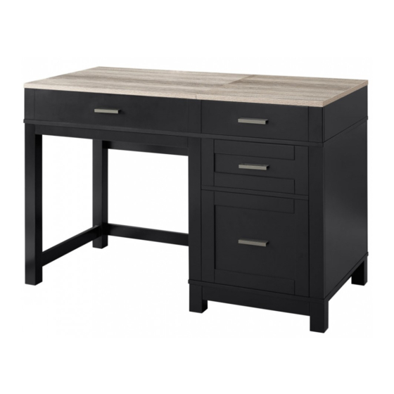
LIFT TOP DESK
Easy
Assembly Diffi culty Meter
Tough
Advertisement

Related Manuals for Dorel 9257196COM


Summary of Contents for Dorel 9257196COM
- Page 1 LIFT TOP DESK Date of Purchase: ____/____/_____ Lot Number: THIS INSTRUCTION BOOKLET CONTAINS IMPORTANT SAFETY INFORMATION. PLEASE READ AND KEEP FOR FUTURE REFERENCE. Do Not Return This Product! Contact our customer service team for help fi rst WARNING Easy Tough Assembly Diffi...
-
Page 2: Helpful Hints
Contact Us! Do NOT return this product! Contact our friendly customer service team fi rst for help Call us! Assembly Tips Helpful Hints PEOPLE NEEDED FOR ASSEMBLY: 1-2 ESTIMATED ASSEMBLY TIME: 1 HOUR - Open your item in the area you plan to keep it for less heavy li! ing - Iden"... - Page 3 BCfoCC You StCCt Read through each step carefully and follow the proper order Separate and count all your parts and hardware Give yourself enough room for the assembly process Have the following tools: Flat Head Screwdriver, #2 Phillips Head Screwdriver and Hammer Caution: If using a power drill or power screwdriver for screwing, please be aware to slow down and stop when screw is tight.
- Page 4 Board Iden• fi ca• on Not actual size LIFT TOP PANEL RIGHT TOP PANEL LEFT SIDE PANEL MIDDLE PARTITION SIDE SUPPORT PANEL RIGHT SIDE PANEL FRONT PANEL RIGHT FRONT APRON UPPER BACK PANEL UPPER SHELF LEFT FRAME LEFT FRONT APRON...
- Page 5 Board Iden• fi ca• on Not actual size LEFT BACK PANEL MIDDLE FRAME BACK PANEL SUPPOR RIGHT FRAME MIDDLE RAIL RIGHT BACK PANEL LOWER SHELF LOWER SUPPORT PANEL LOWER SUPPORT PANEL FOOT FOOT FOOT...
- Page 6 Board Iden• fi ca• on Not actual size SUPPORT WOOD BLOCK LEFT SUPPORT PANEL RIGHT SUPPORT PANEL UPPER DRAWER FRONT UPPER DRAWER LEFT UPPER DRAWER RIGHT UPPER DRAWER BACK DRAWER BOTTOM MIDDLE DRAWER FRONT MIDDLE DRAWER LEFT MIDDLE DRAWER RIGHT MIDDLE DRAWER BACK...
-
Page 7: Lift Mechanism
Board Iden• fi ca• on Not actual size LOWER DRAWER LEFT LOWER DRAWER RIGHT LOWER DRAWER FRONT LOWER DRAWER BACK LOWER DRAWER BOTTOM LIFT MECHANISM LIFT MECHANISM SUPPORT TUBE SUPPORT TUBE... -
Page 8: Part List
Part List Actual Size TUD0001 TUD0002 TUD0030 TUD0009 Cam Bolt Cam Lock DOWEL 6 X 30 CBS 4 x 38 15-12 TUD0008 TUD0007 TUD0011 TUD0022 CBS 4 X 30 CBS 3.5 x 16 CBS 3.5 x 12 PH M4 X 12... - Page 9 Part List Not Actual Size TUD0047 TUD0052 TUD0048 TUD0026 JCBC SCREW JCBC SCREW BARREL NUT ALLEN KEY 6 X 40 6 X 30 1/4” X 12 x1 SET TUD0049 TUD0050 TUD0012 FULL EXT. SLIDE METAL FILE HOLDER HANDLE 350 MM Ø5 X 356 x2 SETS TUD0041...
- Page 10 Step 1 * raw edges are shaded...
- Page 11 Step 2 TUD0001 TUD0002 TUD0030 TUD0009 * raw edges are shaded...
- Page 12 Step 3 x1 SET TUD0001 TUD0016 TUD0008 x1 SET TUD0049 TUD0049 (Cabinet member) * raw edges are shaded...
- Page 13 Step 4 TUD0002 TUD0030 * raw edges are shaded...
- Page 14 Step 5 TUD0030 TUD0009 * raw edges are shaded...
- Page 15 Step 6 TUD0001 * raw edges are shaded...
- Page 16 Step 7 Quick Assembly Proper orientation of CAM LOCK TUD0002 TUD0030 * raw edges are shaded...
- Page 17 Step 8 TUD0001 TUD0012 TUD0011 * raw edges are shaded...
- Page 18 Step 9 Quick Assembly Proper orientation of CAM LOCK TUD0002 Note : Hole Boring Bo! om * raw edges are shaded...
- Page 19 Step 10 TUD0001 TUD0030 TUD0009 * raw edges are shaded...
- Page 20 Step 11 Quick Assembly Proper orientation of CAM LOCK TUD0002 TUD0030 * raw edges are shaded...
- Page 21 Step 12 TUD0026 x1 SET TUD0016 TUD0009 TUD0047 TUD0008 * raw edges are shaded...
- Page 22 Step 13 Quick Assembly Proper orientation of CAM LOCK TUD0001 TUD0022 TUD0030 TUD0002 * raw edges are shaded...
- Page 23 Step 14 TUD0052 TUD0053 TUD0054 TUD0026 TUD0041 TUD0053 TUD0054 TUD0041 TUD0026 * raw edges are shaded...
- Page 24 Step 15 TUD0008 Right Note: Facing front * raw edges are shaded...
- Page 25 Step 16 TUD0047 TUD0048 TUD0026 * raw edges are shaded...
- Page 26 Step 17 TUD0001 * raw edges are shaded...
- Page 27 Step 18 Quick Assembly TUD0002 Proper orientation of CAM LOCK 30 / 35 29 / 34 * raw edges are shaded...
- Page 28 Step 19 Quick Assembly Proper orientation of CAM LOCK * raw edges are shaded...
- Page 29 Step 20 * raw edges are shaded...
- Page 30 Step 21 TUD0009 * raw edges are shaded...
- Page 31 Step 22 x1 SET TUD0016 TUD0008 * raw edges are shaded...
- Page 32 Step 23 Quick Assembly Proper orientation of CAM LOCK * raw edges are shaded...
- Page 33 Step 24 * raw edges are shaded...
- Page 34 Step 25 TUD0009 * raw edges are shaded...
- Page 35 Step 26 x1 SET TUD0016 TUD0008 * raw edges are shaded...
- Page 36 Step 27 x1 SET TUD0002 TUD0007 TUD0049 TUD0049 (Drawer member) * raw edges are shaded...
- Page 37 Step 28 * raw edges are shaded...
- Page 38 Step 29 TUD0009 TUD0050 TUD0050 * raw edges are shaded...
- Page 39 Step 30 TUD0012 TUD0011 * raw edges are shaded...
- Page 40 Step 31 * raw edges are shaded...
- Page 41 Step 32 * raw edges are shaded...
- Page 42 Step 33 TUD0050 * raw edges are shaded...
-
Page 43: Maximum Loads
Maximum Loads This unit has been designed to support the maximum loads shown. Exceeding these load limits could cause sagging, instability, product collapse, and/or serious injury. Warning: Please make sure that all the objects are removed before moving the assembled unit. The unit must be li! ed by more than one person, not dragged or pushed. - Page 44 Register your product to receive the following: * New trend details -sneak peek on what's new * Surveys -have a voice within our community * Exclusive deals and discount codes * Quick and easy replacement part service Visit your local retailer's website, rate your purchased product and leave us some feedback! We would like to extend a big "Thank You"...
- Page 45 Español Cubierta Delantera Este libro de instrucciones con! ene información IMPORTANTE de seguridad. Por favor lea y manténgalo para referencia en el futuro. No Regrese este producto! Comuniquese con nuestro amistoso equipo de servicio al cliente para obtener ayuda. PRECAUCION Este mueble puede volcarse y causar graves heridas y/o muerte.
- Page 46 Español Página 10 Cómo SEPARAR PELOTA DE COJINETE DE BOLAS. 1) Tire hacia la fl echa para abrir la corredera hasta que se detenga y luego gírela. 2) Empuje la palanca de plás" co hacia abajo y sepárela. Miembro del gabinete Miembro de cajon Página 12 Miembro del gabinete...
- Page 47 Español Página 43 ETIQUETA DE PRECAUCIÓN CARGA MAXIMA Esta unidad ha sido diseñada para soportar la carga máxima anotada. El exceder estos límites puede causar inestabilidad, colapsarse y/o causar serias lesiones. Advertencia: asegúrese de quitar todos los objetos antes de mover la unidad ensamblada. La unidad debe ser levantada por más de una persona, no arrastrada o empujada.
- Page 48 Français capot avant Ce livret d’instruc! ons con! ent d’importantes informa! ons de sécurité. S’il vous plaît lire et conserver pour référence ultérieure. Ne pas retourner ce produit! Contactez notre équipe de service à la clientèle amical pour aider. MISE EN GARDE Ce mobilier peut basculer et causer des blessures graves et / ou la mort.
- Page 49 Français page 10 Comment faire pour séparer la glissière de roulement à billes. 1) Tirez vers la fl èche pour ouvrir la glissière jusqu’à sa butée, puis retournez-la. 2) Abaissez le levier en plas" que et séparez-le. Membre du cabinet Membre "...
- Page 50 Français Page 43 MISE EN GARDE MAXIMUM DE CHARGE Cet appareil est conçu pour supporter la charge maximale enregistrée. Le dépassement de ces limites peut provoquer l’instabilité, l’eff ondrement et / ou causer des blessures graves. Aver" ssement: Veuillez vous assurer que tous les objets sont re" rés avant de déplacer l’unité assemblée. L’unité doit être soulevée par plus d’une personne, non traînée ou poussée.
Need help?
Do you have a question about the 9257196COM and is the answer not in the manual?
Questions and answers