Table of Contents
Advertisement
Quick Links
Instruction manual SMART PRO
models:
ST 1, ST 2, ST 3, ST 4, ST 5, ST 6,
ST 500, ST 700, ST 1200, ST 1450,
ST 500 M, ST 700 M, ST 1200 M, ST 1450 M
Laboratory refrigerators
models:
CHL 1, CHL 2, CHL 3, CHL 4, CHL 5, CHL 6,
CHL 500, CHL 700, CHL 1200, CHL 1450
CHL 500 M, CHL 700 M, CHL 1200 M, CHL 1450 M
models:
ST 1/1, ST 1/1/1, ST 2/2, ST 2/3
CHL 1/1, CHL 1/1/1, CHL 2/2, CHL 2/3
ST1/CHL1, ST2/CHL2, ST2/CHL3
models:
ILW 53, ILW 115, ILW 240, ILW 400, ILW 750
Before using the equipment, please read carefully this instruction manual!
1
Thermostatic cabinets
Multichamber devices
Laboratory incubators
Version 1.30
Issued 12.05.2022
Advertisement
Table of Contents

Related Manuals for POL-EKO SMART PRO ST 1


Summary of Contents for POL-EKO SMART PRO ST 1
- Page 1 Instruction manual SMART PRO Thermostatic cabinets models: ST 1, ST 2, ST 3, ST 4, ST 5, ST 6, ST 500, ST 700, ST 1200, ST 1450, ST 500 M, ST 700 M, ST 1200 M, ST 1450 M Laboratory refrigerators models: CHL 1, CHL 2, CHL 3, CHL 4, CHL 5, CHL 6, CHL 500, CHL 700, CHL 1200, CHL 1450...
- Page 2 Instruction manual ST, CHL, ILW SMART PRO Manufacturer's address: POL-EKO-APARATURA sp. j. ul. Kokoszycka 172 C 44-300 Wodzisław Śląski Country of origin: Polska As a manufacturer, we inform you that we took the necessary measures to ensure that this device fully meets your expectations and is reliable for a long period of use.
-
Page 3: Table Of Contents
Instruction manual ST, CHL, ILW SMART PRO Contents: INTENDED USE AND IMPORTANT INFORMATION FOR THE USER ............6 PACKAGE CONTENTS ..........................7 BEFORE THE FIRST USE ..........................8 3.1. Installation of shelves ........................... 10 3.2. Condensation in the chamber ....................... 13 3.3. - Page 4 Instruction manual ST, CHL, ILW SMART PRO 6.7.4. Summary of segments........................42 6.7.5. Protection class ..........................43 6.7.6. Temperature protection ........................43 6.7.7. Priority .............................. 44 6.7.8. Loop ..............................44 6.7.9. Defrosting program (only for CHL 1-6, CHL 500, CHL 700, CHL 1200, CHL 1450) .....
- Page 5 Instruction manual ST, CHL, ILW SMART PRO INTERFACE ..............................81 7.1. MODBUS TCP ............................81 TEMPERATURE PROTECTION ........................81 8.1. Temperature protection class ....................... 81 CONNECTING THE DEVICE TO A COMPUTER ..................82 10. OPERATION OF THE COOLING SYSTEM ....................82 11.
-
Page 6: Intended Use And Important Information For The User
Instruction manual ST, CHL, ILW SMART PRO 1. INTENDED USE AND IMPORTANT INFORMATION FOR THE USER ST thermostatic cabinets, CHL refrigerators and ILW cooled incubators are laboratory devices designed for incubation and storage of samples at following temperature ranges: • thermostatic cabinets ST: +3°C …... -
Page 7: Package Contents
Instruction manual ST, CHL, ILW SMART PRO • disconnect the unit from the mains before undertaking any repairs or maintenance work (in order to not lose the warranty during its duration, all repairs should be carried out by an authorized service), •... -
Page 8: Before The First Use
Instruction manual ST, CHL, ILW SMART PRO 3. BEFORE THE FIRST USE The manufacturer sends the device protected by cardboard profiles and foil. The device should be transported in an upright position and the package should be secured against sliding during transport. After receiving the device, visually assess its condition and equipment in the presence of the person delivering the goods. - Page 9 Instruction manual ST, CHL, ILW SMART PRO Wheels / leveling feet The device has been equipped with wheels or leveling feet. After placing the unit at its destination, secure the device against movement by locking the wheels. In the case of feet, after placing the device in the destination, they should be leveled.
-
Page 10: Installation Of Shelves
Instruction manual ST, CHL, ILW SMART PRO 3.1. Installation of shelves In the ST 1-6, CHL 1-6 models To install the shelf or to change its position, follow these steps: Install the shelf slide at the selected height by inserting it into proper slots on the wall of the device. Do the same with the slide on the opposite wall. - Page 11 Instruction manual ST, CHL, ILW SMART PRO In the ST 500 - 1450, ST 500 M - 1450 M, CHL 500 – 1450, CHL 500 M - 1450 M models To install the shelf or to change its position, follow these steps: Install the shelf slide at the selected height by inserting it into proper slots on the wall of the device.
- Page 12 Instruction manual ST, CHL, ILW SMART PRO In the ILW models To install the shelf or to change its position, follow these steps: Install the shelf slide at the selected height by inserting it into perforations on the wall of the device. Do the same with the slide on the opposite wall.
-
Page 13: Condensation In The Chamber
Instruction manual ST, CHL, ILW SMART PRO 3.2. Condensation in the chamber If the set temperature is much lower than the ambient temperature, condensation may occur, which will cause accumulation of the water at the bottom of the chamber. The amount of accumulated water depends on the following factors: •... -
Page 14: Anchoring Of The Equipment
Instruction manual ST, CHL, ILW SMART PRO 3.5. Anchoring of the equipment In the case of high equipment (ST 500, ST 500 M, CHL 500, CHL 500 M, ST 700, ST 700 M, CHL 700, CHL 700 M, ST 1200, ST 1200 M, CHL 1200, CHL 1200 M, ST 1450, ST 1450 M, CHL 1450, CHL 1450 M) and multi-chamber units they must be anchored to the wall with suitable fixings (the anchoring kit is supplied with the device). -
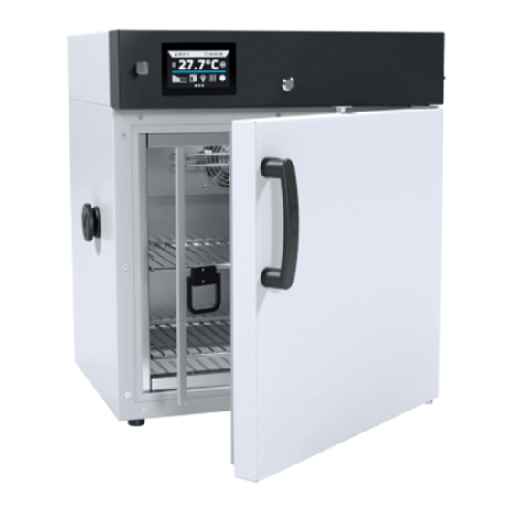
Page 15: Description Of The Device
Instruction manual ST, CHL, ILW SMART PRO 4. DESCRIPTION OF THE DEVICE SMART PRO models are equipped with a PID microprocessor temperature controller and a 7 inch colour touch screen with a resolution of 800x480. 4.1. Design of ST / CHL devices Below there’s a picture of ST model (exemplary photo) with a description of the important components of the device. - Page 16 Instruction manual ST, CHL, ILW SMART PRO Rear view main switch condenser cooling system fuse main power socket C14 LAN port...
- Page 17 Instruction manual ST, CHL, ILW SMART PRO Rear view (ST/CHL 500 M - 1450 M models) anchoring handle integrated power cable fuse main switch LAN port...
-
Page 18: Design Of Ilw Devices
Instruction manual ST, CHL, ILW SMART PRO 4.2. Design of ILW devices Below there’s a picture of ILW 115 model (exemplary photo) with a description of the important components of the device. Front view rating plate access port ø30mm for external sensor internal glass door shelf... - Page 19 Instruction manual ST, CHL, ILW SMART PRO Rear view main switch adjustable feet LAN port fuse main power socket C20...
-
Page 20: Device Equipment (Standard And Optional)
Instruction manual ST, CHL, ILW SMART PRO 5. DEVICE EQUIPMENT (STANDARD AND OPTIONAL) 5.1. Internal glass door (optionally for ST / CHL, standard for ILW) Internal glass door is an optional equipment in ST thermostatic cabinets and CHL laboratory refrigerators. For ILW cooled incubators it’s a standard equipment. To open and close the door use the plastic handle attached to the glass. -
Page 21: Internal Socket (Optionally For St, Chl, Ilw)
Instruction manual ST, CHL, ILW SMART PRO During operation, when the temperature inside the chamber is high, do not touch the internal components and glass doors, as there is a risk of burns. Use protective gloves to protect yourself against the effects of burns from hot components. 5.4. -
Page 22: Open Door Alarm (Standard For St, Chl, Ilw)
Instruction manual ST, CHL, ILW SMART PRO 5.7. Open door alarm (standard for ST, CHL, ILW) All units have been equipped with an open door sensor. If you open the door, the icon: will appear (the number above the icon presents open door counter. Press the icon to cancel the counter. The counter is also cancelled by turning of the device). -
Page 23: Phytotron Fit (Optionally For St And Ilw)
Instruction manual ST, CHL, ILW SMART PRO After copying the data to the USB flash drive, before removing it from the USB socket, it should be unmoun- ted by pressing the icon in the top drop-down list (Figure 1). If the pendrive is not unmounted after connecting to the computer, a message about pendrive damage may be displayed with a repair proposal, when actually the pendrive is not damaged Figure 1 Unmounting USB flash drive... -
Page 24: Display Battery Backup (Optionally For St, Chl, Ilw)
Instruction manual ST, CHL, ILW SMART PRO Figure 2 Main screen for devices with phytotron If a phytotron is not switched on, the icon is inactive. To program a phytotron, see the Section 6.7.3. 5.11. Display battery backup (optionally for ST, CHL, ILW) Units in the SMART PRO version can be optionally equipped with a battery backup of the display. -
Page 25: Device Operation
Instruction manual ST, CHL, ILW SMART PRO 6. DEVICE OPERATION This symbol means that a given window can be moved in the direction shown in the picture. 6.1. External memory (USB flash drive) The external memory (USB flash drive) allows to copy: instruction manual, data record, event log and service log from the device memory. -
Page 26: User Logging In
Instruction manual ST, CHL, ILW SMART PRO Figure 5 Keypad Deleting the entire text Changing to capital letters (it´s matters when entering login and password). Changing to numbers and special characters. Changing to letters. Deleting the entered character. Confirming the entered text / closing the keypad. Sometimes entered characters can be hidden (then they are replaced with „* ”). -
Page 27: Main Screen
Instruction manual ST, CHL, ILW SMART PRO Logging out: press in the main menu. For automatic logout, go to the Section 6.16. 6.5. Main screen After turning on the device, the main screen (Figure 7) appears. It contains the information about the device status. After starting the program, additional information appears on the screen (Figure Figure 7 Main screen (program is switched off, no user is logged in) -
Page 28: Information Panel
Instruction manual ST, CHL, ILW SMART PRO 6.5.1. Information panel There are four different windows in the information panel. Switching between them is done by swiping the finger left or right. Figure 9 Information panel The icon indicates information about which window is active. 6.5.1.1. - Page 29 Instruction manual ST, CHL, ILW SMART PRO Figure 11 Alarm details With more alarms, a button appears on the right side of the list and allows you to enlarge the view to full screen. 6.5.1.2. Status panel The status of the device is displayed descriptively on the third page of the information panel (Figure 12).
-
Page 30: The Meaning Of Icons And Symbols
Instruction manual ST, CHL, ILW SMART PRO Figure 13 Status – protection and alarms 6.5.2. The meaning of icons and symbols The icon allows you to go to the main screen. Automatic return to the home screen. Factory setting: disabled. The icon allows you to go to the main menu. - Page 31 Instruction manual ST, CHL, ILW SMART PRO Schedule activated - the program will run from-to the given date / time Icon is visible only when the chamber is cooling down. Icon is visible only when the chamber is heating up. Icon is visible only when the automatic defrosting function or defrosting program is running.
-
Page 32: Upper Expandable And Configurable Menu
Instruction manual ST, CHL, ILW SMART PRO Turning off of the alarm sound (open door alarm, exceeding temperature range). Critical alarms (i.e. damage to the temperature sensor, temperature protection, etc.) continue emitting a sound. When the program is running, click the icon to quickly change the fan speed in ST 1-6, CHL 1-6 and ILW (Quick Change function). -
Page 33: Quick Note - User's Message
Instruction manual ST, CHL, ILW SMART PRO Figure 15 Upper expandable menu when the program is stopped Positions available on the upper bar can be personalized. Just drag the selected icon to a new location (Figure 16). Figure 16 Changing icon’s position Quick Note –... -
Page 34: Alarm Bar
Instruction manual ST, CHL, ILW SMART PRO changed. Entered notes can be seen in the event log, they are symbolized by the icon . More information Section 6.13. Figure 17 User’s message 6.5.5. Alarm bar The Alrm Bar is a quick visual information about the device status. The colour of the bar indicates the status of the device: –... - Page 35 Instruction manual ST, CHL, ILW SMART PRO In order to go to Quick program, first you have to log in (if none of the users is logged in, the icon of Quick program will be inactive - grayed out). Then click the icon in the main screen.
-
Page 36: Programs
Instruction manual ST, CHL, ILW SMART PRO Figure 20 Quick program on programs list In Quick program editing mode, you can change: • settings of the data recording interval, • settings of the protection class. Temperature protection The highest protection class available for the device is set. The protection values depend on the set temperature: •... -
Page 37: Creating / Editing A Program
Instruction manual ST, CHL, ILW SMART PRO Figure 21 List of programs Information on the number of created programs / the maximum number of programs that the user can create is at the top of the screen (programs: 1/10). 6.7.1. Creating / editing a program Press the button and a panel with program parameters will appear (Figure... -
Page 38: Segments Edition
Instruction manual ST, CHL, ILW SMART PRO Cancels adding or editing of the program. Going to the edition of program segments. With more parameters, the window can be scrolled up and down. 6.7.2. Segments edition For each program, you can set maximum 100-segment time-temperature profiles that allow you to gradually increase or decrease the incubation temperature of the samples. - Page 39 Instruction manual ST, CHL, ILW SMART PRO The active value is highlighted in blue. The item highlighted in red means that the value is out of range and you should enter another one, e.g. the temperature is above / below the operating range of the device or the protection temperature.
-
Page 40: Phytotron Fit (Optionally For St And Ilw)
Instruction manual ST, CHL, ILW SMART PRO Figure 24 6.7.3. Phytotron FIT (optionally for ST and ILW)* * The phytotron option is not available for thermostatic cabinets with a monoblock, i.e. ST 500 M, ST 700 M, ST 1200 M and ST 1450 M. - Page 41 Instruction manual ST, CHL, ILW SMART PRO removed, select only those that will be used (Figure 26). For example, when the lighting panel will not be used and has been removed from the device, it must be turned off (uncheck the box next to the shelf number). When the illumination panel will be used and inserted into the device, turn it on (mark the box next to the shelf number).
-
Page 42: Summary Of Segments
Instruction manual ST, CHL, ILW SMART PRO 6.7.3.2. Equipment with few independently controlled illumination zones (optionally) The phytotron version with illumination panels can be equipped with an option (additionally paid) allowing independent control of each lighting panel. To set the light intensity in each panel separately: 1. -
Page 43: Protection Class
Instruction manual ST, CHL, ILW SMART PRO • fan efficiency (for ST 1-6, CHL 1-6, ILW). Figure 30 The summary of the segment Confirms and saves the changes Cancels the entered changes in the segments and goes to program parameters With more parameters, the window can be scrolled up and down. -
Page 44: Priority
Instruction manual ST, CHL, ILW SMART PRO bottom protection temperature: maximum +20°C upper protection temperature: minimum + 30°C 6.7.7. Priority Can be set in terms of: Parameters: In the program without ramp – the device starts the countdown of the segment time when the set temperature is reached. -
Page 45: Starting The Program
Instruction manual ST, CHL, ILW SMART PRO CHL laboratory refrigerators (without PLUS - automatic defrosting function) have a special defrosting program (Figure 32). It appears on the programs list available in the main screen after pressing the button . Defrosting is the temporary activation of heaters, which are intended to defrost a coating of ice or frost accumulated on the walls of the chamber during normal use. - Page 46 Instruction manual ST, CHL, ILW SMART PRO Figure 33 Main menu Figure 34 Program management menu If the program is running, the symbol appears next to the program name on the list. The symbol means that the program has been edited, but the changes have not been confirmed (Figure 35).
-
Page 47: The Second Way
Instruction manual ST, CHL, ILW SMART PRO 6.8.2. The second way • In the main screen press the icon in the upper right corner (Figure 36) • In the upper left corner press „PROGRAM” • Select the program you want to start (Figure 37). -
Page 48: Quick Change Of Parameters
Instruction manual ST, CHL, ILW SMART PRO 6.9. Quick change of parameters You cannot make a quick change (of time / temperature) in a running program that belongs to another user. Information about the program owner can be found in the information panel (lower left corner). Although the ramp time has been included in the program, the Quick Change of parameters will take place immediately while the temperature is being reached. -
Page 49: Quick Change Of Set Time
Instruction manual ST, CHL, ILW SMART PRO Figure 39 Quick change of set temperature 6.9.2. Quick change of set time In order to quickly change the duration time of a running program, press the icon in the main screen (Figure 40). Select the number of days, hours and minutes by scrolling the list up or down (Figure 41). -
Page 50: Quick Change Of Fan Efficiency (Only For Ilw, St 1-6, Chl 1-6)
Instruction manual ST, CHL, ILW SMART PRO Figure 41 Quick change of set time 6.9.3. Quick change of fan efficiency (only for ILW, ST 1-6, CHL 1-6) In order to quickly change the fan efficiency, press the icon in the main screen (Figure 42). -
Page 51: Schedules
Instruction manual ST, CHL, ILW SMART PRO Figure 43 Quick change of fan efficiency 6.10. Schedules The option allows creating a list of programs to be implemented in a given time. You can create several independent schedules. The schedules window contains a list of all created schedules of the logged-in user (Figure 44). -
Page 52: Creating / Editing A Schedule
Instruction manual ST, CHL, ILW SMART PRO Stop the schedule Add the schedule Edit the schedule Delete the schedule 6.10.1. Creating / editing a schedule To create / edit a schedule, press the button . The panel with schedule parameters will appear on the screen (Figure 45). - Page 53 Instruction manual ST, CHL, ILW SMART PRO Figure 46 Adding a program to the schedule Select a program from the drop-down list and press on the field next to the inscription "program" (Figure 47). Informa- tion about the selected program will be displayed (Figure 48): number of segments, number of cycles, priority, tempera- ture protection, upper protection, lower protection.
- Page 54 Instruction manual ST, CHL, ILW SMART PRO Figure 48 Information about the program Press the 'start date' field and then set the date and time of program start. Press the 'stop date' field and then set the date and time of the program end.
-
Page 55: Starting A Schedule
Instruction manual ST, CHL, ILW SMART PRO You can assign up to 10 programs to one schedule. In total you can create ten schedules. When creating a schedule, consider the following restrictions: • the start time of the first program on the list cannot be earlier than the current date and time, •... - Page 56 Instruction manual ST, CHL, ILW SMART PRO Figure 50 List of schedules Start the schedule 6.10.2.2. The second way • In the main screen press the icon (Figure 51), then press the SCHEDULE inscription. The schedule se- lection window will be displayed (Figure 52).
-
Page 57: Statistics
Instruction manual ST, CHL, ILW SMART PRO Figure 52 Selection of the schedule 6.11. Statistics Go to the main menu and press the icon . This panel (Figure 53) displays statistics of the currently running program or program that has ended Statistics are calculated separately for each segment. Data logging for calculation starts after 30 seconds from reaching the set temperature in the segment. -
Page 58: Data Record
Instruction manual ST, CHL, ILW SMART PRO Figure 53 Statistics 6.12. Data record Go to the main menu and press the icon . Data record window (Figure 54) contains the following information: • time and date of sample registration [date], •... -
Page 59: Graph
Instruction manual ST, CHL, ILW SMART PRO Press to continue downloading data Recording data onto the USB flash drive. .csv files are available - separated by semicolon when opening e.g. with a spreadsheet, .plkx - opening with the Lab Desk application Before removing the USB flash drive from the USB port, it must be unmounted, see Section 5.8. -
Page 60: Data Storage Directly On A Usb Flash Drive
Instruction manual ST, CHL, ILW SMART PRO Returns to displaying the entire chart (undo all magnifications) / returns to the list of charts. Returns to data register The opening time of the chart depends on the number of saved data samples. The greater the number of saved samples, the longer this window will open. -
Page 61: Event Log
Instruction manual ST, CHL, ILW SMART PRO • the current measurement is saved to a file named measurements.csv, • if the size of the current file exceeds 513 kB or the calendar month is changed, the current file is named in the format yyyy-mm_ measurements_0.csv, where 0 means the file number in the month, e.g. - Page 62 Instruction manual ST, CHL, ILW SMART PRO Figure 59 QR code The events in the event log are sorted chronologically. However, it may happen that the event "Program restarted" will not be displayed according to the chronology but the date and time of the event will be correct. This is not an error. Before removing the USB flash drive from the USB port, it must be unmounted, see Section 5.8.
- Page 63 Instruction manual ST, CHL, ILW SMART PRO Upper temp. alarm End over- temperature protection has been deactivated Date/time change date/time has been changed Lower temp. alarm Start activation of the alarm of exceeding the temperature below the set temperature Lower temp. alarm End deactivation of the alarm of exceeding the temperature below the set temperature Upper temp.
-
Page 64: Info
Instruction manual ST, CHL, ILW SMART PRO 6.14. Info Go to the main menu and press the icon . The panel contains the following information: • name of device, • temperature range of the device, • serial number of the device, •... -
Page 65: Users
Instruction manual ST, CHL, ILW SMART PRO Before removing the USB flash drive from the USB port, it must be unmounted, see Section 5.8. 6.15. Users Go to the main menu and press the icon . In this panel (Figure 63) you can add a new user, edit an existing one or delete it. -
Page 66: Account Types And Their Limits
Instruction manual ST, CHL, ILW SMART PRO • programs limit – number of programs that can be created by the user / number of available programs (it’s not possible to set a limit to the User). Figure 64 Editing a user Confirms and saves the user Cancels introduced changes and returns to the users list The device can have maximum 5 users. - Page 67 Instruction manual ST, CHL, ILW SMART PRO Temporarily silencing the alarms ✔ ✔ ✔ ✘ ✘ Enabling / disabling the sound ✔ Saving a Quick Note ✔ ✔ ✔ Creating users accounts ✔ ✘ ✘ Changing user's settings ✔ ✘ ✘...
-
Page 68: User Settings Panel
Instruction manual ST, CHL, ILW SMART PRO Figure 66 Menu available for Admin User account: • has access to programs menu , where User can start programs previously assigned to him, check their statistics (statistics, data register), check events history of the equipment (event log) and the information about the system (info), •... -
Page 69: Unlocking The Touch Screen
Instruction manual ST, CHL, ILW SMART PRO Change the name of the equipment – by default, the device serial number is entered. Change the language in the equipment´s menu. Set the time after which the screen will be dimmed. Turn on/off the sound . Critical alarms will continue emitting a sound. Set the time after which the user will be automatically logged out. -
Page 70: Time
Instruction manual ST, CHL, ILW SMART PRO Figure 69 Unlocking the touch screen 6.17. Time Go to the main menu and press the icon . In this panel you can change the date and system time and time zone. The time and time zone must be set correctly during the first start-up. Change of the date / system time If the date / system time is changed to the later date / time comparing with the data and events which are stored in the memory, they will remain in the register. -
Page 71: Alarms
Instruction manual ST, CHL, ILW SMART PRO • while enabling the automatic synchronization option and then every 12 hours ( • after starting the unit, then every 12 hours If the time in the equipment was set incorrectly or it became out of sync with the period of use (which is natural), then if: •... -
Page 72: Stm Function
Instruction manual ST, CHL, ILW SMART PRO In the field "lower alarm temp" you can set a value of -0,5°C to - 5°C and in the field "upper alarm temp" you can set a value of +0,5°C to +5°C. The lower and upper alarm can only be activated after reaching the set temperature. •... - Page 73 Instruction manual ST, CHL, ILW SMART PRO Figure 73 Option enabled, the program is stopped The function status is signaled with the following colors: • no STM on the display - option disabled, • white color - option enabled, the program is stopped, •...
-
Page 74: Mute Option
Instruction manual ST, CHL, ILW SMART PRO Figure 75 Option enabled, warning about problems with reaching / maintaining the temperature Possible causes: damaged heater, the sample inserted into the chamber absorbs / dissipates too much energy. If the color was red before opening the door, the color changes to blue after opening the door. In case of activation of the function (detection of problems with reaching / maintaining the temperature): •... - Page 75 Instruction manual ST, CHL, ILW SMART PRO • DHCP – you can select if the server that allocates IP addresses is running on the local network. You can then skip setting IP, Masks, Gates Icon indicates the connection status: Device connected to the network Device disconnected from the network Figure 76 LAN settings Confirms changes...
-
Page 76: E-Mail Reports
Instruction manual ST, CHL, ILW SMART PRO Confirms changes Cancels the entered changes 6.20. E-mail reports Go to the main menu and press the icon . In this window you can set the parameters needed to activate e- mail notifications. In the panel there are three windows: Selection of event types for which notifications should be sent (Figure 78). - Page 77 Instruction manual ST, CHL, ILW SMART PRO Figure 79 E-mail: Sender – Recipients Confirms changes Cancels the entered changes Configuration of the sender's e-mail account (Figure 80) In this window, enter your e-mail account details: • SMTP server user ID •...
-
Page 78: Automatic Defrosting Function (Optionally For St 1-6, St 500-1450, Chl 1-6, Chl 500-1450, Ilw, Standard For St 500 M-1450 M I Chl 500 M-1450 M)
Instruction manual ST, CHL, ILW SMART PRO Connection test Confirms changes Cancels introduced changes Before testing the connection, make sure that the device is connected to the network and has a properly configured network connection, see Section 6.19. 6.21. Automatic defrosting function (optionally for ST 1-6, ST 500-1450, CHL 1-6, CHL 500-1450, ILW, standard for ST 500 M-1450 M i CHL 500 M- 1450 M)* –... -
Page 79: Temperature - Additional Temperature Sensor Pt 100 (Option)
Instruction manual ST, CHL, ILW SMART PRO Figure 81 Defrosting program Confirms changes Cancels the entered changes Temperature – additional temperature sensor Pt 100 (option) 6.22. Go to the main menu and press the icon . In this panel (Figure 82). You can set parameters related to the temperature measurement in the equipment using an additional temperature sensor. -
Page 80: Corrections
Instruction manual ST, CHL, ILW SMART PRO Figure 82 Temperature measurement settings with an additional sensor Confirms changes Cancels the entered changes 6.23. Corrections Go to the main menu and press the icon . In this window (Figure 83) you can correct temperature value indicated on the display by adding the correction value. -
Page 81: Interface
Instruction manual ST, CHL, ILW SMART PRO Confirms changes Cancels the entered changes 7. INTERFACE 7.1. MODBUS TCP The device allows status monitoring using the MODBUS TCP communication interface. Connection parameters: • IP address: same as device’s (set in the panel Section 6.19) •... -
Page 82: Connecting The Device To A Computer
Instruction manual ST, CHL, ILW SMART PRO Temp. [°C] Temperature protection class 1 (TB) adjusted by manufacturer on Action of protection approx.75°C Action of overtemperature 50°C class 2 (TWB) or class protection class 3.1 or 3.3 3.1 or 3.3 (TWW) (TWW) Overtemperature protection class 3.1 or 3.3 (TWW) - programmable... -
Page 83: Cleaning And Maintenance Of The Device
Instruction manual ST, CHL, ILW SMART PRO Always make sure that the door has been closed properly! 11. CLEANING AND MAINTENANCE OF THE DEVICE Disconnect the device from the power supply before carrying out any activities related to the cleaning! In the case of the battery back-up of the controller, also turn it off. On the internal walls of the device (in particular the new one) made of stainless steel, discoloration (spots) may appear - which are not caused by factory defects, but only by the steel production process. - Page 84 Instruction manual ST, CHL, ILW SMART PRO for: ST 500, 700, 1200, 1450 for: ST 1, 2, 3, 4, 5, 6, CHL 500, 700, 1200, 1450 CHL 1, 2, 3, 4, 5, 6, view from the top (the aggregate is located in the upper part of the rear view equipment...
- Page 85 Instruction manual ST, CHL, ILW SMART PRO for ILW To loosen (one rotation) Failure to clean regularly may result in damage to the compressor and loss of the rights for repair under warranty.
-
Page 86: Cleaning The Touch Screen
Instruction manual ST, CHL, ILW SMART PRO 11.3. Cleaning the touch screen The touch screen is exposed to dirt, so it must be cleaned regularly. To clean the touch screen, use a clean and dry microfiber cloth. It is a very delicate material and collects dirt well. Before using the cloth, make sure that on the surface there are no crumbs or particles. -
Page 87: Consumables
• get full contact details of technical service • access to POL-EKO-APARATURA online catalogue, and information about accessories and related products • receive additional product information and special offers To receive information or technical assistance, contact the Service Department or visit the website: www.pol-... -
Page 88: Possible Defects
Instruction manual ST, CHL, ILW SMART PRO 13.1. Possible defects Malfunction What to check? What to do? The unit is not working Check if the unit is plugged in correctly Plug in the unit correctly Check if the circuit-breaker has tripped Press the circuit breaker on the back of the device Check the voltage in the socket... -
Page 89: Warranty Conditions
POL-EKO-APARATURA warrants that this product will be free from defects in material and workmanship for a period of two (2) years from date of the invoice. If a defect is present, POL-EKO-APARATURA will, at its option and cost, repair, replace, or refund the purchase price of this product to the customer, provided it is returned during the warranty period. -
Page 90: Rating Plate
Instruction manual ST, CHL, ILW SMART PRO 15. RATING PLATE The rating plate is located on the left side wall in the upper left corner. Below there is an example of a rating plate: Manufacturer’s data Type of device Serial number (the two marked digits indicate the year of manufacture of the device) Temperature protection class according to DIN 12880 Degree of protection against electric shock (class I: protection against indirect contact) and IP enclosure protection rating... -
Page 91: Technical Data
Door number Warranty 24 months Manufacturer POL-EKO-APARATURA additional internal glass door depth does not include 50mm of power cable internal dimensions of the units with double door are always smaller on uniformly loaded surface... -
Page 92: St M, Chl M Devices With Monoblock
Door number Warranty 24 months Manufacturer POL-EKO-APARATURA additional internal glass door depth does not include 50mm of power cable internal dimensions of the units with double door are always smaller on uniformly loaded surface... -
Page 93: St, Chl Multi-Chamber Devices
Refrigerant consult rating plate of the device Warranty 24 months Manufacturer POL-EKO-APARATURA additional internal glass door depth does not include 50mm of power cable internal dimensions of the units with double door are always smaller on uniformly loaded surface reinforced shelf... - Page 94 Instruction manual ST, CHL, ILW SMART PRO ST 1, CHL 1 ST / CHL: 2,3,4,5,6 ST / CHL 500, 700, 1200, 1450...
- Page 95 Instruction manual ST, CHL, ILW SMART PRO ST / CHL 500 M, 700 M, 1200 M, 1450 M...
-
Page 96: Ilw Devices
3/14 5/16 Warranty 24 months Manufacturer POL-EKO-APARATURA depth does not include 50mm of power cable reinforced shelf reinforced version on uniformly loaded surface the rating plate is located on the left side of the device in the upper left corner... -
Page 97: Declarations Of Conformity
Instruction manual ST, CHL, ILW SMART PRO 17. DECLARATIONS OF CONFORMITY... - Page 98 Instruction manual ST, CHL, ILW SMART PRO...
- Page 99 Instruction manual ST, CHL, ILW SMART PRO Manufacturer of laboratory equipment...
- Page 100 ❑ warranty and post-warranty service ❑ consultancy in the selection, maintenance and operation of laboratory equipment POL-EKO LAB is Accredited by the Polish Centre for Accreditation (a member of ILAC) and provides accredited calibration of: ❑ thermostatic and climatic chambers (incubators, drying ovens, thermostatic cabinets, climatic chambers, freezers) ❑...
Need help?
Do you have a question about the SMART PRO ST 1 and is the answer not in the manual?
Questions and answers