
Related Manuals for Phcbi MCO-50ML


Summary of Contents for Phcbi MCO-50ML
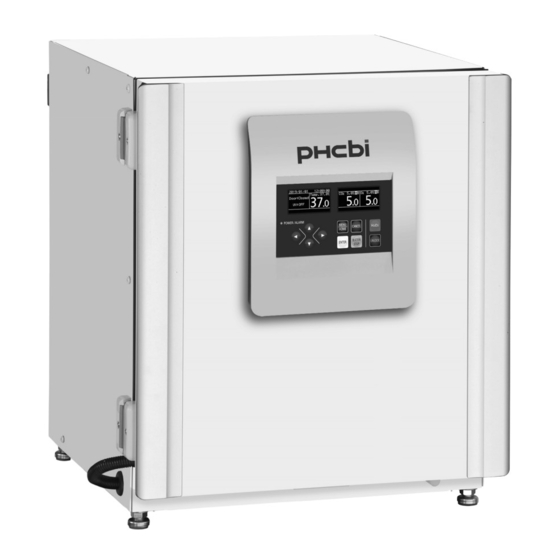
- Page 1 Operating Instructions Incubator MCO-50ML Please read the operating instructions carefully before using this product, and keep the operating instructions for future use. See page 101 for model number.
-
Page 2: Table Of Contents
CONTENTS INTRODUCTION ..................4 PRECAUTIONS FOR SAFE OPERATION ........... 5 LABELS ON INCUBATOR ................10 SYMBOLS ON INCUBATOR ..............11 ENVIRONMENTAL CONDITIONS ............. 11 INCUBATOR COMPONENTS ..............12 Unit ......................12 Control panel ..................14 Remote alarm terminal ................15 INSTALLATION ................... - Page 3 CONTENTS ELECTRIC LOCK (OPTION) ..............54 Setting door lock ..................54 Setting door lock delay time ..............55 Specifying the method to unlock the outer door ........56 Unlocking the outer door with a User ID ..........57 Unlocking the outer door during a power outage or malfunction ... 57 Registering user ID/password ...............
-
Page 4: Introduction
INTRODUCTION ■ Read the operating instructions carefully before using the product and follow the instructions for safe operation. ■ PHC Corporation takes no responsibility for safety if the product is not used as intended or is used with any procedures other than those given in the operating instructions. ■... -
Page 5: Precautions For Safe Operation
PRECAUTIONS FOR SAFE OPERATION It is imperative that the user complies with the operating instructions as they contain important safety advice. Items and procedures are described so that this unit can be used correctly and safely. Following these precautions will prevent possible injury to the user and any other person. Precautions are illustrated in the following way: WARNING Warning indicates a potentially hazardous situation which, if not avoided,... - Page 6 PRECAUTIONS FOR SAFE OPERATION WARNING Do not use the unit outdoors. Exposure to rain may cause leakage and/or electric shock. Only qualified engineers or service personnel should install the unit. The installation by unqualified personnel may cause electric shock or fire. Install the unit in a location capable of bearing the total combined weight (product + optional accessories + stored items).
- Page 7 PRECAUTIONS FOR SAFE OPERATION WARNING Before proceeding with maintenance or checking of the unit, set the power switch to OFF and disconnect the power supply plug. Performing the work while power is still flowing to the product or while the power-supply plug is still connected may give rise to electric shock and/or injury. Do not touch any electrical parts (such as power supply plug) or operate switches with a wet hand.
- Page 8 PRECAUTIONS FOR SAFE OPERATION WARNING If the unit is to be stored unused in an unsupervised area for a long period, ensure that children do not have access and that doors cannot be closed completely. Ask a qualified contractor to carry out disassembly and disposal of the unit. Leaving the unit in a location that can be accessed by third parties may result in unexpected accidents (e.g.
- Page 9 PRECAUTIONS FOR SAFE OPERATION CAUTION This unit must be plugged into a dedicated circuit protected by branch circuit breaker. Use a dedicated power source as indicated on the rating label attached to the unit. A multiple-tap may cause fire resulting from abnormal heating. Never store corrosive substances such as acid or alkali in this unit if the container cannot be sealed.
-
Page 10: Labels On Incubator
LABELS ON INCUBATOR Users are advised to read carefully the warnings and cautions contained on stickers at key locations on the interior and exterior of the incubator. Possible Warning/Caution Type Warning/Caution Label Description of Danger Danger Location of Danger Burns Avoid touching the cooling unit Hot Surface Cooling Unit &... -
Page 11: Symbols On Incubator
SYMBOLS ON INCUBATOR The following symbols are attached to the incubator: Attached to covers that access high-voltage electrical components to prevent electric shock. Only a qualified engineer or service personnel should be allowed to open these covers. Indicates an ultraviolet light (UV) caution. Indicates that caution is required. -
Page 12: Incubator Components
INCUBATOR COMPONENTS Unit Appearance Back side Interface board (Option) mounting location Display/ Control Panel USB port (⇒P14、 – (⇒P44 46、 – – Hooks (⇒P18) Handle 1 2 Leveling feet (⇒P18) 5 4 3 Tray (⇒P17) Inner door latch 6 ... - Page 13 INCUBATOR COMPONENTS 1. Access port: Used when routing cables such as the sensor cable of a measurement instrument into the chamber. Place the silicon caps on both the outside and inside of the port when the port is not used. 2.
-
Page 14: Control Panel
INCUBATOR COMPONENTS Control panel When sterilizing and cleaning the control panel, follow the precautions below. (1) Do not spray liquid on the control panel directly. (2) When sterilizing and cleaning, wipe the surface using a piece of gauze moistened with a proper amount of disinfectant (the amount that cannot form droplets). -
Page 15: Remote Alarm Terminal
INCUBATOR COMPONENTS Remote alarm terminal The alarm of this product can be transferred to a remote location by connecting the external alarm unit to the remote alarm terminal. For the behaviour of remote alarm output, refer to pages 86–90 The terminal of the remote alarm is provided at the back upper right of the unit (see the right figure). -
Page 16: Installation
INSTALLATION Installation site For correct operation of the incubator, install it in a location with the following conditions. Normal air environment Install the incubator in an environment with normal air. Do not expose to direct sunlight Do not install the incubator in a location where it will be exposed to direct sunlight. If the incubator is operated in direct sunlight, performance will be adversely affected. -
Page 17: Installation
INSTALLATION Installation 1. Remove the packing tape and clean up. Remove all the tapes securing the doors and the inner attachments. Open the doors to ventilate the chamber for a while. If the outer panels are dirty, use a cloth to wipe them with a diluted neutral detergent (Undiluted detergent can damage the plastic components. - Page 18 INSTALLATION 5. Adjust the leveling feet. Adjust leveling feet turning them anticlockwise until the incubator is level (Fig. 5). Note: Incubating on a sloping tray may adversely affect the cultivation. Shrink Stretch Leveling feet Fig. 5 6. Earth the incubator. Earth the incubator during installation to prevent electric shock.
-
Page 19: Connecting A Co Gas Cylinder
INSTALLATION Note: Before connecting a CO gas cylinder, read the precautions for safe operation on pages 5–9. Connecting a CO gas cylinder 1. Prepare a CO gas cylinder and attach the optional gas regulator MCO-010R. Notes: • Use a liquefied-CO gas cylinder (at least 99.5 % pure). - Page 20 INSTALLATION <When using the tube fitting> (1) Remove the hose joint from the gas regulator. (2) Attach the conversion bush using the packing or seal tape and then, attach the tube fitting. (3) Connect the gas regulator and the incubator using the gas tube that came with the incubator unit. Note: Wind the seal tape around the thread part only.
-
Page 21: Connecting N Gas Cylinders
INSTALLATION Note: Before connecting N gas cylinders (or O gas cylinders), read the precautions for safe operation on pages 5–9. Connecting N gas cylinders Depending on the setting of O density, the N or O gas cylinder should be selected. The selection is as follows: When the setting of O density is 18 % or less:... -
Page 22: Before Starting Operation
BEFORE STARTING OPERATION Initial cleaning method Before using the incubator for the first time, always thoroughly clean the chamber, inner attachments and humidifying pan (accessory) to remove dirt (tape residue, oil, etc.). Cleaning the chamber and humidifying pan are essential to ensure the utmost performance of the incubator. Use the following steps to properly clean the incubator. -
Page 23: Removing Inner Attachments
BEFORE STARTING OPERATION Removing inner attachments Remove the inner attachments through the following procedure. Be careful not to damage the UV lamp in the duct (When an optional UV system set MCO-170UVS is installed). 1. Turn OFF the power to the incubator. Tray 2. - Page 24 BEFORE STARTING OPERATION 6. Pull out the gas injection nozzle and gas injection Gas injection nozzle tube (Fig.5). nozzle tube Gas injection nozzle Fig.5 7. Pull out the fan (Fig. 6). Fig.6 8. Remove the silicon caps for the access port from the [Inside] Silicon cap interior and exterior (Fig.7 and Fig.8).
-
Page 25: Installing Inner Attachments
BEFORE STARTING OPERATION Installing inner attachments To reinstall all the attachments, perform the procedure in reverse order from step 8 on page 24. If the attachments are not inserted deep enough, the intended wind velocity performance cannot be achieved, and it may cause culture failure or insufficient decontamination. Note: When installing the fan, attach it to the motor 1. -
Page 26: Filling The Humidifying Pan
BEFORE STARTING OPERATION Filling the humidifying pan Use the following procedure to fill the humidifying pan with water or to replace water in it. 1. Pull out the humidifying pan (Fig. 1). 2. Dispose of the remaining water and clean the humidifying pan with a diluted detergent. -
Page 27: For Optimal Cultivation
FOR OPTIMAL CULTIVATION Precautions for cultures Leave space between culture containers. Always leave space for ventilation between culture containers (petri dishes, flasks, etc.). Inadequate spacing may result in uneven temperature distribution, CO gas density, and O gas density. Do not place harmful materials in the chamber. Never place samples that release acidic, alkaline, or corrosive gas into the chamber. -
Page 28: Preventing Contamination
FOR OPTIMAL CULTIVATION Preventing contamination To prevent contamination of the chamber, select a suitable installation site. Avoid locations with high temperatures or humidity where the air may contain more microorganisms. Do not place the incubator near doors, air conditioners, fans, etc, where draughts and passage of people may increase the risk of microorganisms entering the chamber. -
Page 29: Correct Operation
CORRECT OPERATION Use the following procedure to start trial operation or actual operation of the incubator. 1. Install the incubator correctly, referring to pages 16–21. 2. Remove the packing materials from the chamber and inner attachments. Then, clean and disinfect the chamber and all the inner attachments, referring to page 22. -
Page 30: Home Screen
HOME SCREEN The display consists of two parts (right side and left side). When the power is switched ON, the screen called "home screen" that shows the internal temperature, density, O density etc. is displayed. ① ② ③ ④ ⑤ ⑥ ... - Page 31 HOME SCREEN ⑮ ⑭ ⑫ ⑬ ⑰ ⑱ ⑯ <Right side of the display> <Left side of the display> ⑫ Outer door status display area ⑰ Error/warning display area Open: "Door:Open" is highlighted. Displays the current error/warning (see pages Closed: "Door:Closed"...
-
Page 32: Menu Screen
MENU SCREEN While the home screen is displayed, pressing the menu key (MENU/HOME) displays the Menu screen on the left side. The Menu screen consists of the following items: M e n u ① ... - Page 33 MENU SCREEN Following shows the screen display and function at each screen under Menu level. Note: The unit will return from setting mode to the home screen automatically after 90 seconds if no key is operated (auto-return function). In this case, the setting is not changed. Screen Function Page...
-
Page 34: Basic Parameters
BASIC PARAMETERS Setting temperature The chamber temperature during the normal operation of the incubator can be set as follows. The incubator automatically starts operation using these settings after power-on. Settable range: 0.0 C – 50.0 Factory setting: 37.0 1. -
Page 35: Setting Co 2 Gas
BASIC PARAMETERS Setting CO The CO gas control mode during the normal operation of the incubator can be set as follows. The incubator automatically starts operation using these settings after power-on. Setting values: ON or OFF Factory setting: OFF 1. -
Page 36: Setting Co Density
BASIC PARAMETERS Setting CO density The CO density during the normal operation of the incubator can be set as follows. The incubator automatically starts operation using these settings after power-on. Settable range: 0.0 % – 20.0 % (When the setting is 0.0 %, the CO ON/OFF becomes “OFF”) ... -
Page 37: Setting O 2 Gas
BASIC PARAMETERS Setting O The O gas control mode during the normal operation of the incubator can be set as follows. The incubator automatically starts operation using these settings after power-on. Setting values: ON or OFF Factory setting: OFF 1. -
Page 38: Setting O Density
BASIC PARAMETERS Setting O density The O density during the normal operation of the incubator can be set as follows. The incubator automatically starts operation using these settings after power-on. Settable range: 1.0 % – 18.0 %, 22.0 % – 80.0 % ... -
Page 39: Setting High Limit Temperature Alarm
BASIC PARAMETERS Setting high limit temperature alarm The high limit temperature alarm is different from the temperature alarm (page 61), and it is independent temperature alarm. When the chamber temperature exceeds the temperature set for the high limit temperature alarm, this alarm activates. The high limit temperature for the normal incubator operation can be set as follows. -
Page 40: Automatic N ) Gas Cylinder Switching
BASIC PARAMETERS Automatic N ) gas cylinder switching By using this function, the empty N gas (O gas) cylinder can be automatically switched to the other one, when the N gas (O gas) cylinder being used becomes empty. 1. When N gas is remaining in N gas cylinder A, the unit operates using N gas supplied from... -
Page 41: Manual N 2 (O 2 ) Gas Supply Line A/B Switching
BASIC PARAMETERS Manual N ) gas supply line A/B switching The N gas supply lines A and B can be switched manually at any time. Setting values: A or B Factory setting: A 1. On the home screen, press the menu key (MENU/HOME). Menu ▶... -
Page 42: Operation/Alarm Log
OPERATION/ALARM LOG Displaying operation log The product's operation history can be graphically displayed on the display. Furthermore, it is possible to export these records to USB flash drive. Menu Graph display setting: Internal temperature, CO density, O density, Set Value and the door opening/closing records. - Page 43 OPERATION/ALARM LOG *When you press the up/down keys (△▽) while in the graph screen with the graph item on the upper left of the screen highlighted [Fig. 5], the range of the vertical axis of the graphs changes as shown in the table. Graph item Display range 60°C –...
- Page 44 OPERATION/ALARM LOG 9. Press the enter key (ENTER). ▶ The log data on the selected date is displayed in a graph. *If the entered setting value is out of the settable range, the following message is displayed on the right side of the display.
-
Page 45: Exporting Operation Log
OPERATION/ALARM LOG Exporting operation log The temperature in the chamber, CO density, O density, or door opening/closing records can be exported to a USB flash drive. Setting values: All or Specified date (1 day only) 1. Insert the USB flash drive into the USB port. Note: USB flash drives with capacity of 32 GB or less that employ the Menu FAT16/FAT32 file system are supported. - Page 46 OPERATION/ALARM LOG 8. When the export is complete, "Export complete" is displayed [Fig. 6]. Press any key to return to the Data Log Export screen. Export complete Note: The operation log data saved in the incubator is not deleted even after the completion of the export.
-
Page 47: Setting Log Interval
OPERATION/ALARM LOG Setting log interval This product has a function for storing operation history data (records of temperatures in the chamber, CO densities, O densities, and door openings/closings). The log recording interval is set in the following way: Setting range: every 2 – 15 minutes ... -
Page 48: Setting Unique Id
OPERATION/ALARM LOG Setting Unique ID You can set the unique device ID that will be a part of the file name (CSV file) exported to the USB flash drive. Setting values: 6 digits of alphanumeric characters (capital letters only if using letters) ... -
Page 49: Displaying Alarm Log
OPERATION/ALARM LOG Displaying alarm log This product has a function for storing alarm history (maximum 256 cases). The alarm history stored in this product can be displayed on the display. Note: When the alarm history records reach to more than 256, the oldest record is deleted. Alarm Gas Empty 02/Jan/19 22:00 E01 ▲... -
Page 50: Exporting Alarm Log
OPERATION/ALARM LOG Exporting alarm log The alarm history data stored in this product can be exported to a USB flash drive in CSV format. Setting values: All or Specified date (1 day only) 1. Insert the USB flash drive into the USB port. Note: USB flash drives with capacity of 32 GB or less that employ the Menu FAT16/FAT32 file system are supported. - Page 51 OPERATION/ALARM LOG 8. When the export is complete, "Export complete" is displayed [Fig. 6]. Press any key to return to the Alarm Export screen. Export complete Note: The alarm log data saved in the incubator is not deleted even after the completion of the export.
-
Page 52: Key Lock Function
KEY LOCK FUNCTION Setting key lock The keys can be locked to prevent the setting from being incorrectly changed. If the key lock is set to ON, the settings cannot be changed even if the keys on the control panel are pressed. ... -
Page 53: Cancelling Key Lock
KEY LOCK FUNCTION 8. Press the menu key (MENU/HOME) to return to the home screen. The display returns to the home screen automatically when 90 seconds has passed without any key operation. Cancelling key lock When the key lock is set to OFF, it is possible to change the settings. Menu LOCK 1. -
Page 54: Electric Lock (Option)
ELECTRIC LOCK (OPTION) The outer door can be automatically locked by the electric lock when specified amount of time has elapsed after closing the outer door. To use this door lock function, the electric lock MCO-170EL (optional accessory) should be installed on the unit. Setting door lock The setting of the door lock function is as follows. -
Page 55: Setting Door Lock Delay Time
ELECTRIC LOCK (OPTION) Setting door lock delay time You can specify the amount of time until the outer door is automatically locked after closing the door (door lock delay time). Settable range: 0 – 60 minutes (when the setting is 0 minutes, the Door Lock ON/OFF becomes “OFF.”) ... -
Page 56: Specifying The Method To Unlock The Outer Door
ELECTRIC LOCK (OPTION) Specifying the method to unlock the outer door The User ID ON/OFF setting specifies the method for unlocking the outer door when it is locked. Method 1. When the User ID is set to ON: Press the Unlock key (UNLOCK), and then enter the user ID and the password to unlock the outer door. -
Page 57: Unlocking The Outer Door With A User Id
ELECTRIC LOCK (OPTION) Unlocking the outer door with a User ID Press the Unlock key (UNLOCK), and then enter the user ID to unlock the outer door. This procedure is as follows. *The User ID must be set to ON to use this method for unlocking the outer door. 1. -
Page 58: Registering User Id/Password
ELECTRIC LOCK (OPTION) Registering user ID/password You can register user IDs and passwords for unlocking the outer door. Use the following steps to set the values. Setting value Menu User ID: 6-digit alphanumeric characters (only capital Set Value letters are available for alphabetic characters). Data Log Password: 6-digit number Lock... - Page 59 ELECTRIC LOCK (OPTION) 6. Move the cursor to select each digit of the password (6 digits) with the Confirm Password left/right keys (◁▷), set the numerical values using the up/down keys (△▽), and then press the Enter key (ENTER). ***** ▶ The Confirm Password screen is displayed [Fig.
-
Page 60: Deleting User Ids
ELECTRIC LOCK (OPTION) Deleting User IDs The user ID registered to unlock the outer door can be deleted. Use the following steps to delete the user ID. 1. Press the Menu key (MENU/HOME) while the Home screen is Menu displayed. Set Value ▶ The left side of the display switches to the Menu screen. -
Page 61: Alarm Parameters
ALARM PARAMETERS Setting temperature alarm When the temperature goes out of the preset range (the set chamber temperature ± the set temperature alarm value), the alarm activates. The temperature alarm value can be set as follows. Settable range: ±1.0 C – ±5.0 ... -
Page 62: Setting Temperature Alarm Delay
ALARM PARAMETERS Setting temperature alarm delay This function delays the activation of the temperature alarm for the preset amount of time. Settable range: 0 – 15 minutes Factory setting: 15 minutes 1. On the home screen, press the menu key (MENU/HOME). Menu ▶... -
Page 63: Setting Co Density Alarm
ALARM PARAMETERS Setting CO density alarm When the CO density goes out of the preset range (the set CO density ± the set CO density alarm value), the alarm activates. Settable range: ±0.5 % – ±5.0 % Factory setting: ±1.0 % ... -
Page 64: Setting Co Density Alarm Delay
ALARM PARAMETERS Setting CO density alarm delay This function delays the activation of the CO density alarm for the preset amount of time. Settable range: 0 – 15 minutes Factory setting: 15 minutes 1. On the home screen, press the menu key (MENU/HOME). Menu ▶... -
Page 65: Setting O Density Alarm
ALARM PARAMETERS Setting O density alarm When the O density goes out of the preset range (the set O density ± the set O density alarm value), the alarm activates. Settable range: ±0.5 % – ±5.0 % Factory setting: ±1.0 % ... -
Page 66: Setting O Density Alarm Delay
ALARM PARAMETERS Setting O density alarm delay This function delays the activation of the O density alarm for the preset amount of time. Settable range: 0 – 60 minutes Factory setting: 30 minutes 1. On the home screen, press the menu key (MENU/HOME). Menu ▶... -
Page 67: Setting Door Alarm Delay
ALARM PARAMETERS Setting door alarm delay This function delays the activation of the door alarm for the preset amount of time. Settable range: 1 – 30 minutes Factory setting: 2 minutes 1. On the home screen, press the menu key (MENU/HOME). Menu ▶... -
Page 68: Setting Ring Back Delay
ALARM PARAMETERS Setting ring back delay This function reactivates the alarm when the alarm state still continues and preset amount of time has elapsed after the BUZZER STOP key was pressed to stop the alarm buzzer. Settable range: 0 – 99 minutes (when the setting is 0 minutes, the Ring Back Delay becomes ... -
Page 69: Setting Remote Alarm
ALARM PARAMETERS Setting remote alarm You can set the behavior of the remote alarm when the BUZZER STOP key on the incubator unit is pressed. When set to ON (not linked): The alarm on the remote alarm device does not stop even when the alarm BUZZER STOP key is pressed during the alarm buzzer activation. -
Page 70: Uv Lamp (Option)
UV LAMP (OPTION) When the optional UV System MCO-170UVS is installed on the model MCO-50ML, the UV lamp lights for preset amount of time after closing the outer door to disinfect the water in the humidifying pan and the air circulating in the chamber. -
Page 71: Setting Uv Lamp On Period
UV LAMP (OPTION) Setting UV lamp ON period To change the UV lamp ON period, follow the procedure below. Settable range: 0 – 30 minutes Factory setting: 10 minutes Notes: ・The recommended UV lighting time (UV Lighting Time) is 10 minutes. Less than 10 minutes may reduce the bactericidal effect. -
Page 72: Uv Lamp Life Indication
UV LAMP (OPTION) UV lamp life indication The amount of time the UV lamp has been used up to now relative to the total amount of time recommended for the replacement of the UV lamp (5,000 hours) is displayed in percentage (%). 1. -
Page 73: Automatic Extension Of Uv Lamp On Period
UV LAMP (OPTION) Automatic extension of UV lamp ON period The amount of UV irradiation decreases as the total UV lamp ON period increases. To compensate for this, UV lamp ON period is automatically extended as the total UV lamp ON period increases (the value set for UV Lighting Time is not changed). -
Page 74: Lighting Uv Lamp For 24 Hours
UV LAMP (OPTION) Lighting UV lamp for 24 hours If contamination occurs in the chamber due to accumulation of dirt or the culture medium being scattered etc., sterilize it by 24-hour continuous UV irradiation as described in the following procedure: ... -
Page 75: Gas Auto Changer (Option)
GAS AUTO CHANGER (OPTION) When the optional gas auto changer MCO-50GC is installed, two connecting ports for CO gas pipes, A and B are available. If two CO gas cylinders are connected, the CO gas supply line can be switched when one of the CO gas cylinders becomes empty. - Page 76 GAS AUTO CHANGER (OPTION) When the CO density level in the chamber remains unchanged even though the CO gas valve in the unit is open, the unit assumes the currently connected CO gas cylinder to be empty and automatically switches the CO gas supply line to the other one.
-
Page 77: Manual Co 2 Gas Supply Line A/B Switching
GAS AUTO CHANGER (OPTION) Manual CO gas supply line A/B switching The CO gas supply lines A and B can be switched manually at any time. Setting values: A or B Factory setting: A 1. On the home screen, press the menu key (MENU/HOME). Menu ▶... -
Page 78: Other Parameters
OTHER PARAMETERS Setting date display format The date display format can be set as follows. Setting values: DD/MM/YY (Day/Month/Year) or YY/MM/DD (Year/Month/Day) Factory setting: DD/MM/YY 1. On the home screen, press the menu key (MENU/HOME). Menu ▶ The left side of the display changes to the Menu screen. Set Value Data Log Lock... -
Page 79: Setting Date
OTHER PARAMETERS Setting date The date setting can be changed as follows. 1. On the home screen, press the menu key (MENU/HOME). Menu ▶ The left side of the display changes to the Menu screen. Set Value Data Log Lock 2. -
Page 80: Setting Time
OTHER PARAMETERS Setting time The time setting can be change as follows. 1. On the home screen, press the menu key (MENU/HOME). Menu ▶ The left side of the display changes to the Menu screen. Set Value Data Log Lock 2. -
Page 81: Setting Keypad Clicking Sound
OTHER PARAMETERS Setting keypad clicking sound The key operation sound can be set as follows. Setting values: ON or OFF Factory setting: ON 1. On the home screen, press the menu key (MENU/HOME). Menu ▶ The left side of the display changes to the Menu screen. Set Value Data Log Lock... -
Page 82: H 2 O 2 Decontamination (Option)
DECONTAMINATION (OPTION) When the chamber is contaminated or when cleaning the chamber prior to starting a culture, H decontamination can be performed. Prior to the H decontamination work, make sure that MCO-170UVS (UV system set), MCO-50HP (H generator), MCO-50HB (H decon kit), and MCO-170EL (electric lock) are all installed on your incubator. - Page 83 DECONTAMINATION (OPTION) 8. Set the humidifying pan removed in step 1 by leaning it against the flange of the duct. Set the trays Humidifying on the first and third tray catches from the top (Fig. 3). Note: H decontamination function decontaminates Duct flange the chamber and inner attachments.
- Page 84 DECONTAMINATION (OPTION) *If an error occurs during the Decontamination system check, the error screen is Temp. Decon Failed. displayed [Fig. 9]. Door : Closed 37.0 Please Remove Check the error, and then stop the UV : OFF product and contact our sales Unit.
- Page 85 DECONTAMINATION (OPTION) *If the H decontamination is Decontamination Step 3 : UV Resolve terminated or ends in error, the Door : Look Step 1 error number, error code, and error Step 2 message is displayed after UV : ON Step 3 decontamination [Fig.
-
Page 86: Alarms, Safety, And Self-Diagnosis
ALARMS, SAFETY, AND SELF-DIAGNOSIS This product has the following warning, safety, and self diagnosis functions. When the alarm function or the self-diagnosis function activates, an error code and error message will be displayed on the display. Error: Performance for culture and decontamination has decreased sharply. Stop the product and contact our sales representative or agent unless you know the cause of the error and you can expect the recovery. - Page 87 ALARMS, SAFETY, AND SELF-DIAGNOSIS OLED Display Remote Safety Alarm type Buzzer Message Error code alarm operation Main heater burnout occurs or the main heater SSR is Err 13: Main Heater Error Main heater error short-circuited. Bottom heater burnout occurs or the bottom heater SSR is Err 14: Humidity Heater Error Bottom heater error short-circuited.
- Page 88 ALARMS, SAFETY, AND SELF-DIAGNOSIS Error codes during H decontamination OLED Display Remote Safety Alarm type Buzzer Message Error code alarm operation The H generator is Err 31:H Unit Not Found not connected. There is no H System check error solution or the H level Err 32:Low H...
- Page 89 ALARMS, SAFETY, AND SELF-DIAGNOSIS Warning: Performance for culture may decrease. If it is a temporary situation due to operations, wait for recovery. Otherwise, contact our sales representative or agent. OLED Display Remote Safety Alarm type Buzzer alarm operation Warning Message The chamber’s Temperature exceeds High limit...
-
Page 90: Routine Maintenance
ALARMS, SAFETY, AND SELF-DIAGNOSIS Tables 6–8 show the behaviour of the alarm (buzzer) and ring back function when pressing the BUZZER STOP key. Table 6. In cases other than those covered in Tables 7 and 8 Buzzer from CO incubator Remote Alarm Ring Back... -
Page 91: Troubleshooting
TROUBLESHOOTING If the incubator does not seem to be working properly, check the following items before calling for service. Problem Items to be checked and countermeasures Is the incubator plugged in? The incubator does not operate at all. Is there a power outage, or has a circuit breaker interrupted the power? ... - Page 92 TROUBLESHOOTING Problem Items to be checked and countermeasures Are the outer and inner doors being frequently opened and closed? A large quantity of gas is being consumed. Check whether gas is leaking from connectors due to deterioration of the gas tube, or whether there may be any pinhole leaks.
- Page 93 TROUBLESHOOTING Problem Items to be checked and countermeasures Contact our sales representative or agent when you cannot start H Cannot start H decontamination decontamination (Cannot select "YES" in Fig.4 on even if the H decon kit MCO-50HB is installed. page 83).
-
Page 94: Disposal Of Unit
DISPOSAL OF UNIT Before disposal of this O incubator, contact our sales representative or agent for further information. Improper handling of biohazardous waste can result in accidental exposure to infectious agents. If there is a danger of biohazard, decontaminate the incubator as thoroughly as possible before disposal. 廢電池... - Page 95 DISPOSAL OF UNIT Likvidácia opotrebovaných zariadení a batérií Disposal of Old Equipment and Batteries Len pre Európsku úniu a krajiny so systémom recyklácie Only for European Union and countries with recycling systems Tieto symboly uvádzané na výrobkoch, balení a/alebo v These symbols on the products, packaging, and/or sprievodnej dokumentácii...
- Page 96 DISPOSAL OF UNIT Likvidace použitých zařízení a baterií Vanhojen laitteiden ja paristojen hävittäminen Jen pro státy Evropské unie a země s fungujícím systémem recyklace a Vain EU-jäsenmaille ja kierrätysjärjestelmää käyttäville maille zpracování odpadu. Tämä symboli tuotteissa, pakkauksessa ja/tai asiakirjoissa Tyto symboly na výrobcích, jejich obalech a v doprovodné tarkoittaa, että...
- Page 97 DISPOSAL OF UNIT Smaltimento di vecchie apparecchiature e batterie usate Eliminação de Equipamentos Usados e Baterias Solo per Unione Europea e Nazioni con sistemi di raccolta e Apenas para a União Europeia e países com sistemas de reciclagem smaltimento Estes símbolos produtos, embalagens,...
- Page 98 DISPOSAL OF UNIT Avfallshantering av produkter och batterier Brukerinformasjon om innsamling av gammelt utstyr og brukte Endast för Europeiska Unionen och länder med återvinningssystem batterier Dessa symboler på produkter, förpackningar och/eller Bare for EU og land med retursystemer Slike symboler på produkter, emballasje, og/eller på medföljande dokument betyder att förbrukade elektriska medfølgende dokumenter...
-
Page 99: Specifications
SPECIFICATIONS Product name Incubator MCO-50ML External dimensions W 480 mm x D 550 mm x H 585 mm (W 18.9 in. x D 21.7 in. x H 23.0 in.) Internal dimensions W 370 mm x D 363 mm x H 385 mm (W 14.6 in. x D 14.3 in. x H 15.2 in.) Interior volume 50 L (1.77 cu.ft.) - Page 100 SPECIFICATIONS Table 9. Optional accessories For UV disinfection UV system set (MCO-170UVS) UV system set (MCO-170UVS) Electric lock (MCO-170EL) For H decontamination generator (MCO-50HP) decon kit (MCO-50HB) reagent (MCO-5H2O2) For locking the outer door Electric lock (MCO-170EL) Double-stacking bracket (MCO-170PS) Stacking plate (MCO-50SB) Roller base (MCO-50RB) Gas regulator (MCO-010R)
-
Page 101: Performance
PERFORMANCE Product name Incubator MCO-50ML Model number MCO-50ML-PE Temperature control range Ambient temperature plus 5 C to max. 50 (ambient temperature: 5 C to 35 Temperature distribution ±0.25 C (ambient temperature: 23 C, setting: 37 C, CO : 5 %, O... -
Page 102: Safety Check Sheet
SAFETY CHECK SHEET Please fill in this form before servicing. CAUTION Hand over this form to the service engineer for their and your safety. Safety check sheet 1. Stored material □ □ □ Risk of infection: Maybe □ □ □ Risk of toxicity: Maybe □... - Page 103 MEMO 103 ...
- Page 104 Printed in Indonesia 1-1-1 Sakada, Oizumi-machi, Ora-gun, Gunma 370-0596, Japan LDCL064700-0 N1020-0 © PHC Corporation 2020...
Need help?
Do you have a question about the MCO-50ML and is the answer not in the manual?
Questions and answers