Table of Contents
Advertisement
Please read the operating instructions carefully before using this product, and keep the operating
instructions for future use.
See page 39 for model number.
This product is for research use only.
Not for clinical diagnosis or treatment of humans or animals.
Operating Instructions
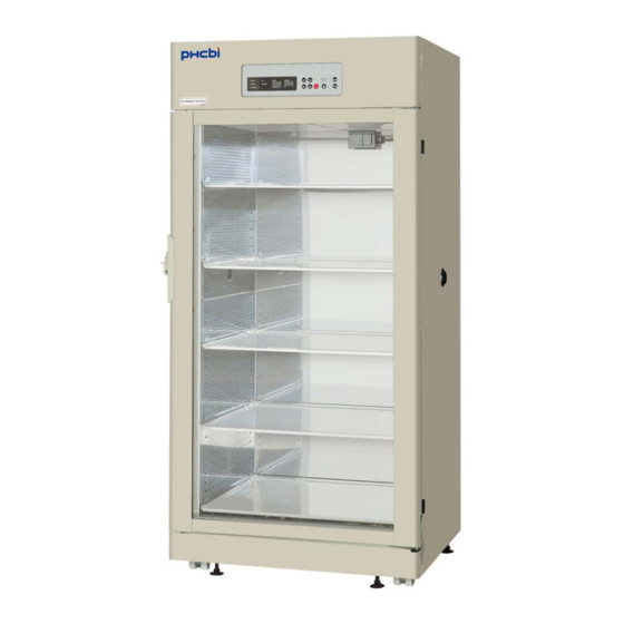
MCO-80ICL
CO
Incubator
2
Advertisement
Table of Contents

Related Manuals for Phcbi MCO-80ICL


Summary of Contents for Phcbi MCO-80ICL
- Page 1 Operating Instructions Incubator MCO-80ICL This product is for research use only. Not for clinical diagnosis or treatment of humans or animals. Please read the operating instructions carefully before using this product, and keep the operating instructions for future use. See page 39 for model number.
-
Page 3: Table Of Contents
CONTENTS INTRODUCTION ....................2 PRECAUTIONS FOR SAFE OPERATION ............3 LABELS ON UNIT ....................7 ENVIRONMENTAL CONDITIONS ..............8 INCUBATOR COMPONENTS ................9 Control panel and keypad ................12 Remote alarm terminal ................... 14 INSTALLATION SITE ..................15 INSTALLATION ....................16 Connection of CO gas cylinder .............. -
Page 4: Introduction
INTRODUCTION ■ Read the operating instructions carefully before using the Product and follow the instructions for safety operation. ■ PHC Corporation disavows any responsibility for safety if the Product is used for other than the intended use or used with any procedures other than those given in the operating instructions. ■... -
Page 5: Precautions For Safe Operation
PRECAUTIONS FOR SAFE OPERATION It is imperative that the user complies with the operating instructions as it contains important safety advice. Items and procedures are described so that you can use this unit correctly and safely. If the precautions advised are followed, this will prevent possible injury to the user and any other person. - Page 6 PRECAUTIONS FOR SAFE OPERATION USA Only (Model with a lamp): This product has a lamp that contains mercury. Disposal may be regulated in your community due to environmental considerations. For disposal or information, please visit PHC website: https://www.phchd.com. Contains mercury / Contenu avec mercure For more information on safe handling Pour plus de renseignements sur les procedures, the measures to be taken in...
- Page 7 WARNING Do not use the unit outdoors. Current leakage or electric shock may result if the unit is exposed to rain water. Only qualified engineers or service personnel should install the unit. The installation by unqualified personnel may cause electric shock or fire. Install the unit on a sturdy floor and take an adequate precaution to prevent the unit from turning over.
- Page 8 PRECAUTIONS FOR SAFE OPERATION WARNING Ensure you do not inhale or consume medication or aerosols from around the unit at the time of maintenance. These may be harmful to your health. Never splash water directly onto the unit as this may cause electric shock or short circuit. Never put containers with liquid on the unit as this may cause electric shock or short circuit when the liquid is spilled.
-
Page 9: Labels On Unit
CAUTION This unit must be plugged into a dedicated circuit protected by branch circuit breaker. Use a dedicated power source as indicated on the rating label attached to the unit. A multiple-tap may cause fire resulting from abnormal heating. Never store corrosive substances such as acid or alkali in this unit if the container cannot be sealed. -
Page 10: Environmental Conditions
ENVIRONMENTAL CONDITIONS This equipment is designed to be safe at least under the following conditions (based on the IEC 61010-1): ■ Indoor use; ■ Altitude up to 1000 m; ■ Temperature 5 C to 40 ■ Maximum relative humidity 80 % for temperature up to 31 C decreasing linearly to 50 % relative humidity at 40 ■... -
Page 11: Incubator Components
INCUBATOR COMPONENTS 6 (inner face of ceiling) Rear upper side Upper left side 13, 14 Bottom of chamber When the bottom cover is removed 18,19... - Page 12 INCUBATOR COMPONENTS 1. Outer door: Sticks to frame with magnetic seal. Door heater is installed in the door panel. The door window is double glass. 2. Leveling foot: Screw type for adjusting the height. Adjust the foot so that the unit can be level. 3.
- Page 13 24. Water reservoir: Use sterile distilled water of approximately 20 L to fill the water reservoir. 25. Water level sensor for water reservoir: Detects the water level in the water reservoir. 26. Auto water supply inlet: When an optional component MCO-80AS (auto water supply system) is installed, water is supplied from here.
-
Page 14: Control Panel And Keypad
INCUBATOR COMPONENTS Control panel and keypad 1. Digital temperature indicator (TEMPERATURE C): Normally, this indicator shows the chamber temperature. In the setting mode, it shows the set value of the chamber temperature. If the self diagnostic function detects any abnormality, an error code will be displayed. 2. - Page 15 16. Upper limit alarm reset key (RESET): Press this key while the over heat lamp blinks to reset the alarm. 17. Enter key (ENT): Pressing this key memorizes the set value in the controller. 18. Numerical value shift key ( ): Pressing this key in the setting mode causes the numerical value to shift.
-
Page 16: Remote Alarm Terminal
INCUBATOR COMPONENTS Remote alarm terminal The remote alarm terminal is located at the upper left side of the unit. Remote Alarm The remote alarm terminal is a contact output. MAX. DC 30 V, 2 A Normal : Open between COM to N.O. Close between COM to N.C. -
Page 17: Installation Site
INSTALLATION SITE To operate this unit properly and to obtain maximum performance, install the unit in a location with the following conditions: ■ A location not subjected to direct sunlight Do not install the unit under direct sunlight. Installation in a location subjected to direct sunlight cannot obtain the intended performance. -
Page 18: Installation
INSTALLATION SITE ■ Altitude up to 1000 m It is necessary to replace the outer glass door with specific one when the unit is used at an altitude of 1000 m or higher. If the unit needs to be airfreighted, consult with our sales representative or agent. INSTALLATION 1. -
Page 19: Connection Of Co Gas Cylinder
Connection of CO gas cylinder WARNING Check the gas type and ensure that it is fit for the purpose. Make sure that all pipes are connected correctly and are not liable to become disconnected. Ensure that the gas pressure is set at the specified value. -
Page 20: Cautions For Using Equipment In Chamber
CAUTIONS FOR USING EQUIPMENT IN CHAMBER ● Use the inner outlet for an equipment used in the chamber For power source of a heat emitting equipment used in the chamber such as a shaker or a bottle roller, use the electrical outlet equipped in the product. In case of that the chamber temperature rises too much due to this heat emission, when it reaches the preset temperature of over heating protection, electricity through the outlet is cut automatically to avoid over heating in the chamber. -
Page 21: Prevent Contamination
PREVENT CONTAMINATION To prevent contamination of the chamber, select an appropriate location for installation as well as the complete disinfection of the chamber components. ● Avoid hot and humid location Avoid location with high temperature and/or humidity as the presence of bacteria in the air is greater than in normal environment. -
Page 22: Cautions For Culture
CAUTIONS FOR CULTURE ● Do not subject to direct air flow Do not allow the air for air conditioning to hit the unit or door directly. Direct hit may cause condensation or contamination. ● Tray Make sure to set the bottom tray to the bottom position of side duct with tray support. This may cause condensation on bottom cover by varying air flow inside chamber. -
Page 23: Start-Up Of Unit
START-UP OF UNIT When start the test operation or the operation, follow these steps as below. 1. Install the unit referring to “INSTALLATION” on page 16. 2. Remove all transportation packaging materials and tapes. Then clean and sterilize the chamber and internal attachments. -
Page 24: Setting Of Chamber Temperature And Co Density
SETTING OF CHAMBER TEMPERATURE AND CO DENSITY Table below shows the basic procedure for setting the chamber temperature and CO density. The upper limit alarm temperature setting is also shown in the table. Perform key operations in the sequence indicated in the table. The example in the table is based on the assumption that the desired temperature is 37 C and CO density is 5 %. - Page 25 This product usually operates in approximately Mode Function 80 %R.H. setting. For approximately 90 %R.H. No humidifying mode No humidifying operation, the high humidity mode needs to be Normal mode Inner humidity 80 %R.H. set (the normal mode is set as default setting High humidity mode Inner humidity 90 %R.H.
- Page 26 SETTING OF CHAMBER TEMPERATURE AND CO DENSITY ● In each setting mode, the indicator returns to the current temperature and CO density display mode automatically when 90 seconds has passed without any key operation. ● Do not use the calibration key (CAL) on the control panel when the unit is under normal conditions. The unit enters calibration mode by pressing this key.
-
Page 27: Key Lock Function
KEY LOCK FUNCTION This unit is provided with a key lock function. When the key lock is ON, change of temperature or CO density setting through the key pad is not available. Note: The factory default setting value is OFF(L0). Display Mode Function... -
Page 28: Alarms & Safety Functions
ALARMS & SAFETY FUNCTIONS This unit has the alarms and safety functions shown in the table below, and also self diagnostic functions. Alarms and safety functions Alarm & Safety Situation Indication Buzzer Safety operation Over heat lamp lights. If the chamber temperature exceeds Upper limit E12 or E16 and chamber Heater OFF... - Page 29 Alarm & Safety Situation Indication Buzzer Safety operation E14 is displayed alternately Door heater If the door heater or the door heater with the temperature on the Intermittent tone Remote alarm abnormality relay goes open circuit. digital temperature indicator. E15 is displayed alternately Sensor box heater If the sensor box heater or the sensor with the temperature on the...
-
Page 30: Setting Of Alarm Resume Time
SETTING OF ALARM RESUME TIME The buzzer is silenced by pressing alarm buzzer stop key (BUZZER) on the control panel during alarm condition. The buzzer will be activated again after certain suspension if the alarm condition is continued. The suspension time can be set by following the procedure shown in the table below. The example in the table is based on the assumption that the desired duration is 20 minutes. -
Page 31: Routine Maintenance
ROUTINE MAINTENANCE WARNING Always disconnect the power supply to the unit prior to any repair or maintenance of the unit in order to prevent electric shock or injury. The water level sensor periodically generates heat at around 70 C that may be cause of burn injury. Ensure you do not inhale or consume medication or aerosols from around the unit at the time of maintenance. - Page 32 ROUTINE MAINTENANCE 5. Remove screws of the side ducts to dismount four side ducts. See Fig.4. 6. Remove screws at the lower both side to remove the front panel lower cover (Fig.5). Open the drain cock to drain all humidifying water, and it will drain through the drain outlet (Fig.6). Wipe off remained water with a dry gauze.
-
Page 33: Filling Water Reservoir
Filling water reservoir To fill the water reservoir, do the following: 1. Open the outer door and remove the lowest tray. See Fig.1. 2. Remove a screw in front side and rotate the water supply inlet cover to open the water supply inlet. See Fig.2. -
Page 34: Calibration Temperature Calibration
CALIBRATION Temperature calibration 1. Press the calibration key (CAL) for approximately 5 seconds. 2. The third digit of the digital temperature indicator flashes, and the digital CO density indicator goes out. 3. Set the present correct temperature with the digit shift key ( ) and numerical value shift key ( then press the enter key (ENT). -
Page 35: Co 2 Calibration
calibration Span setting Span setting should be done under stable condition of temperature, humidity, and CO density. 1. Press the calibration key (CAL) for about 5 seconds. 2. The third digit on the digital temperature indicator flashes, and the digital CO density indicator goes out. -
Page 36: Troubleshooting
TROUBLESHOOTING If the unit malfunctions, check out the following before calling for service. Malfunction Check/Remedy • The unit is not plugged correctly into a power outlet. The unit does not operate • The circuit breaker at the power source is active or a power failure at all. -
Page 37: Disposal Of Unit
Note: If the malfunction is not eliminated after checking the chart in the preceding page, or the malfunction is not shown in the chart, contact our sales representative or agent. DISPOSAL OF UNIT WARNING If the unit is to be stored unused in an unsupervised area for an extended period ensure that children do not have access and doors cannot be closed completely. -
Page 38: Automatic Co Cylinder Changeover
AUTOMATIC CO CYLINDER CHANGEOVER Gas auto changer (MCO-80GC) is available as an optional accessory. This system switches the gas supply line when one CO gas cylinder is empty. Note: The installation of MCO-80GC should be implemented by a qualified service personnel. After attachment of MCO-80GC, do the following: 1. -
Page 39: Auto Water Supply System
AUTO WATER SUPPLY SYSTEM Auto water supply system (MCO-80AS) is Function available as an optional accessory. Automatic water supply OFF(default) This system kit supplies water from its tank Automatic water supply ON automatically when water level alarm lamp(RH PAN) blinks due to decrease the water in the water reservoir. -
Page 40: Specifications
SPECIFICATIONS Product name Incubator MCO-80ICL W986 mm x D853 mm x H2,040 mm (without caster; H1,975 mm) External dimensions W806 mm x D693 mm x H1,524 mm Internal dimensions 851 L Interior volume Painted steel Exterior Stainless steel containing copper... -
Page 41: Performance
PERFORMANCE Incubator MCO-80ICL Product name MCO-80ICL-PA Model number Ambient temperature +5 C to 50 C (ambient temperature; 20 C to 35 Temperature control range ±0.5 C (ambient temperature; 25 C, setting; 37 C, 5 %, no load) Temperature distribution ±0.1 C (ambient temperature;... -
Page 42: Safety Check Sheet
CAUTION Please fill in this form before servicing. Hand over this form to the service engineer to keep for his and your safety. Safety check sheet 1. Incubator contents : □ □ Risk of infection: □ □ Risk of toxicity: □... - Page 44 1-1-1 Sakada, Oizumi-machi, Ora-gun, Gunma 370-0596, Japan Printed in Japan LDCL041600-0 © PHC Corporation 2018 S0418-0...
Need help?
Do you have a question about the MCO-80ICL and is the answer not in the manual?
Questions and answers