Emerson Fisher 785C Instruction Manual
Piston actuators
Hide thumbs
Also See for Fisher 785C:
- Instruction manual (32 pages) ,
- Instruction manual supplement (9 pages)
Table of Contents
Advertisement
Quick Links
Instruction Manual
D104483X012
Fisher
785C Piston Actuators
™
Contents
. . . . . . . . . . . . . . . . . . . . . . . . . . . . . . . . .
. . . . . . . . . . . . . . . . . . . . . . . . . . . . .
. . . . . . . . . . . . . . . . . . . . . . . . . . . . . . . . .
. . . . . . . . . . . . . . . . . . . . . . . . . . . . . . .
. . . . . . . . . . . . . . . . . . . . . . . . . . . . . . . . . .
. . . . . . . . . . . . . . . . . . . . . . . . . . . . .
. . . . . . . . . . . . . . . . . . . . . . . . . . .
. . . . . . . . . . . . . . . . . . . . . . . . . . . . . . . .
. . . . . . . . . . . . . . . . . . . . . . . . . .
. . . . . . . . . . . . . . . . . . . . . . . . . . . . . . . .
. . . . . . . . . . . . . . . . . . . . . . . . . . . . .
. . . . . . . . . . . . . . . . . . . . . . . . . . . . . . .
. . . . . . . . . . . . . . . . . . . . . . . . . . . . . . . . . . .
. . . . . . . . . . . . . . . . . . . . . . . . . . . . . . . . . . .
. . . . . . . . . . . . . . . . . . . . . . . . . .
Introduction
Scope of Manual
This instruction manual includes installation, maintenance, and parts information for the Fisher 785C piston actuator.
Refer to separate instruction manuals for information regarding other equipment and accessories used with these
actuators.
Do not install, operate, or maintain 785C actuators without being fully trained and qualified in valve,
actuator, and accessory installation, operation, and maintenance. To avoid personal injury or property
damage, it is important to carefully read, understand, and follow all the contents of this manual,
including all safety cautions and warnings. If you have any questions about these instructions, contact
your
Emerson sales office
www.Fisher.com
. . . . . . . . . . . . . . . . . . . . . . . . .
. . . . . . . . . . . . . . . . . . . . . . . . .
. . . . . . . . . . . . . . . . . . . . .
. . . . . . . . . . . . .
. . . . . . . . . . . . . . . . . . . . . . .
. . . . . . . .
. . . . . . . . .
. . . . . . . .
. . . . . . . . . . .
. . . . .
. . . . . . . . . . . . .
before proceeding.
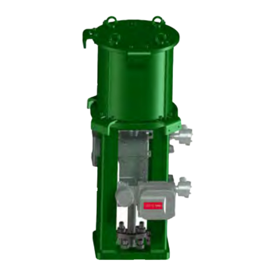
Figure 1. Fisher 785C Single-Acting Spring Return
with Handpump
1
1
3
3
3
3
7
9
9
9
10
12
22
23
23
24
25
27
28
30
32
35
36
36
47
X1851
50
785C Actuator
May 2022
Advertisement
Table of Contents

Related Manuals for Emerson Fisher 785C


Summary of Contents for Emerson Fisher 785C
-
Page 1: Table Of Contents
......Introduction Scope of Manual This instruction manual includes installation, maintenance, and parts information for the Fisher 785C piston actuator. Refer to separate instruction manuals for information regarding other equipment and accessories used with these actuators. - Page 2 1. The pressure/temperature limits in this bulletin and any other applicable standard or code should not be exceeded. 2. Consult your Emerson sales office for longer travels or larger cylinder diameters. The Fisher 585C family of actuators can be used for smaller travels or cylinder diameters.
-
Page 3: Description
Specifications for the 785C line of piston actuators are shown in tables 1 to 8. Refer to the nameplate affixed to the actuator yoke for specifications specific to individual constructions. Educational Services Emerson Automation Solutions Educational Services - Registration Phone: 1-800-338-8158 E-mail: education@emerson.com... - Page 4 3685 3657 1. Consult your Emerson sales office for additional sizes. 2. Actuator size 280-385 are available with a top mounted handwheel. Size 435-685 are available with a side mounted manual handpump. 3. High Performance Yoke required for ODV packages with travel greater than 8 inches. Optional for use in high vibration or fast stroke package. When ordering a high performance yoke boss you will need to order a high performance mounting kit as well.
- Page 5 3657 566.8 1. Consult your Emerson sales office for additional sizes. 2. Actuator size 335-385 are available with a top mounted handwheel. Size 435-685 are available with a side mounted manual handpump. Table 5. 785C Double-Acting Spring Return Standard Constructions...
- Page 6 3657 566.8 3657 566.8 1. Consult your Emerson sales office for additional sizes. 2. Actuator size 280-385 are available with a top mounted handwheel. Size 435-685 are available with a manual handpump. Table 6. Handwheel Specification MAXIMUM RIM OUTPUT THRUST...
-
Page 7: Installation
Instruction Manual 785C Actuator D104483X012 May 2022 Figure 2. Lifting Angle SPRING RETURN ACTUATOR 785C ACTUATOR CENTERLINE HORIZONTAL LIFT VERTICAL HORIZONTAL LIFT Installation Key numbers in this procedure are shown in figures 9 to 28, unless otherwise indicated. WARNING To avoid personal injury or property damage caused by cylinder fracture as a result of piston impact, install the stem connector securely before supplying pressure to the positioner. - Page 8 Actuator Earth Grounding All Fisher 785C series actuators are provided with a threaded actuator earth grounding interface on the yoke (spool) for the earth connection as shown in the figure 3.
-
Page 9: Actuator Earth Grounding
Instruction Manual 785C Actuator D104483X012 May 2022 Figure 3. Actuator Earth Grounding Interface ACTUATOR EARTH GROUND INTERFACE Three‐Way Valve Applications Note In three-way valve applications where the actuator fully strokes at a frequency of once per minute or faster, and the stroking speed is rapid (less than 0.5 seconds per stroke), there is a possibility that the stem can fracture at the plug if the actuator cylinder pressure is greater than 5.5 bar (80 psig). -
Page 10: Handwheel Operation
Instruction Manual 785C Actuator May 2022 D104483X012 Manual Handwheel Operation If manual operation is required for actuator sizes 280, 335, and 385 a manual handwheel should be equipped as standard construction. NOTICE To avoid damage to actuator parts and difficult operation of actuator handwheels, open the bypass valve before using a handwheel. - Page 11 Instruction Manual 785C Actuator D104483X012 May 2022 The following steps reference figure 5 and 6. Refer to table 6 for handwheel specifications. Figure 6. Top Mounted Manual Handwheel Figure 5. Top Mounted Manual Handwheel Engagement/Disengagement Instruction Label HANDLE ENGAGED TO OPEN INSTRUCTION HANDWHEEL WARNING...
-
Page 12: Manual Hydraulic Handpump Operation
The manual handpump control unit must be installed in vertical up direction per figure 7. For application requiring actuator horizontal installation, a special design handpump support and hydraulic tubing must be used to install handpump in vertical up direction per figure 7. Contact your Emerson sales office for further information of manual handpump for actuator horizontal installation Figure 7. - Page 13 Instruction Manual 785C Actuator D104483X012 May 2022 4. Once manual operation is completed, rotate the handle to the “REMOTE” position, as indicated on the instruction plate in figure 8, to disengage the manual operator. Follow figure 11 through 17 handpump schematic detail instructions to allow the “REMOTE “operation with the pneumatic supply.
- Page 14 Instruction Manual 785C Actuator May 2022 D104483X012 Figure 10. Manual Hydraulic Handpump Typical Constructions (Design Varies for Different Actuator Type and Handpump Type) STOP VALVE FOR FAST STROKE TYPE MHQ HANDPUMP HANDLE STOP VALVE (MULTIPLE POSITIONS SHOWING) Table 9. Handpump Schematics Actuator Type Handpump Type Schematics Figure...
- Page 15 Instruction Manual 785C Actuator D104483X012 May 2022 Figure 11. Handpump Schematic: Fast Stroke MHQ Handpump for 785C Spring Return Rod Extend (Fail Down), Single- or Double-Acting PNEUMATIC SUPPLY PNEUMATIC REMOTE CONTROL TO OPEN PRESSURIZED PERMANENTLY THE PNEUMATIC SUPPLY LINE. PNEUMATIC REMOTE CONTROL TO CLOSE DE-PRESSURIZED THE PNEUMATIC SUPPLY LINE.
- Page 16 Instruction Manual 785C Actuator May 2022 D104483X012 Figure 12. Handpump Schematic: Standard Stroke MHP Handpump for 785C Spring Return Rod Extend (Fail Down), Single- or Double-Acting PNEUMATIC SUPPLY PNEUMATIC REMOTE CONTROL TO OPEN PRESSURIZED PERMANENTLY THE PNEUMATIC SUPPLY LINE. PNEUMATIC REMOTE CONTROL TO CLOSE DE-PRESSURIZED THE PNEUMATIC SUPPLY LINE.
- Page 17 Instruction Manual 785C Actuator D104483X012 May 2022 Figure 13. Handpump Schematic: Fast Stroke MHQ Handpump for 785C Spring Return Rod Retract (Fail Up), Single- or Double-Acting PNEUMATIC SUPPLY PNEUMATIC REMOTE CONTROL TO CLOSE PRESSURIZED PERMANENTLY THE PNEUMATIC SUPPLY LINE. PNEUMATIC REMOTE CONTROL TO OPEN DE-PRESSURIZED THE PNEUMATIC SUPPLY LINE.
- Page 18 Instruction Manual 785C Actuator May 2022 D104483X012 Figure 14. Handpump Schematic: Standard Stroke MHP Handpump for 785C Spring Return Rod Retract (Fail Up), Single-or Double-Acting PNEUMATIC SUPPLY PNEUMATIC REMOTE CONTROL TO CLOSE PRESSURIZED PERMANENTLY THE PNEUMATIC SUPPLY LINE. PNEUMATIC REMOTE CONTROL TO OPEN DE-PRESSURIZED THE PNEUMATIC SUPPLY LINE.
- Page 19 Instruction Manual 785C Actuator D104483X012 May 2022 Figure 15. Handpump Schematic: Standard Stroke MHP Handpump for 785C Springless Double-Acting PNEUMATIC SUPPLY TO CLOSE PNEUMATIC SUPPLY TO OPEN PNEUMATIC REMOTE CONTROL TO OPEN PRESSURIZE THE OPENING PNEUMATIC SUPPLY LINE. THE OPENING TIME IS ADJUSTABLE BY THE FLOW REGULATOR 5-Fa. PNEUMATIC REMOTE CONTROL TO CLOSE PRESSURIZE THE OPENING PNEUMATIC SUPPLY LINE.
- Page 20 Instruction Manual 785C Actuator May 2022 D104483X012 Figure 16. Handpump Schematic: Fast Stroke MHQ Handpump Type 1 for 785C Springless Double-Acting PNEUMATIC SUPPLY TO CLOSE PNEUMATIC SUPPLY TO OPEN PNEUMATIC REMOTE CONTROL TO OPEN PRESSURIZE THE OPENING PNEUMATIC SUPPLY LINE. THE OPENING TIME IS ADJUSTABLE BY THE FLOW REGULATOR 5-Fa.
- Page 21 Instruction Manual 785C Actuator D104483X012 May 2022 Figure 17. Handpump Schematic: Fast Stroke MHQ Handpump Type 2 for 785C Springless Double-Acting PNEUMATIC SUPPLY TO CLOSE PNEUMATIC SUPPLY TO OPEN PNEUMATIC REMOTE CONTROL TO OPEN PRESSURIZE THE OPENING PNEUMATIC SUPPLY LINE. THE OPENING TIME IS ADJUSTABLE BY THE FLOW REGULATOR 5-Fa.
-
Page 22: Actuator Mounting
Instruction Manual 785C Actuator May 2022 D104483X012 Actuator Mounting The following procedure describes how to mount a 785C actuator on a push down to close valve so that the piston rod to valve plug stem connection allows full travel and proper shutoff. Key numbers referenced in the following steps are shown in figures 24 through 38 and 48. -
Page 23: Maintenance
Instruction Manual 785C Actuator D104483X012 May 2022 Maintenance Actuator parts are subject to normal wear and must be inspected and replaced when necessary. The frequency of inspection and replacement depends on the severity of service conditions. WARNING Avoid personal injury and property damage from sudden release of process pressure or bursting of parts. Before performing any maintenance operations: D Do not remove the actuator from the valve while the valve is still pressurized. -
Page 24: Disassembling The Pneumatic Cylinder
Instruction Manual 785C Actuator May 2022 D104483X012 3. Remove the bonnet-to-actuator bolting securing the actuator to the bonnet. Make sure the actuator is supported and secured by other means prior to loosening nuts. 4. Using the lifting points provided (key 2215), hoist the actuator vertically taking care not to contact the stem in a manner that would cause damage. -
Page 25: Replacing The Pneumatic Cylinder Seals
Instruction Manual 785C Actuator D104483X012 May 2022 Figure 19. 785C Actuator Pneumatic Cylinder Components Disassembly Sequence Replacing the Pneumatic Cylinder Seals When the pneumatic cylinder is totally disassembled, all the seals can be replaced referencing figures 18, 34, 35, and 36. - Page 26 Instruction Manual 785C Actuator May 2022 D104483X012 Figure 20. Typical Sectional View of 785C Spring Return Actuator Pneumatic Cylinder Seals 2204 2208 2207 2204 2106 2202 2102 2107 NOTE: KEY 2222 PART NOT SHOWN (ACTUATOR WITH HANDPUMP ONLY) Figure 21. Threaded Holes in Pneumatic Cylinder THREAD HOLE THREAD HOLE...
-
Page 27: Assembling The Pneumatic Cylinder
Instruction Manual 785C Actuator D104483X012 May 2022 Assembling the Pneumatic Cylinder The cylinder is reassembled by following in reverse order the sequence described in section Disassembling the Pneumatic Cylinder. The screws must be tightened properly. Refer to table 10. If only a partial replacement of the pneumatic cylinder seals has been performed, the pneumatic cylinder assembly procedure starts from step 3. -
Page 28: Lubrication
M20 x 2.5 M24 x 3 M27 x 3 1. For other bolting materials or lubricants contact your Emerson sales office for torque information. Lubrication The type of grease used and recommended for lubrication purposes at normal operating temperature, is described in table 11. - Page 29 Instruction Manual 785C Actuator D104483X012 May 2022 5. Reinstall and tighten the dipstick. To replace or add oil, proceeding as follow: 1. Remove the dipstick (key 2751-1.7) from the tank cover (key 2751-22). 2. To drain oil, unscrew the plug (key 2751-27) and remove the washer (key 2751-9). Note If dirt and/or sludge is found in the oil drained from the tank, before filling with new oil in the tank, disassemble the oil tank tube by unscrewing the two cap nuts (key 2751-2) and clean the internal surfaces of the tank.
-
Page 30: Disassembling The Handpump Hydraulic Cylinder
Instruction Manual 785C Actuator May 2022 D104483X012 Disassembling the Handpump Hydraulic Cylinder WARNING Refer to the WARNING at the beginning of the Maintenance section in this instruction manual. If there are leaks in the 785C Actuator manual handpump hydraulic cylinder, a malfunction in the mechanical components, or in case of scheduled preventive maintenance, the actuator must be disassembled, and the seals must be replaced with reference to the sectional drawings and following procedures: 1. - Page 31 Instruction Manual 785C Actuator D104483X012 May 2022 2. Assemble the head flange and tighten the screws (key 2621) to the recommended torque (see table 10). 3. Clean and lubricate the piston rod (key 2706) surface, particularly that of the bevel, and insert it into the head flange hole, taking care not to damage the PTFE seal ring (key 2705).
-
Page 32: Other Maintenance Specifications
Instruction Manual 785C Actuator May 2022 D104483X012 Other Maintenance Specifications Table 13. Fisher 785C Series Actuator Pneumatic Cylinder Seal Replacement Information NUT / TIE HEAD CYLINDER PISTON ROD TYPE FLANGE FLANGE CYLINDER, TRAVEL MANUAL Height Weight Weight Weight Weight (mm) - Page 33 Instruction Manual 785C Actuator D104483X012 May 2022 Table 13. Fisher 785C Series Actuator Pneumatic Cylinder Seal Replacement Information (continued) NUT / TIE HEAD CYLINDER PISTON ROD TYPE FLANGE FLANGE CYLINDER, TRAVEL MANUAL (mm) OVERRIDE Height Weight Weight Weight Weight Thread...
- Page 34 Instruction Manual 785C Actuator May 2022 D104483X012 Table 13. Fisher 785C Series Actuator Pneumatic Cylinder Seal Replacement Information (continued) NUT / TIE HEAD CYLINDER PISTON ROD TYPE FLANGE FLANGE CYLINDER, TRAVEL MANUAL (mm) OVERRIDE Height Weight Weight Weight Weight Thread...
-
Page 35: Troubleshooting
11, 13, 16, or 17 Flow restriction in hand pump or hydraulic system Contact your Emerson sales office to upgrade to 785C affecting actuator stroking speed Fast Stroke MHQ handpump type 1 or type 2 Flow restriction in pneumatic system affecting... -
Page 36: Parts Ordering
Parts List. WARNING Use only genuine Fisher replacement parts. Components that are not supplied by Emerson should not, under any circumstances, be used in any Fisher valve, because they may void your warranty, might adversely affect the performance of the valve, and could cause personal injury and property damage. - Page 37 Instruction Manual 785C Actuator D104483X012 May 2022 Table 16. 785C Single-Acting Spring Return (Spring Extend, Fail Down) Spare Parts Kits MATERIAL Flurosilicone CYLINDER SIZE MAXIMUM TRAVEL, INCHES SPRING (Standard Temperature) (Low Temperature) Parts Kit Number R785X335C22 R785X335C42 R785X385C22 R785X385C42 R785X435C22 R785X435C52 R785X485C12 R785X485C32...
- Page 38 Instruction Manual 785C Actuator May 2022 D104483X012 Table 17. 785C Double-Acting Spring Return (Spring Retract, Fail Up) Spare Part Kits MATERIAL MAXIMUM TRAVEL, SPRING Flurosilicone CYLINDER SIZE SPRING INCHES PRELOAD CODE (Standard Temperature) (Low Temperature) Parts Kit Number R785X280C32 R785X280C62 R785X280C42 R785X280C72 R785X335C12...
- Page 39 Instruction Manual 785C Actuator D104483X012 May 2022 Table 17. 785C Double-Acting Spring Return (Spring Retract, Fail Up) Spare Part Kits (continued) MATERIAL Flurosilicone MAXIMUM TRAVEL, SPRING CYLINDER SIZE SPRING INCHES PRELOAD CODE (Standard Temperature) (Low Temperature) Parts Kit Number R785X435C32 R785X435C62 R785X485C12 R785X485C32...
- Page 40 Instruction Manual 785C Actuator May 2022 D104483X012 Table 18. 785C Double-Acting Spring Return (Spring Extend, Fail Down) Spare Part Kits (continued) MATERIAL Flurosilicone MAXIMUM TRAVEL, SPRING CYLINDER SIZE SPRING INCHES PRELOAD CODE (Standard Temperature) (Low Temperature) Parts Kit Number R785X280C32 R785X280C62 R785X280C42 R785X280C72...
- Page 41 Instruction Manual 785C Actuator D104483X012 May 2022 Table 18. 785C Double-Acting Spring Return (Spring Extend, Fail Down) Spare Part Kits (continued) MATERIAL Flurosilicone MAXIMUM TRAVEL, SPRING CYLINDER SIZE SPRING INCHES PRELOAD CODE (Standard Temperature) (Low Temperature) Parts Kit Number R785X385C12 R785X385C32 R785X385C22 R785X385C42...
- Page 42 Instruction Manual 785C Actuator May 2022 D104483X012 Table 19. 785C Double-Acting Springless Spare Part Kits MATERIAL Flurosilicone CYLINDER SIZE MAXIMUM TRAVEL, INCHES (Standard Temperature) (Low Temperature) Parts Kit Number R785X280C12 R785X280C22 R785X335C52 R785X335C62 R785X385C52 R785X385C62 R785X435C72 R785X435C82 R785X485C52 R785X485C62 4, 8, 12, 16, 20, 24 R785X535C52 R785X535C62 R785X585C52...
- Page 43 Instruction Manual 785C Actuator D104483X012 May 2022 Table 21. 785C Spring Return Actuators with Manual Override Spare Parts Kit (continued) MATERIAL MAXIMUM MAXIMUM MANUAL Flurosilicone CYLINDER SIZE SPRING TRAVEL, INCHES PRELOAD OVERRIDE (Standard Temperature) (Low Temperature) Parts Kit Number Hand Wheel R785X335M42 R785X335M12 Hand Wheel...
- Page 44 Instruction Manual 785C Actuator May 2022 D104483X012 Table 21. 785C Spring Return Actuators with Manual Override Spare Parts Kit (continued) MATERIAL Flurosilicone MAXIMUM MAXIMUM MANUAL CYLINDER SIZE SPRING TRAVEL, INCHES PRELOAD OVERRIDE (Standard Temperature) (Low Temperature) Parts Kit Number Hand Pump R785X435M42 R785X435M12 Hand Pump...
- Page 45 Instruction Manual 785C Actuator D104483X012 May 2022 Table 21. 785C Spring Return Actuators with Manual Override Spare Parts Kit (continued) MATERIAL Flurosilicone MAXIMUM MAXIMUM MANUAL CYLINDER SIZE SPRING TRAVEL, INCHES PRELOAD OVERRIDE (Standard Temperature) (Low Temperature) Parts Kit Number Hand Pump R785X535M52 R785X535M22 Hand Pump...
- Page 46 Instruction Manual 785C Actuator May 2022 D104483X012 Table 21. 785C Spring Return Actuators with Manual Override Spare Parts Kit (continued) MATERIAL Flurosilicone MAXIMUM MAXIMUM MANUAL CYLINDER SIZE SPRING TRAVEL, INCHES PRELOAD OVERRIDE (Standard Temperature) (Low Temperature) Parts Kit Number Hand Pump R785X635M82 R785X635M42 Hand Pump...
-
Page 47: Parts List
Parts List 2200 Pneumatic Cylinder Assembly (figure 34, 35, and 36) Description 2201 Head Flange Note 2202* O-Ring Contact your Emerson sales office for Part Ordering information. 2203 Bushing 2204* O-Ring 2205 Washer 2206 Piston 2207* Guide Sliding Ring, Piston Description... - Page 48 Instruction Manual 785C Actuator D104483X012 May 2022 Description Description 2601-10 Plug 2601-11 Thrust Block Ring Nut 2751-1.5 Relief Valve Low 2601-12 Jack Screw 2751-1.6 Relief Valve High 2601-13 Protection Pipe 2751-1.7 Oil Tank Dipstick 2601-14 Spring 2751-2 Cap Nut 2501-15 Kit Cams &...
- Page 49 Instruction Manual 785C Actuator D104483X012 May 2022 Description Description 27H7 90° Elbows Fitting Unions Connector 2752 Handpump 27H8 90° Elbows Fitting Unions Connector 2752-1 Ball 27H9 Adapter Pipe Fitting 2752-2 Delivery Valve Bush 2752-3 Suction Valve Bush 2786U Power Up Tube 2752-4 Spring 2786D Power Down Tube...
-
Page 50: Assembly Drawings
Instruction Manual 785C Actuator May 2022 D104483X012 Assembly Drawings Figure 24. Fisher 785C Double-Acting Springless Actuator with Top Mounted Handwheel ITEMS 4/5/6 MIGHT BE USED FOR VARIOUS APPLICATIONS ITEMS 4/5/6 MIGHT BE USED FOR VARIOUS APPLICATIONS ITEMS 4/5/6 NOT TO SCALE... - Page 51 Instruction Manual 785C Actuator D104483X012 May 2022 Figure 25. Fisher 785C Double-Acting Springless Actuator with Top Mounted Handwheel GH01816_B...
- Page 52 Instruction Manual 785C Actuator May 2022 D104483X012 Figure 26. Fisher 785C Double-Acting Springless Actuator with Side Mounted Handpump ITEMS 4/5/6 MIGHT BE USED FOR VARIOUS APPLICATIONS ITEMS 4/5/6 MIGHT BE USED FOR VARIOUS APPLICATIONS ** COMPONENT INCLUDES RECOMMENDED SPARE PART...
- Page 53 Instruction Manual 785C Actuator D104483X012 May 2022 Figure 27. Fisher 785C Double-Acting Springless Actuator with Side Mounted Handpump GH01791_B...
- Page 54 Instruction Manual 785C Actuator May 2022 D104483X012 Figure 28. Fisher 785C Single-Acting Spring Return Actuator without Manual Override ITEMS 4/5/6 MIGHT BE USED FOR VARIOUS APPLICATIONS ITEMS 4/5/6 MIGHT BE USED FOR VARIOUS APPLICATIONS ITEMS 4/5/6 NOT TO SCALE ** COMPONENT INCLUDES RECOMMENDED SPARE PART...
- Page 55 Instruction Manual 785C Actuator D104483X012 May 2022 Figure 29. Fisher 785C Single-Acting Spring Return Actuator without Manual Override GH01864_B...
- Page 56 Instruction Manual 785C Actuator May 2022 D104483X012 Figure 30. Fisher 785C Spring Return Assembly with Side Mounted Handpump, Rod Extend ITEMS 4/5/6/12 MIGHT BE USED FOR VARIOUS APPLICATIONS ITEMS 4/5/6 MIGHT BE USED FOR VARIOUS APPLICATIONS ITEMS 4/5/6 ARE NOT TO SCALE...
- Page 57 ITEMS 4/12 ARE NOT TO SCALE ** COMPONENT INCLUDES RECOMMENDED SPARE PART PARTS NOT SHOWN: KEY 400, 500 GH14253 Figure 33. Fisher 785C Springless Assembly with Fast Stroke Side Mounted Handpump MHQ ITEMS 4/12 MIGHT BE USED FOR VARIOUS APPLICATIONS...
- Page 58 Instruction Manual 785C Actuator May 2022 D104483X012 Figure 34. Pneumatic Cylinder Assembly of Fisher 785C Actuator without Manual Override, Springless or Spring Return, Single- or Double-Acting * COMPONENT INCLUDES RECOMMENDED SPARE PART ** ITEM NOT REQUIRED FOR THIS ASSEMBLY GH01624_B...
- Page 59 Instruction Manual 785C Actuator D104483X012 May 2022 Figure 35. Pneumatic Cylinder Assembly of Fisher 785C Actuator with Top Mounted Handwheel, Springless or Spring Return, Single- or Double-Acting * COMPONENT INCLUDES RECOMMENDED SPARE PART ** ITEM NOT REQUIRED FOR THIS ASSEMBLY...
- Page 60 Figure 36. Pneumatic Cylinder Assembly of Fisher 785C Actuator with Side Mounted Handpump, Springless or Spring Return, Single- or Double-Acting * COMPONENT INCLUDES RECOMMENDED SPARE PART GH01644_A Figure 37. Yoke (Spool) Assembly of Fisher 785C Actuator Springless or Spring Return, Single- or Double-Acting GH01609_A...
- Page 61 Instruction Manual 785C Actuator D104483X012 May 2022 Figure 38. Spring Can (Spring Cartridge) Fisher 785C Single-Acting Spring Return Actuator Single- or Double-Acting SECTION B-B SECTION A-A GH01764_A...
- Page 62 Instruction Manual 785C Actuator May 2022 D104483X012 Figure 39. Top Mounted Handwheel of Fisher 785C Actuator, Springless or Spring Return, Single- or Double-Acting * COMPONENT INCLUDES RECOMMENDED SPARE PART PARTS NOT SHOWN: 2609 GH01762_B Figure 40. Handwheel MHW Unit (Key 2601)
- Page 63 Instruction Manual 785C Actuator D104483X012 May 2022 Figure 41. Side Mounted Handpump Hydraulic Cylinder Assembly of Fisher 785C Actuator Springless or Spring Return, Single- or Double-Acting DETAIL B DETAIL C SECTION B-B SECTION A-A SCALE 1:1 DETAIL C GH01653_A...
- Page 64 Instruction Manual 785C Actuator May 2022 D104483X012 Figure 42. Side Mounted Handpump Support of Fisher 785C Actuator Springless or Spring Return, Single- or Double-Acting GH01747_A...
- Page 65 Instruction Manual 785C Actuator D104483X012 May 2022 Figure 43. MHP Hydraulic Fittings GH14070 GH14490...
- Page 66 Instruction Manual 785C Actuator May 2022 D104483X012 Figure 44. MHQ Hydraulic Fitting, Tubes and Stop Valve GH14073...
- Page 67 Instruction Manual 785C Actuator D104483X012 May 2022 Figure 45. Side Mounted Handpump Hydraulic Control Unit of Fisher 785C Actuator Springless or Spring Return, Single- or Double-Acting * COMPONENT INCLUDES RECOMMENDED SPARE PART PARTS NOT SHOWN: 2759 GH0172_9...
- Page 68 Instruction Manual 785C Actuator May 2022 D104483X012 Figure 46. Handpump MHP/MHQ Hydraulic Control Unit (Key 2751) OIL TANK RELIEF VALVE RELIEF VALVE OIL TANK DIPSTICK RELIEF VALVE FOR AUTOMATIC OPERATION CHECK VALVE FLOW REGULATOR RELIEF VALVE FOR MANUAL OPERATION **RECOMMENDED SPARE PART GH14297...
- Page 69 Instruction Manual 785C Actuator D104483X012 May 2022 Figure 47. MHP/MHQ Handpump (Key 2752) **RECOMMENDED SPARE PART GH14482...
- Page 70 Instruction Manual 785C Actuator May 2022 D104483X012 Figure 48. Valve Stem Connector Assembly of Fisher 785C Actuator Springless or Spring Return, Single- or Double-Acting GH01638_A Figure 49. Mounting Bracket Assembly of Fisher 785C Actuator Springless or Spring Return, Single- or Double-Acting...
- Page 71 Instruction Manual 785C Actuator D104483X012 May 2022 Figure 50. Nameplate Assembly Kit of Fisher 785C Figure 52. Fisher 785C Springless Actuator Repair Actuator Springless or Spring Return, Single- or Kit, Double-Acting Double-Acting * COMPONENT INCLUDES RECOMMENDED SPARE PART GH01657_A GH01593_A Figure 51.
- Page 72 Responsibility for proper selection, use, and maintenance of any product remains solely with the purchaser and end user. Fisher, FIELDVUE, and easy-e are marks owned by one of the companies in the Emerson Automation Solutions business unit of Emerson Electric Co. Emerson Automation Solutions, Emerson, and the Emerson logo are trademarks and service marks of Emerson Electric Co.
Need help?
Do you have a question about the Fisher 785C and is the answer not in the manual?
Questions and answers