Table of Contents
Advertisement
Change for life
Service Manual
Models:
JKFD5DQS/Na-E、JKFD5DC/Na-E
JKFD7DQS/Na-E、JKFD7DC/Na-E
JKFD7QS/Na-M、JKFD7C/Na-M
JKFD13QS/Na-M、JKFD13C/Na-M、JKFD13SX/Na-M
JKFD19QS/Na-M、JKFD19C/Na-M、JKFD19SX/Na-M
JKFD25QS2/Na-M、 JKFD25C2/Na-M、 JKFD25SX2/Na-M
JKFD40QS2/Na-M、 JKFD40C2/Na-M、 JKFD40SX2/Na-M
JKFD40QS/Na-M、JKFD40C/Na-M
(Refrigerant R410A)
GREE ELECTRIC APPLIANCES,INC.OF ZHUHAI
ТОО "Everest climate", Р. К., г.Алматы | Телефон: +7 727 230 00 10, +7 777 250 10 90 | www.aircon.kz, e-mail: info@aircon.kz
Advertisement
Table of Contents

Subscribe to Our Youtube Channel
Related Manuals for Gree JKFD5DQS/Na-E


Summary of Contents for Gree JKFD5DQS/Na-E
- Page 1 JKFD5DQS/Na-E、JKFD5DC/Na-E JKFD7DQS/Na-E、JKFD7DC/Na-E JKFD7QS/Na-M、JKFD7C/Na-M JKFD13QS/Na-M、JKFD13C/Na-M、JKFD13SX/Na-M JKFD19QS/Na-M、JKFD19C/Na-M、JKFD19SX/Na-M JKFD25QS2/Na-M、 JKFD25C2/Na-M、 JKFD25SX2/Na-M JKFD40QS2/Na-M、 JKFD40C2/Na-M、 JKFD40SX2/Na-M JKFD40QS/Na-M、JKFD40C/Na-M (Refrigerant R410A) GREE ELECTRIC APPLIANCES,INC.OF ZHUHAI ТОО "Everest climate", Р. К., г.Алматы | Телефон: +7 727 230 00 10, +7 777 250 10 90 | www.aircon.kz, e-mail: info@aircon.kz...
-
Page 2: Table Of Contents
Table of Contents ⅠProduct ......................1 Naming Convention of Products ....................2 2. Features of Product ........................3 3. System Principle ..........................5 3.1 Flowchart of the System ....................5 3.2 Description of the System ....................5 4. Performance Parameters ......................... 6 5. - Page 3 4.7 User and role management ........Ошибка! Закладка не определена. 4.8 Others ..............Ошибка! Закладка не определена. Ⅲ Maintenance ........Ошибка! Закладка не определена. Malfunction List .............. Ошибка! Закладка не определена. 2. Troubleshooting ..............Ошибка! Закладка не определена. 2.1 High Pressure Protection of Compressor ... Ошибка! Закладка не определена. 2.2 Low Pressure Protection of Compressor ...
-
Page 4: Ⅰproduct
GREE Air-ccoled Closed Control Unit Service Manual ⅠProduct Indoor Unit Outdoor Unit ТОО "Everest climate", Р. К., г.Алматы | Телефон: +7 727 230 00 10, +7 777 250 10 90 | www.aircon.kz, e-mail: info@aircon.kz... -
Page 5: Naming Convention Of Products
GREE Air-ccoled Closed Control Unit Service Manual 1. Naming Convention of Products □ □ □ □ Description Option Product JK-Closed Control Air Conditioner Classification Cooling Down Omitted—Water-cooled Packaged Unit Method and F—Air-cooled Split Unit Structure Y—Ethylene Glycol-cooled Split Unit Omitted—Cooling Only Unit D—Cooling Only Unit +Electric Heater+... -
Page 6: Features Of Product
GREE Air-ccoled Closed Control Unit Service Manual 2. Features of Product Gree JKF Series Air-cooled Closed Control Unit is specially designed for the room where communication equipment, computer, and precise instruments are placed. Applying components with high performance, wide and touchable screen, advanced system design as well as powerful control logic, the unit can efficiently control ambient humidity and keep stable and long-term operation. - Page 7 ◆ Multi products Wide cooling range: GREE JKF series air-cooled closed control units include 5kW, 7kW, 13kW, 19kW, 25kW and 40kW units. And also, with combination of modules, customers can easily select proper units according to their demand.
-
Page 8: System Principle
GREE Air-ccoled Closed Control Unit Service Manual 3. System Principle 3.1 Flowchart of the System Fan Motor Condensate Fan Humidifier Electric Heater Condenser Diverter Evaporator Expansion Valve Solenoid Valve Compressor 3.2 Description of the System Structural features and system layout of JKF Series Air-cooled Closed Control Air Conditioner are illustrated as above. -
Page 9: Performance Parameters
GREE Air-ccoled Closed Control Unit Service Manual 4. Performance Parameters Form 1 Model Class Item JKFD5DC/Na-E JKFD5DQS/Na-E Unit Code of Product EJ13000380 EJ13000250 Total Cooling Capacity / Sensible 5.0/4.5 Cooling Capacity(22℃/50%) Total Cooling Capacity / Sensible 5.3/4.8 Cooling Capacity(24℃/17℃) Total Cooling Capacity / Sensible 5.2/4.7... - Page 10 GREE Air-ccoled Closed Control Unit Service Manual Type Low Noise Axial Type Condensing Type of Drive Direct Drive Noise dB(A) Dimension 1000 Net Weight mm×pcs Φ9.52×1 Liquid Refrigerant Connection Pipe Gas Refrigerant Pipe mm×pcs Φ12×1 pipe Method of Connection Flared-fitting Joint...
- Page 11 GREE Air-ccoled Closed Control Unit Service Manual Dimension 2250 1950 Net Weight JKFD7/Na-E(O) Outdoor Unit Model Type Low Noise Axial Type Condensing Type of Drive Direct Drive Outdoor Noise dB(A) Unit Dimension 1000 Net Weight Φ9.52×1 Liquid Refrigerant Pipe mm×pcs Connectio Φ12×1...
- Page 12 GREE Air-ccoled Closed Control Unit Service Manual Type Electrode Type Humidifyi Humidifier System Automatic Control by Mainboard Control Mode Indoor Unit Model JKFD7C/Na-M(I) JKFD7QS/Na-M(I) Indoor Unit Dimension 2250 1950 Net Weight JKFD7/Na-M(O) Outdoor Unit Model Type Low Noise Axial Type...
- Page 13 GREE Air-ccoled Closed Control Unit Service Manual Type Low Noise and Centrifugal External-rotor Type of Supply Indoor Unit Direct Drive System Drive Air Filter Type Plate Filter (G4) Heating Heater Type Electric Heating System Humidifyi Electrode Type Type Humidifier System...
- Page 14 GREE Air-ccoled Closed Control Unit Service Manual Condenser Type Inner Screw Thread Pipe with Hydrophilic Film Aluminum Fin Refrigerant R410A Throttling Method Electronic Expansion Valve Type Low Noise and Centrifugal External-rotor Type of Supply Indoor Unit Direct Drive System Drive...
- Page 15 GREE Air-ccoled Closed Control Unit Service Manual Compressor Type Hermetic Scroll Type Evaporator Type Inner Screw Thread Pipe with Hydrophilic Film Aluminum Fin Cooling Condenser Type Inner Screw Thread Pipe with Hydrophilic Film Aluminum Fin System Refrigerant R410A Throttling Method...
- Page 16 GREE Air-ccoled Closed Control Unit Service Manual Rated Humidifying kg/h Capacity Air Flow Volume 13000 12500 12500 External Static Pressure Acoustic Noise of dB(A) Indoor Units Range of Temp. Controlling and 17~28℃±1℃ Precision Range of Humidity and Precision 40~60%±5% Power Supply 380V 3N~...
- Page 17 GREE Air-ccoled Closed Control Unit Service Manual Total Cooling Capacity / Sensible 39.4/36.0 Cooling Capacity(22 ℃/50%) Total Cooling Capacity / Sensible 40.0/36.1 Cooling Capacity(24 ℃/17℃) Total Cooling Capacity / Sensible 39.2/37.5 Cooling Capacity(24 ℃/45%) Total Cooling Capacity / Sensible 42.5/38.0...
-
Page 18: Rformance Correctlon
GREE Air-ccoled Closed Control Unit Service Manual Indoor Unit Model JKFD40C/Na-M(I) JKFD40QS/Na-M(I) 2480 2480 Indoor Unit Dimension 2250 1950 Net Weight Outdoor Unit Model JKFD40/Na-M(O) Type Low Noise Axial Type Condensing Type of Drive Direct Drive Outdoor Unit Noise dB(A) - Page 19 GREE Air-ccoled Closed Control Unit Service Manual JKFD7XXX Cooling capacity correction for single-phase unit JKFD5XXX Cooling capacity correction for single-phase unit 28(50%) 28(50%) 26(50%) 26(50%) 24(45%) 23(17℃) 23(17℃) 24(45%) 22(50%) 22(50%) 20(50%) 18(50%) 20(50%) 17(50%) 18(50%) 17(50%) OUD air inlet dry-bulb temperature( ℃)...
-
Page 20: Coefficient Of Correction Table For Various Conditions Of Installation
GREE Air-ccoled Closed Control Unit Service Manual JKFD40XXX Cooling capacity correction for three-phase unit 28(50%) 26(50%) 23(17℃) 22(50%) 24(45%) 20(50%) 18(50%) 17(50%) OUD air inlet dry-bulb temperature( ℃) 5.2 Coefficient of Correction Table for Various Conditions of Installation The cooling capacity can be affected by the long connecting pipe, as well as the high drop between outdoor and indoor units. - Page 21 GREE Air-ccoled Closed Control Unit Service Manual the relative equivalent length of elbow and oil loop Outside Diameter of Connecting Pipe(mm) Oil Loop (m) Elbow Ф9.52 Ф12 0.25 Ф16 Ф19 0.35 Ф22 Note: The equivalent pipe length equals the length of straight pipe plus the equivalent length of elbow and oil loop.
-
Page 22: Installation Of The Unit
GREE Air-ccoled Closed Control Unit Service Manual 6. Installation of the unit 6.1 Installation Diagram of the Complete Unit The complete unit consists of outdoor unit and indoor unit, which is shown as below: 6.2 Outline Dimension of the Unit 6.2.1 Indoor Unit... - Page 23 GREE Air-ccoled Closed Control Unit Service Manual Right Side Back Side Front Side ◆ Outline Dimension of Indoor Units of JKFD13 Series (Direct Air Supply) Right Side Front Side Back Side ТОО "Everest climate", Р. К., г.Алматы | Телефон: +7 727 230 00 10, +7 777 250 10 90 | www.aircon.kz, e-mail: info@aircon.kz...
- Page 24 GREE Air-ccoled Closed Control Unit Service Manual ◆Outline Dimension of Indoor Units of JKFD13 Series (Top Air Outlet) Right Side Front Side Back Side ◆Outline Dimension of Indoor Units of JKFD13 Series (Bottom Air Outlet) Right Side Front Side Back Side...
- Page 25 GREE Air-ccoled Closed Control Unit Service Manual ◆Outline Dimension of Indoor Units of JKFD19 Series (Direct Air Supply) Right Side Front Side Back Side ◆Outline Dimension of Indoor Units of JKFD19 Series (Top Air Outlet) Right Side Front Side Back Side...
- Page 26 GREE Air-ccoled Closed Control Unit Service Manual ◆Outline Dimension of Indoor Units of JKFD19 Series (Bottom Air Outlet) 右侧面 正面 背面 Right Side Front Side Back Side ◆Outline Dimension of Indoor Units of JKFD25 Series (Direct Air Supply) Right Side...
- Page 27 GREE Air-ccoled Closed Control Unit Service Manual ◆Outline Dimension of Indoor Units of JKFD25 Series (Top Air Outlet) Right Side Front Side Back Side ◆Outline Dimension of Indoor Units of JKFD25 Series (Bottom Air Outlet) Right Side Front Side Back Side...
- Page 28 GREE Air-ccoled Closed Control Unit Service Manual ◆Outline Dimension of Indoor Units of JKFD40 Series (Direct Air Supply) Right Side Front Side Back Side 2480 ◆Outline Dimension of Indoor Units of JKFD40 Series (Top Air Outlet) Right Side Front Side...
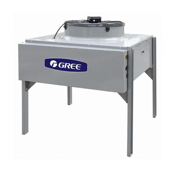
- Page 29 GREE Air-ccoled Closed Control Unit Service Manual ◆Outline Dimension of Indoor Units of JKFD40 Series (Bottom Air Outlet) Right Side Front Side Back Side 2480 6.2.2 Outdoor Unit ◆ Outline Dimensions of JKFD5/Na-E(O)and JKFD7/Na-E(O) (The picture is for a reference only and the actual item is the standard. Unit: mm)
- Page 30 GREE Air-ccoled Closed Control Unit Service Manual ◆ JKFD13/Na-M(O)、JKFD13/NaA-M(O) ◆ JKFD19/Na-M(O)、JKFD19/NaA-M(O) ◆ JKFD40/Na-M(O) ТОО "Everest climate", Р. К., г.Алматы | Телефон: +7 727 230 00 10, +7 777 250 10 90 | www.aircon.kz, e-mail: info@aircon.kz...
-
Page 31: Installation Dimension And Space
GREE Air-ccoled Closed Control Unit Service Manual 6.3 Installation Dimension and Space 6.3.1 The Installation of Indoor Unit ◆Direct Air Supply (with cowl) Ceiling No Special Requirement Wall Face On Distance > > Facade Wall Face Ground ◆ Front Discharge ( connecting duct )... - Page 32 GREE Air-ccoled Closed Control Unit Service Manual the Flange Size of Air Outlet on Top of the unit 正面 Model JKFD5DQS/Na-E (I)、 JKFD7DQS/Na-E(I)、 JKFD7QS/Na-M (I) JKFD13QS/Na-M (I) JKFD19QS/Na-M (I) JKFD25QS2/Na-M (I) 1263 正面 JKFD40QS2/Na-M(I)、JKFD40QS/Na-M(I) ТОО "Everest climate", Р. К., г.Алматы | Телефон: +7 727 230 00 10, +7 777 250 10 90 | www.aircon.kz, e-mail: info@aircon.kz...
- Page 33 GREE Air-ccoled Closed Control Unit Service Manual ◆Top Air Intake and Bottom Air Discharge Ceiling Wall Face Return Air > > Facade Bracket Separator Dischange Air Wall Face Ground 6.3.2 Installation of Outdoor Unit ◆ Disassembly of Outdoor Unit Local Room of...
- Page 34 GREE Air-ccoled Closed Control Unit Service Manual ◆ Mounting Hole on Base Mounting Holes Waist-shaped Hole 12 × 30mm JKFD5/Na-E(O)、JKFD7/Na-E(O) JKFD13/Na-M(O)、JKFD13/NaA-M(O)、JKFD19/Na-M(O)、JKFD19/NaA-M(O) ТОО "Everest climate", Р. К., г.Алматы | Телефон: +7 727 230 00 10, +7 777 250 10 90 | www.aircon.kz, e-mail: info@aircon.kz...
- Page 35 GREE Air-ccoled Closed Control Unit Service Manual JKFD40/Na-M(O) ◆ Installation of Single Unit Obstacle Wall Face Air Outlet > 1000 > 1000 Wall Face Ground Electric Box and The Exit of Tube are On This Side ◆ Parallel Installation of Multi-units >...
-
Page 36: Requirements Of Installation
GREE Air-ccoled Closed Control Unit Service Manual Caution! 1. Intense magnetic field, high saline and alkaline land, the sites of high acid or extreme voltage instability are not suitable for the unit. 2. Make sure that the way of moving in is correct in case any damage to the unit or any danger occurred. - Page 37 GREE Air-ccoled Closed Control Unit Service Manual (8) Make sure that the drainage of condenser water and humidifier are smooth. Due to the possibility of high temperature (maximum temp. could be 100℃) of humidifier’s drain water, shall pay attention to the security of the drainage.
- Page 38 GREE Air-ccoled Closed Control Unit Service Manual Charge volume(kg) Charge volume Item of refrigerants for (kg)of lubricants for Notes every 1 m longer of every 10 m longer of Model connecting pipe connecting pipe JKFD5DXXX 0.054 JKFD7DXXX JKFD7XXX Use R410A JKFD13XXX 0.11...
- Page 39 GREE Air-ccoled Closed Control Unit Service Manual has bad electric conductivity. (6) Do not use hot water, which will produce encrustation and cause blockage to nozzle of the water inlet valve. (7) For the normal running and lengthening life span of humidifier, the water with high electric conductivity (above 700MΩ) has to be preprocessed.
-
Page 40: Electric Installation
GREE Air-ccoled Closed Control Unit Service Manual 7. Electric installation 7.1 Electrical Installation 7.1.1 General Connection Diagram Input Power Switch Residual Current Circuit Breaker Single-phase Single-phase/Three-phase 7.1.2 External Wiring Diagram Power Supply Terminals of The Indoor Unit Input Power Supply... - Page 41 GREE Air-ccoled Closed Control Unit Service Manual Power Supply Terminals of The Indoor Unit Input Power Supply Patchboard Power Supply Terminals of The Outdoor Unit Patchboard Brown Brown Blue Blue Yellow/Green Yellow/Green JKFD7XXX JKFD13XXX JKFD19XXX Power Supply Terminals Input Power Supply...
- Page 42 GREE Air-ccoled Closed Control Unit Service Manual Power Supply Terminals of The Indoor Unit Input Power Patchboard 380V/50Hz Power Supply Terminals of The Outdoor Unit Patchboard Patchboard YEGN JKFD40QS/Na-M (380V 3N~ 50Hz) All Kinds of Warning Wiring Diagram Unit Terminal...
- Page 43 GREE Air-ccoled Closed Control Unit Service Manual 7.1.3 Wiring Requirements ◆ Layout of Electric Wires (1)The layout should comply with relating regulations published and executed by government. (2)Rated Voltage and dedicated power supply of the unit are required to apply.
-
Page 44: Matching Form Of Power Cord And Air Switch
GREE Air-ccoled Closed Control Unit Service Manual following places: ① Water pipe; ② Gas pipe; ③ Blowing pipe; ④Other places that professional personnel consider unreliable. 7.2 Matching Form of Power Cord and Air Switch Minimum Sectional ) Air Switch Area(mm... -
Page 45: Ⅱ Control
GREE Air-ccoled Closed Control Unit Service Manual Ⅱ Control 1 Control of the Unit 1.1 General Control When the unit is energized, the system starts to detect each part. If there is malfunction, malfunction code will be displayed and relevant procedure will be entered. If there is not malfunciton, the unit will operate according to command from display panel. - Page 46 GREE Air-ccoled Closed Control Unit Service Manual Power Recovery Judge malfunction processing Timer on or off process Timer on or not Turning off process Turning off manual Auto/manual Manual process auto Auto control process Malfunction Recovery processing Cut off power Stop ТОО...
-
Page 47: Introduction To Key Control Logic Of The Unit
GREE Air-ccoled Closed Control Unit Service Manual 1.2 Introduction to Key Control Logic of the Unit (1)Control of Indoor Fan When pressing ON button or timer on is reached, the fan will operate in set time. When the unit is turned off or timer off is reached, indoor fan will be turned off in 3 minutes. Indoor fan shall operate earlier than other loads. -
Page 48: Controller
2. Controller This touch screen adopts high-performance processor and window-operation system. The running state of the system is described by text, diagram or curve. All kinds of running parameters can be flexibly set by the unit to optimum state and make the man-machine conversion come true. - Page 49 There is a Function Menu on the right of the screen, which is displayed all the time. It consists of a group of touch buttons to realize the quick access to and control on the air conditioning system. Homepage User Setting Setting Run Status Event Log...
-
Page 50: User Setting Interface
“ON/OFF”: As it is touched, the system will issue a command to change the ON/OFF state. The hint information on the button will accordingly change to the current controlled running state of entire module. If the “ON/OFF” button shows that the current state is OFF and it is touched afterwards, the hint information on the button will change to “ON”... - Page 51 “Module Mode Setting”、“Time Setting”、“Timer Setting.”:Slightly press these buttons to enter the corresponding setting page. “Numeric Value Input”: The numeric value with box represents what can be revised. By touching the number in the box, the keyboard interface is popped up and the number in the touched box displays the blinking cursor which means the number in the input state.
- Page 52 When the touch screen is shielded, “Shield Touch Screen! Invalid Setting!” will be shown on the right side of the interface. In that case, each setting interface is read-only and its parameter setting cannot be revised. (2)Module Mode Setting Slightly press the button “Module Setting” to enter the interface of “Module Mode Setting” Only when unit is set off on the homepage can the mode setting of each module be effective on this interface.
-
Page 53: Running Status Interface
Qty of entire running module units, all units that are qualified to be standby units will stop to be standby and there is no alternative running unit. (3)Time & Date Setting Interface Slightly press the button “Time Setting” to enter the interface of “Time & Date Setting”. It can be revised by touching the corresponding numeric box.
Need help?
Do you have a question about the JKFD5DQS/Na-E and is the answer not in the manual?
Questions and answers