Table of Contents
Advertisement
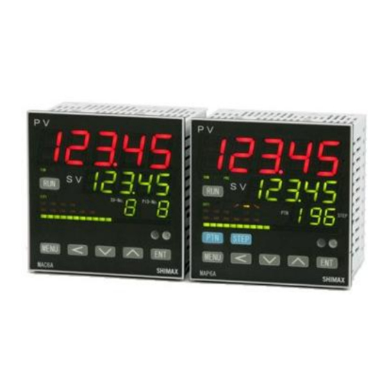
Digital Controller
MAC6A/MAP6A
Instruction manual
Thank you for purchasing SHIMAX products.
Please check that the delivered Item is the item you ordered. Read this instruction manual
thoroughly and understand its contents before using this product.
Please ensure that this manual is given to the final user of this product.
MAP6F-1EE March 2017
Advertisement
Table of Contents

Subscribe to Our Youtube Channel
Related Manuals for Shimax MAC6A


Summary of Contents for Shimax MAC6A
- Page 1 Digital Controller MAC6A/MAP6A Instruction manual Thank you for purchasing SHIMAX products. Please check that the delivered Item is the item you ordered. Read this instruction manual thoroughly and understand its contents before using this product. Please ensure that this manual is given to the final user of this product.
-
Page 2: Table Of Contents
Contents 1. Preface ..................................2 2. Matters regarding safety .............................. 2 3. Introductions ................................4 3-1. Check before use ..............................4 3-2. Order code table ..............................5 4. Installation and Wiring ..............................6 4-1. Installation (Environmental conditions) ........................6 4-2. Mounting ................................6 4-3. -
Page 3: Preface
1. Preface This instruction manual is intended for those who will be involved in wiring, installation, operation and routine maintenance of the MAC6 and MAP6. This manual describes the care, installation, wiring, function, and proper procedures regarding the operation of MAC6 and MAP6. - Page 4 CAUTION ●The mark on the plate affixed to the instrument on the terminal nameplate affixed to the case of your instrument, the mark is printed. This is to warn you of the risk of electrical shock which may result if the charger is touched while it is energized.
-
Page 5: Introductions
3. Introductions 3-1. Check before use Before using MAP6, please check the model code, the exterior appearance and accessories. Also make sure that there are no errors, impairs and shortages. Confirmation of model code Check that the product you ordered is being delivered properly. Check the model code of the main body case against the following code table. -
Page 6: Order Code Table
Code Specifications Series MAP6A- 96 x 96 size 5 digit display programmable digital controller Series MAC6A- 96 x 96 size 5 digit display digital controller Input M Full multi TC, RTD, mV, V, mA ※1 Contact 1a 240V AC 2A (Resistance load) -
Page 7: Installation And Wiring
4. Installation and Wiring 4-1. Installation (Environmental conditions) CAUTION This instrument should not be used in any of the places mentioned below. Selection of these places may result in trouble with the instrument, damage to it or even a fire. ●Where flammable gas, corrosive gas, oil mist and particles generated. -
Page 8: External Dimensions And Panel Cutout
4-3. External Dimensions and Panel Cutout External dimension (Unit: mm) Panel cutout (Unit: mm) Note: Proximity attachment by a single hole is possible only in the case of horizontal direction. When an apparatus that was attached in vertical direction is removed, a dedicated detachment tool is required. - Page 9 4-4. Wiring WARNING ● When wiring, make sure to disconnect the power supply. Otherwise an electric shock may result. ● After wiring, do not touch terminals or other charged elements while it is energized. Otherwise an electric shock may result. ●...
-
Page 10: Terminal Arrangement
4-5. Terminal arrangement Note: If input type is thermocouple or voltage, errors may occur when terminal 11 and terminal 12 terminal are short-circuited... -
Page 11: Terminal Arrangement Table
4-6. Terminal arrangement table Symbol Function Symbol Function Control motor drive output + DI input AO Output - + Voltage(V) or Current DO Output (DO1-3, DO4-6) (mA) Input - + Thermo couple or Voltage(mV) Input - A B Resistance bulb input Feedback potentiometer input b... -
Page 12: Names And Functions Of Parts On Front Panel
5. Names and Functions of Parts on Front Panel MAP6A ① MAC6A ② ④ ③ ⑤ ⑥ ⑧ ⑦... -
Page 13: Explanation Of Each Functions
5-1. Explanation of each functions ①Display of measured value (PV) (red) Measured value (PV) and type of setting is displayed on each setting screen. ②Display of target value (SV) (green) Target value and set value are displayed on each setting screen. ③Pattern No, Display (Green) (PID No, on MAC6)... - Page 14 ⑦Key-switch section (RUN)KEY: Press for 3 seconds at STBY (control stop), then FIX or PROG control starts. Press for 3 seconds while FIX or PROG is in operation, then control is stopped. (MENU)KEY: Press this key to move onto the next screen among the screens. en of FIX or PROG, then it jumps on the screen of operation mode 2, then it jumps to the screen of operation Mode 1.
- Page 15 .1-96 from Program step lead screen. Pattern1 Step1 Pattern1 Step2 Pattern1 Step15 Pattern1 Step96 The setting data changed on each screen is determined. (The decimal point of the minimum digit is also lighted off). Press the key for 3 seconds on the Mode 1 screen, then it shifts to Mode 2 screen. Press three seconds on the monitor screen during RUN operation it shifts between Manual output and automatic output.
-
Page 16: Description Of Screens
6. Description of screens 6-1. How to move to another screen Basic screen Program control lead screen FIX control lead screen 3 sec 3 sec Press the key for three seconds on a basic screen, then it shifts to the lead screen of (program control) setting screens. - Page 17 Press the key on the first setting screen of each screens, then it shifts to the next screen. Every time you press the key, it shifts to the next setting screen.
-
Page 18: Setting Method
6-2. Setting method To change settings, display an appropriate screen and On the output monitor screen of basic screens, you can change the control output from "Automatic" to "manual", and save its change of setting. Display the outp seconds to shift from Automatic to Manual. Press Automatic⇔Manual switchover does not work while STBY<RST>... - Page 19 6-4 Explanation of each basic screen Basic screen Executed SV Initial value Sensor input : 0 Linear input : Lower limit of scaring Setting range Sensor input : Within measuring range Linear input With in scaring range Within SV limiter besides Targeted value (PV) is displayed on the upper row as 5-digit, and target value (SV) is displayed on the lower row also as 5-digit.
- Page 20 Press key for 3 seconds, then it shifts to Action mode2 screen, when the program control option is added on this screen, FIX (constant value control) ←→PROG (program control) switchover is possible choose(Choose a program, then Monitor LED's PRG lights up. Press key for 3seconds then it shift to Action mode 1.
- Page 21 Program step time period Display screen Display Range : 000:00 – 3000:00 or ∞ (infinity) Upper Display: PV value Middle Display: Time remain Lower Display: Pattern No, & Step No, Displays while program is in operation. On-going step № and the remaining repeating time of pattern are displayed A remaining time and an elapsed time is switchable by pressing the key for 3 seconds.
- Page 22 Servo output position monitor screen Display range 0.0 - 100.0 % Servo output position is displayed. This screen is not displayed without Servo output option and feedback input. Hold execution screen While HOLD is executed, on the basic screen, SV value and displayed by turns.
- Page 23 Program pattern No, selection screen Initial value:1 Setting range:1 - 8 The number of setting in the program pattern screen can be changed 1-8 to the number of program pattern. Only the pattern you did program pattern setting screen will be indicated. Not displayed in the state of FIX operation FIX execution SV setting screen Initial Value: 1...
- Page 24 EV 1 lower operating point setting screen The operating point of the alarm type allotted to EV1 is set up. No display when no EV option installed or , and are allotted to EV1. ~ The operation mode of each deviation alarm is Effective at the time of automatic output.
- Page 25 EV1 Lower operating point setting screen Initial value: Minimum value of setting range. Display when EV1 allotted to EV1 Upper operating point setting screen Initial value : Maximum value of setting range Setting range : within measuring range Display when EV1 allotted to EV2 –...
- Page 26 External operation output (DO)Setting screen The operating point of the alarm allotted to DO1 is set up. No display when no DO option installed, ~ are allotted to DO1. The operation mode of each deviation alarm is effective at the time of automatic output.
- Page 27 Latching release screen Initial value: Setting range: 、 、 、 、 、 、 、 、 、 On the latching setting screen of each EV and DO mode, which chose are displayed. If latching is once EV and DO are outputted, output state are maintained even if the state of OFF.
-
Page 28: Prog (Program Control) Setting Screens
6-4. PROG (program control) setting screens Press key for 3 seconds, lead screen of the PROG setting screens is displayed, When program option is added is chosen on Action mode2 screen of basic screens. key is pressed for 3 seconds on lead screen (1to 8 or ALL), it returns to basic screen Basic screen Program pattern 1 lead screen key 3seconds... -
Page 29: Program Pattern Common Setting Screen
Press each lead screen of program pattern it shift to Step setting screen. Press each step screen it shift to lead screen of program pattern setting screen. Press key 3seconds at any program step lead screen It shift to Basic screen 6-4-1. - Page 30 Time unit setting screen Initial Value : (minute:second) : 、 Setting range : : (hour:minute) . (hour) Number of pattern setting screen Initial Value : Setting range : MAX 96steps MAX 48steps each pattern MAX 32steps each pattern MAX 24steps each pattern MAX 16steps each pattern MAX 12steps each pattern...
-
Page 31: Each Program Pattern Setting Screen
6-4-2. Each program pattern setting screen Press Key , move to Start mode setting screen Start mode setting screen Initial value : Setting range : (SV)、 (PV) This setting screen can decide if the start set point of program control should be PV, or should be the start SV which is set on the next screen. - Page 32 Number of execution setting screen for repeating of program pattern Initial value:1 Setting range:1~30000 or ∞ The number of execution of a program pattern is set. Guarantee soak zone setting screen Initial value: OFF Setting range:OFF,1~10000 Digits(Time unit belong to the Time unit setting screen) During program operation, the SV value on program step proceed to flat step from ramp step, the PV value some time delay from the SV value and the flat step become shorter than the step.
- Page 33 About PV start In start mode, when PV is chosen, and when PV is closer to the set point of Step1 than start SV, wasting time is omissible. 「example」:PV at the time of "RST is 30℃, Start SV is 0 ℃, Step 1's attainment SV 100 ℃, Execution time of Step1 is 60 minutes Start at start SV, attainment time is 60 minutes.
-
Page 34: Each Program Step Setting
6-4-3. Each program step setting Program step setting lead screen Press at Program pattern setting lead screen it move to each step setting screen. Press at each step setting screen it move to same setting screen on other pattern No,. Step1 setting lead screen Step2 setting lead screen Step96 setting lead screen... - Page 35 Execution PID setting screen Initial Value : 1 Setting range :1 ~ 8 Step1 output1 PIDNo. setting screen It have to be used both Out 1 and Out2. Time signal 1 ON time setting screen Initial value: Setting range :00:00 ~300:00 (min:sec Hour:min) 0.0 ~3000.0 (hour) About time signal ON time is the time that will be ON after step bigan.
- Page 36 Time signal 1 off time setting screen Initial value: Setting range : 00:00 ~ 300:00 (min : sec, hour : min) 0.0 ~3000.0 (hour) OFF time is the time that will be off after step bigan. Time signal 2 ON time setting screen Same as Time signal 1 Time signal 2 off time setting screen Same as Time signal 1...
- Page 37 Time signal 3 ON time setting screen Same as Time signal 1 Time signal 3 off time setting screen Same as Time signal 1 Time signal 4 ON time setting screen Time signal 4 OFF time setting screen Same as Time signal 1...
- Page 38 Independent EV setting screen Setting range : Chosen from event type character Each Event output from table below at Mode6 Event mode Upper limit absolute value alarm Lower limit absolute value alarm Upper limit deviation value alarm Lower limit deviation value alarm Within deviation alarm Without deviation alarm Independent EV setting screen in the numerical value territory area of the Event...
-
Page 39: Fix (Constant Value Control) Setting Screens
6-5. FIX (constant value control) setting screens When is chosen on Action mode2 screen of basic screens, lead screen of FIX setting screens is displayed when key is pressed for 3 seconds at the basic screen. key is pressed for 3 seconds on lead screen of SV1 – SV8, it returns to basic screen. Basic screen SV 1 lead screen 3 seconds... -
Page 40: Explanation Of Ramp & Soak Function
Setting range : 0.001~30.000 or 000,01~300,00 6-5-1. Explanation of Ramp & Soak function SHIMAX Ramp & Soak function is the function can be 1) SV change (key and DI) and the Rump start Trigger condition for STBY - RUN can be chosen. - Page 41 Trigger B SV No, changed from Key or DI signal :Invalid It will calculate SV value just before status changed will be start : SV, SV value after status changed will be end SV value Triger B Example of Trigger B Execution SV No = 1 Execution S V N o = 2 Ramp...
- Page 42 PV start operating example Status will be changed by Power supply ON, or from DI signal during RUN status. STBY Ramp time Start PV value SV-start Execution SV value Start SV PV-start Execution SV value Ramp operation Special case matter ①~⑤ ①AT will be waiting when AT starting during Ramp is execute, and AT will be start after Ramp will be finish.
- Page 43 ③When SV Value or SV No, changed During Ramp function is proceeding, Once time have to be initialized and calculate Ramp rate again using changed SV value to Start SV. (Ramp Rate and Ramp time will be changed) Execution SV=300℃ Execution SV=500 ℃...
- Page 44 Explanation of Ramp status and Soak status 1:In case of Ramp Status ,timer starting at Ramp start 2:In case of Soak Status timer starting at Ramp finish 3:No Event activating at Status time >Ramp time at Ramp status mode 1 4:Even will be on at the status time >...
- Page 45 Ramp status, Soak Status Special case matter Soak status can be released by , power off ,next Ramp start and Event mode change at Event Latching OFF. Execution SV-No=1 Execution SV-No=2 Execution SV-No=3 Ramp time Status time ON Ramp status Soak...
- Page 46 SV 1 setting screen Initial Value : At the time of sensor input linear input time scaling lower limit Setting range : sensor input time within measuring range linear input time within scaling range Moreover, within limit of SV limiter. When SV1 is Execution SV, being reflected in basic screen.
-
Page 47: Mode Setting
6-6. Mode setting Press the key for 3 seconds on a basic screen, then it shifts to the lead screen of mode 1 screens. It can be shift from Mode1 to mode14 by pressing key. Mode 1 System setting Mode 2 PV input setting Mode 3 Out 1 PID setting Mode 4 Out 2 PID setting Mode 5 Zone PID setting... - Page 48 SV limiter lower limit setting screen Initial value: measuring range lower limit Setting range: measuring range lower limit value to measuring range upper limit value -1. When upper limit value is smaller than lower limit value, the value compulsorily becomes lower limit value +1.
- Page 49 LED brightness setting screen Initial Value: 3 Setting range: 1, 2, 3 & 4 LED brightness can be changed by 4 levels, Please adjust it according to the environment. Status LED Mode setting Initial value : 1 Setting range : 1, 2 & 3 1: Lighting during the functions are executing 2: Dimness lighting at option function are installed and lighting during the function is executing.
-
Page 50: Mode2 Pv Setting Screen
Sampling period time setting screen Initial Value : 167 Setting range : 50, 167, 250, 500ms Sampling period time can be set according to each application. Being initialized when sampling period is changed. Mode1 lead screen 6-6-2. Mode2 PV setting screen Mode 2 setting screen lead screen. - Page 51 PV filter setting screen Initial value: 0 Setting range: 0~10000sec When input change is violent or noise is overlapped, used in order to ease the influences. In 0 second setting, filter does not function. Measuring range setting screen Initial value: Setting range: Chosen from 5-5.measuring range code table.
- Page 52 Input scaling lower limit value setting screen Initial value : 0.00 Setting range : -20000 ~31990 Scaling lower limit value at the time of linear input is set up Input scaling upper limit setting screen Initial value : 100.00 Setting range : -19990 ~ 32000 Scaling upper limit value at the time of linear input is set up Suppose that the difference between a lower limit value and upper limit value is 10 or less, or over 50,000.
-
Page 53: Mode3 Out1 Setting
PV limiter upper limit setting screen Initial value : 110% of measuring range. Setting range : -10% ~110% of measuring range (within -19999~32000) Upper scale point ( ) is set. Mode 2 lead screen. 6-6-3. Mode3 Out1 setting MAP6 has 8kinds of PID setting (PID1~PID8) both Out1 and Out2. It can be moved PID1 to PID 8 by pressing shift key. - Page 54 Mode3 PID1 lead screen Output 1 PID1 proportional-band (P) setting screen Initial value : 3.0% Setting range : OFF, 0.1 ~ 999.9% When performing auto tuning, no necessity for a setting basically. If OFF is chosen, it becomes ON-OFF (two positions) operation. Output 1 PID1 Integral time (I) setting screen Initial value : 120 seconds Setting range : 0FF, 1~6000 seconds...
- Page 55 Output1 PID1 manual reset setting screen Initial value : 0.0(Output 1) -50(Output1 & 2) Setting range : -50.0~50.0% The offset correction at the time of I=OFF ( P operation, PD operation]) is performed. This screen is not displayed at the time of ON-OFF operation. Out1 PID1...
- Page 56 Out1 Flex PID factor A setting screen. Initial Value : 0.20 (program operation) 0.40 (Fix operation) Setting range : 0.00 ~1.00 Display at the time of PID methiod is set 2. Initialaized at Program and Fix has changed. Refer to Explanation of Flex PID method Display at the time of PID method 2 Out1 Flex PID factor B setting screen.
- Page 57 Output1 PID1 maximum limiter setting screen Initial value : 100.0 Setting range : 0.1~100.0% Setting range: output limiter lower limiter values +0.1~100.0% Mode3 PID1 lead screen About Output limit function. At the time of Reset (standby) and Over scale, Output have to be 0.0% compulsorily with. nothing relate output limit setting value.
- Page 58 Out1 PID common setting Common setting of PID can be moved from PID8 screen. Shift key Out1 PID common setting screen Out1 Soft start setting screen Initial value : Off Setting range : Off, 0.1~300.0 sec This is the function that eases change of output at the time of a power-on and startup from 0% to 100%.
- Page 59 Output 1 characteristics setting screen Initial value : RA Setting range : RA, DA Characteristics of control output is chosen from RA (heating characteristics) and DA (cooling characteristics) Out1 PID common setting screen...
-
Page 60: Mode4 Out2 Setting
6-6-4. Mode4 Out2 setting Mode 4screens is the setup screens of output 2 option. Not displayed when option is not added. Mode 4 has PID dead band setting screen ( ) instead of Out1 PID manual reset setting screen. Out2 PID1 lead screen Same as Out1 Dead band setting screen Initial value:... - Page 61 Out2 PID common character setting screen Initial value: Setting range: 、 Explanation of 2 output-characteristics figure Two output characteristics is shown in the following figure. ◎ Conditions: P operation, manual reset ( ) = -50.0% 1) OUT 1 RA (heating) ・OUT 2 DA (cooling) operation control output 1 (RA characteristics) control output 2 (DA characteristics) output 100%...
- Page 62 Explanation of PID method. MAC6 equipped with flex PID which can be suited SV (target value) change followingness as a disturbance in addition to the usual type SHIMAX PID which can be suited for a few target of a disturbance element (factory setting) This is explainaton a modification method of two types PID method both SHIMAX PID methid and Flex PID method.
-
Page 63: Mode5 Zone Pid Setting Screen
6-6-5. Mode5 Zone PID setting screen This function can be set up to 4 differences PID Zone in measuring range. Most suitable PID value can be set in each measuring zone, and it have to be controlled suitable for the condition of each application. Zone PID setting screen Initial value : OFF Setting range : OFF, SV, PV... - Page 64 Zone 3 SP (set point) setting screen Initial value : 0.0 Setting range : within measuring range ,scaling range and limit setting. Change PID No, at set point. No display at Zone PID OFF. Being initialized when measuring range and scaling changed Zone 4 SP (set point) setting screen Initial value : 0.0 Setting range : within measuring range ,scaling range and limit setting.
- Page 65 PID4 Zone hysteresis SP4 Zone value PID3 SP3 Zone value Zone hysteresis P ID2 SP2 Zone value Zone hysteresis SP1 Zone value Zone hysteresis PID1 Step1 Step2 Step3 Step 4 Step 5 Step6 PID-No. Change point PID№1 PID№2 PID№3 PID№4 *Zone hysteresis is set as the lower side of the SP Value.
-
Page 66: Mode6 Event 1~4Setting
6-6-6. Mode6 Event 1~4setting Mode 6 screens is the setup screens of event 1~4 option. Not displayed of Event 4 when option is not added. Press shift key to shift EV1~4. EV1 Lead screen EV2 lead screen EV4 lead screen shift shift Event 1 operation-mode setting screen... - Page 67 Event 1 differential-gap setting screen Initial value : 5Digits Setting range : 1~9999 Digits ON-OFF differential gap of event 1 is set Not displayed, when the event 1 mode are as follows. ~ Being initialized if measuring range, scaling, and unit are changed. Event 1 standby operation setting screen Initial value : Setting range :...
-
Page 68: Mode7 Do Setting
6-6-7. Mode7 DO setting Not displayed of Event 4 when option is not added. When CT or FB option is added, it is impossible to choose Shift Shift DO mode setting screen Initial Value: Setting range : Chosen from Event type character table. Being initialized if measuring range, scaling, and unit are changed. - Page 69 Latching release setting screen Initial value: Setting range: 、 When latching is set as , once DO is output, even if DO is OFF state event output state is held. Not displayed when DO 1 mode is Being initialized if measuring range, scaling, and unit are changed. DO character setting screen Initial value: Setting range:...
-
Page 70: Mode8 Di Setting
6-6-8. Mode8 DI setting Mode 8 screen is the setup screens of external control input (DI) option. DI1 setting screen Initial Value: Setting range: chosen from DI operation character table Input Function Contents detection No allotment Default setting SV selection SV1→... - Page 71 DI 2 ~DI7 are same as DI1 Initial Value: Setting range: chosen from DI operation character table Mode 8 lead screen *When ~ are allotted to each DI, priority is given to younger No,. can be performed at the time of a RUN-automatic output. *When is allotted to, release in the middle of AT operation is carried out by off-key operation chosen in AT screen.
-
Page 72: Mode9 Ao Setting
6-6-9. Mode9 AO setting Not displayed when AO function is not installed AO mode setting screen Initial value: Setting range: Chosen from event type character table. Data type allotted to analog output are chosen. Function Character PV Execution SV PV-SV Deviation Output1... - Page 73 AO scaling upper limit value setting screen Initial Value : Refer to the table below Setting range : Refer to the table below Not displayed when AO mode is Non MODE Setting range Initial value PV SV Sensor input Within measuring range Measuring range upper limit value Linear input Within scaling range...
- Page 74 Analog output limiter upper limit value setting screen Initial value : 0.0% Setting range : 0.0~100.0% The lower limit value of analog output value (4-20mA or 0-10V) is set up by %. For example, output value of a lower limit value in each setup are : 8mA(25.0), 12mA(50.0), 16mA(75.0) and 20mA(100.0) respectively.
-
Page 75: Mode10 Ai Setting
6-6-10. Mode10 AI setting Not displayed when AI function is not installed AI operation mode setting screen Initial Value : Non Setting range : chosen from AI operation character table Function Character Executing SV PV offset correction Out1 lower limit Out1 upper limit Out1 manual operation point Out2 lower limit... - Page 76 AI offset correction setting screen Initial value : 0.0 Setting range : -5000~5000digit Offset can be corrected input signal. AI gain correction setting screen Initial value : 0.000 Setting range: ±5.000 Maximum input value is corrected within limit of ±5.00% of measuring range. If corrected, inclination of span changes in straight line which connects zero point and correction maximum value.
- Page 77 Function Setting range Within measuring range ~ ~ ~ ~ ~ ~ ~ ~ Belong to EV setting ~ Belong to DO setting AI scaling upper limit setting screen Initial value : 0 or upper limit of each range. Setting range : refer to the setting range table. Upper limit value of range allotted to analog input is set up An analog input limiter can be made into reverse scaling.
-
Page 78: Mode11 Ct Setting
6-6-11. Mode11 CT setting Not displayed when CT function is not installed CT1 mode setting screen Initial value : Setting range : 、 、 、 、 、 、 Object detected by CT (current) sensor is chosen. In the case of a current or voltage pulse output, is not displayed. -
Page 79: Mode12 Communication Setting Screen
CT2 delay time setting Same as CT1 delay time setting About control loop abnormal alarm When the targeted output of a control loop abnormal alarm is ON, if current detected by CT is lower than the allotted event's operating point. (Setting Value of a basic screens, event operating point setting screen) alarm output is issued as breaking alarm. -
Page 80: Mode14 Pv Sv Multi Points Compensation Setting Screen
6-6-14. Mode14 PV SV multi points compensation setting screen Mode 14 lead screen This function is used for compensation Input value. More than 2 points of setting is needed to effective this function. Set point setting have to be needed bigger value than the previous value. Operation mode setting screen Initial Value: Setting range:... -
Page 81: Supplementary Explanation Of Function
7. Supplementary Explanation of Function 7-1. Auto return function When there is no key operation 3 minutes or more, on the screen except for basic screen and each monitoring screen, screen automatically shifts to basic screen. 7-2. Output soft start function This is the function to increase the control output gradually with set-up time at the time of power-on, STBY→RUN, and normal return from scale over. -
Page 82: At (Auto Tuning)
7-4. AT (Auto Tuning) ・If AT is performed by FIX (constant value control), AT monitor LED blinks and light is put out by termination or intermediate release. ・When auto tuning is ended in inclination step or chosen all PID(s), it is in standby state until one pattern is completed. Then lights up, then puts out when one pattern is completed. -
Page 83: Trouble Shooting
8. Trouble Shooting 8-1. Cause and treatment of main defects Contents of defects Cause Treatment Error message Refer to cause and Refer to cause and treatment of error display display treatment of error display PV display is not Mismatch of instrument Type code, check of specification. -
Page 84: General Specification
9. General specification Display (1)Display method Digital display PV red 7segment LED 5 digits (height of the character 20mm) SV green 7segment LED 5Digits (height of the character 13mm) PTN/SV-No, green 7segment LED 1digit (height of the character 10mm) STEP/PID-№ green 7segment LED 2digit (height of the character10mm) Bar graph display 20dots green LED Non allotment、deviation、OUT1、OUT2... - Page 85 Setting (1) Setting method MAC6A By 6 front keys ( MAP6A By 8 front keys ( (2) Number of SV setting MAX 8 points (3) SV setting range Same as measuring range (within SV limiter) (4) Key lock OFF, 1~6 (7 levels)
- Page 86 Measuring range Thermocouple Character ℃ Centigrade Fahrenheit K Kelvin -50.0 ~ 1760.0 -50.0 ~ 3200.0 220.0 ~ 2030.0 -270.0 ~ 1370.0 -450.0 ~ 2500.0 0.0 ~ 1640.0 0.0 ~ 800.0 0.0 ~ 1500.0 270.0 ~ 1070.0 -200.0 ~ 400.0 -300.0 ~ 700.0 70.0...
- Page 87 Control (1) Control method 2mode PID method with Auto tuning +Zone PID method or ON-OFF operation (2) Number of PID Max 8 (3) Number of Zone Max 4 (4) Zone hysteresis 0~10000 units (5) Proportional band (P) OFF ,0.1~1000.0 FS (On – Off operation by OFF setting) (6) ON-OFF Differential gap(H) 1~10000 Units (7) ON-OFF Differential gap(L)
- Page 88 Event Output (EV1~3)(Option) (1)Output rating Normal open (1a×3points ) 240V AC 1A(resistance load) (2)Operation ON-OFF operation (3)Differential gap 1~10000 unit (At alarm function) (4)Types of Event EV1 , EV2 and EV3 Function Note No allotment Default Upper limit absolute value alarm Lower limit absolute value alarm Within Absolute Value alarm Without Absolute Value alarm...
- Page 89 (9) Latching release Release is done by key operation ,DI or power OFF, In case of release by DI and power OFF all the alarm are called off simultaneously (10) Output renewal period 50,166.7,250,500m sec Event Output 4(EV4)(Option) (1) Output rating Normal open (1a) 240V AC 2A(resistance load) (2)~(9) Same as EV1~3...
- Page 90 (13) Communication code ASCII code or binary code (14) Protocol SHIMAX Standard or MODBUS ACII, MODBUS RTU protocol (15) Other condition When P10 or JP10 chosen the data width with a parameter beyond 16bit, only to 1 digit of decimal point below.
- Page 91 External analogue input (AI) (option) (1) Number of input (2) Allotment function Execution SV、EV1~4、DO 1~6 level、OUT1~2 Upper and lower limiter、 PV Off set、 Manual output (3) Input rating 4-20mA (Reception resistance100Ω ) 0-10V (Input resistance about 500kΩ ) (4) Accuracy ±0.1%FS (5) Sampling period 0.2, 0.667, 1, 2 sec...
- Page 92 Infrared-ray communication (1) Communication method Infrared link system (2) Synchronous system Start stop synchronization system (3) Communication speed 9600bps (4) Data format start 1 stop 1 Data 8bit non parity (5) Slave address (6) Parameter preservation mode (7) Error detection CRC-16 (8) Communication code binary code...
- Page 93 Control Out2 (Contact) Control Out1 (Voltage pulse/Current/Voltage) Control Out2 System (Voltage pulse/Current/Voltage) DO1-6 EV1-3 Infrared-ray communication Communication(RS232C/485) No insulation Functional Basic insulation insulation URL http://www.shimax.co.jp Head Office 190 Shimoniiyachi, Aza, Yotsuya, Daisen-shi, Akita 014-0102, Japan Phone +81-187-86-3400 FAX +81-187-62-6402 PRINTED IN JAPAN...
Need help?
Do you have a question about the MAC6A and is the answer not in the manual?
Questions and answers