Table of Contents
Advertisement
Quick Links
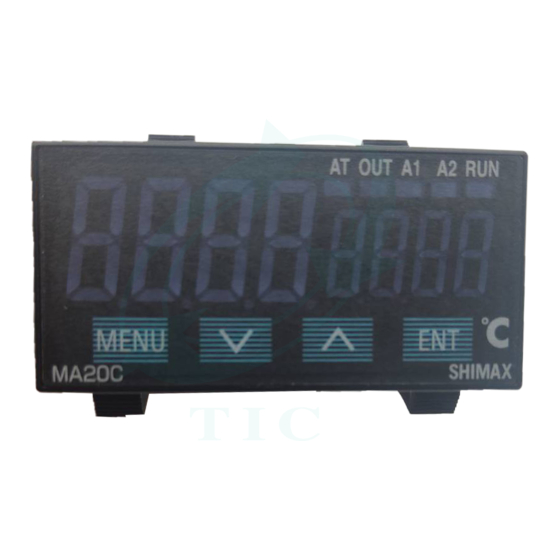
MA20C
Digital controller
Instruction manual
Thank you for purchasing SHIMAX products. Please check that the delivered
Product is the item you ordered. Please do not begin operating this product until
You have read this instruction manual thoroughly and understand its contents.
「Notice」
Please ensure that this manual is given to the final user of the instrument.
Preface
This instruction manual is meant for those who will be involved in wiring,
installation, operation and routine maintenance of the MA20C.
This manual describes the care, installation, wiring, function, and proper procedures
regarding the operation of MA20C. Keep this manual on hand while using this device.
Follow the guidance provided herein.
1.Matters regarding safety
For matters regarding safety, potential damage to equipment and/or facilities and additional
instructions are indicated as follows.
◎This heading indicates hazardous conditions that could cause injury or death of personnel.
Exercise extreme caution as indicated.
「
WARNING」
◎This heading indicates hazardous conditions that could cause damage to equipment and/or
facilities. Exercise extreme caution as indicated.
「
CAUTION」
◎This heading indicates additional instructions and/or notes
「NOTE」
「
WARNING」
MA20C is designed for controlling temperature, humidity, and other physical subjects.
It must not be used in any way that may adversely affect safety, or working conditions.
「
CAUTION」
To avoid damage to the connected equipment, facilities or the product itself due to a fault of
the product, safety countermeasures must be taken before usage, such as proper installation
of the fuse and the overheating protection device. No warranty, expressed or implied, is valid
in the case of usage without having implemented proper safety counter measures.
「
CAUTION」
●The
mark on the plate affixed to the instrument:
On the terminal nameplate affixed to the case of your instrument, the
This is to warm you of the risk of electrical shock which may result if the charger is touched while it is energized.
●The external power circuit connected to the power terminal of this instrument must have a
means of turning off the power, such as a switch or breaker.
Install the switch or breaker adjacent to the instrument in a position which allows it to be
operated with ease, and with an indication that it is a means of turning off the power.
●Fuse:
Since the instrument does not have a built-in fuse, do not forget to install a fuse in the power
circuit to be connected to the power terminal. The fuse should be positioned between the switch
or breaker and the instrument and should be attached to the L side of the power terminal.
Fuse Rating: 250V AC 0.5A/medium lagged or lagged type.
Use a fuse, which meets the requirements of IEC127.
●Load voltage/current to be connected to the output terminal and the alarm terminal
should be within the rated range. Otherwise, the temperature will rise and reduce the life
of the product and/or result in problems with the product.
●Voltage different from that of the input specification should not be connected to the input terminal.
It may reduce the life of the product and/or result in problems with the product.
●Input, voltage pulse output, and current output are not isolated electrically from inside circuits.
When ground thermocouples are used, the control output terminal should not be connected to earth.
(If connected, wraparound causes errors.)
●This instrument is provided with a vent for heat discharge. Take care to prevent metal or other
foreign matter from obstructing the vent. Failure to do so may result in problems with the
product and may even result in fire.
●This instrument has basic insulation between the power supply and the secondary
circuit.If accessible Safety Extra Low Voltage (SELV) circuits are to be connected to
Signalinput/output terminals (Input, Output(SSR, Current, Voltage), DI, CT, Analog
output, Communication, and other secondary circuit), ensure to provide a basic insulation
between the SELV circuits and these terminals (For example, use transformer which has a
basic insulation or higher degree of insulation). The basic insulation requires a clearance at
least 1.5mm and a creepage of at least 3.0mm.
●Do not block the vent or allow dust to accumulate. The rise in temperature or insulation failure caused
by blocking the vent may result in reducing the life of the product and/or problems with the product.
●Repeated tolerance tests against voltage, noise, surge, etc. may lead to deterioration of the instrument.
●No modification or irregular usage is allowed.
2.
Introduction
2-1.Check before use
Before using this product, you are required to check the model code, the external view of the product
and the accessories to make sure that there is no error, damage, or shortage of delivered items.
Confirmation of model code: Check the model codes on the case of the product to ascertain
that the delivered item is what you ordered by referring to the following code table.
Example of model code
MA20 C- M C F- 2N- 0
Item
1.Series MA20 2. Classification C--:controller 3.Iinput M: multi V: voltage I: current
4. Control output
5. Power Supply
6. Option
7. Remarks
Check of accessories
Instruction manual:
「NOTE」:Contact our representative or our local office concerning any problems
2-2.Caution for use
(1) Avoid operating the front panel keys with hard or sharp objects.
Touch the keys lightly with fingertips.
(2) To clean, wipe gently with a dry cloth. Avoid using solvents such as thinner.
3.Installation and wiring
3-1.Installation site (environmental conditions)
mark is printed.
Do not use this instrument under the following conditions.
Otherwise, the likelihood of fire and/or other dangerous situations are considerable.
(1) Where flammable gas, corrosive gas, oil mist or dust that can deteriorate.
electrical insulation is generated or is abundant.
(2) Where the temperature is below -10℃ or above 60℃
(3) Where the humidity is over 90%RH or where condensation occurs.
(4) Where highly intense vibration or impact is generated or can affect the operation of the product.
(5) Near high voltage power lines or where inductive interference can affect the operation of the product.
(6) Where there are dewdrops or direct sun light.
(7) Where the altitude is above 2,000m.
「NOTE」: The environmental conditions here comply with the installation
3-2. Mounting.
(1) Machine the mounting hole by referring to the panel-cut illustration in Section 3-3.
(2) Applicable thickness of the mounting panel is 1.2 ~ 3.2mm. (With metal fittings, it can be 1.0 ~ 4.0mm.)
(3) As this product provides mounting fixture, insert the product into the panel.
「NOTE」:MA20C is a panel set-up type. Please use the product after setting up to the panel.
1
「
CAUTION」
1
2
3
4
5
6
C: contact S: voltage pulse I: current (4 ~ 20mA) V;(0~10V)
F-: 90 – 264V AC
L-: 21.6 – 26.4V DC/AC
0N-: without 1N-: alarm output 1 point 2N-: alarm output 2 points
0D-: external control input (DI) 2 points
1D-: alarm output 1 point + external control input (DI) 2 points
0T-: analog output (4 ~ 20mA)
1T-: alarm output 1 point + analog output
2T-; alarm output 2 point + analog output
0R-:communication of RS-485
1R-: alarm output 1 point + communication of RS-485
1B-: alarm output 1 point with buzzer 2B-:alarm output 2 point with buzzer
0: without
9: with
1 set
with the product and accessories, or for any inquiry.
「
CAUTION」
category Ⅱ and the pollution degree 2 set by IEC664.
7
August. 2020
MA20CF-1DE
Advertisement
Table of Contents

Related Manuals for Shimax MA20C


Summary of Contents for Shimax MA20C
- Page 1 ●This instrument is provided with a vent for heat discharge. Take care to prevent metal or other 「NOTE」:MA20C is a panel set-up type. Please use the product after setting up to the panel. foreign matter from obstructing the vent. Failure to do so may result in problems with the product and may even result in fire.
- Page 2 3-3.External dimension and panel cutout External View of Installation with Metal fittings MA20C external dimensions (unit: mm) Packing AT OUT A1 A2 RUN MENU MA20C SHIMAX 3-4.Wiring 「 WARNING」 Panel(Thickness of applicable panel 1.2~3.2mm 1~4mm with metal fittings) ◎To prevent electrical shock, turn off electricity during wiring operation.
- Page 3 ④ MENU Press key to move on to the next screen in each screen. MA20C SHIMAX Press key for three seconds on the basic screen and the screen jumps to the lead screen of Mode 1. Press MENU key for three seconds on the lead screen of 4-2.Description of parts on the front panel...
- Page 4 5-4.Description of screens Alarm 1 operating point setting screen Initial value: higher limit absolute value within measuring range (1)A group of basic screens higher limit of scaling range Basic screen Lower limit absolute value within measuring range Higher limit deviation 2000 Executed SV initial value: Sensor input Linear input...
- Page 5 (3)A group of Mode 2 screens Integral time (I) setting screen Initial value: 120 sec. Lead screen of Mode 2 Setting range: OFF, 1 ~ 6000 sec. There is basically no need of setting on this screen when AT is executed. This screen is displayed when key is pressed on the lead screen of Mode 1, or when...
- Page 6 Alarm 1 differential gap setting screen Alarm 2 latching setting screen Initial value: 5unit Initial value: 、 Setting range:1~999unit Setting range: ON-OFF differential gap of Alarm 1 can be set on this screen. The same as those of Alarm 1 This screen is not displayed when Alarm 1 mode is ,and When measuring range, unit, scaling range or Alarm 1 mode is changed, the...
- Page 7 (7)A group of Mode 6 screens 5-5. Measuring range code table A group of Mode 6 screens are analog output option setting screens. Input type Code Measuring range (℃) ( ) When the option is not added, these screens are not displayed. Unit code Unit code R...
- Page 8 Communication of RS-485 Power supply The contents of this instruction are subject to change without notice. S H I M A X CO., LTD. URL http://www.shimax.co.jp Head Office: 190 Shimoniiyachi, aza, yotsuya, Daisen-shi, Akita 014-0102, Japan Phone: 0187-86-3400 Facsimile:0187-62-6402 PRINTED IN JAPAN...
Need help?
Do you have a question about the MA20C and is the answer not in the manual?
Questions and answers