
Subscribe to Our Youtube Channel
Related Manuals for Analyticon Urilyzer 100 Pro


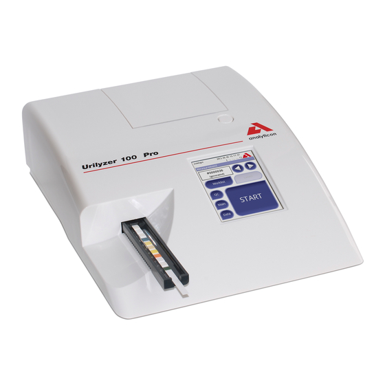
Summary of Contents for Analyticon Urilyzer 100 Pro
- Page 1 Urilyzer 100 (Pro) ® User Manual Analyticon Biotechnologies AG Am Muehlenberg 10 35104 Lichtenfels - Germany info@analyticon-diagnostics.com www.analyticon-diagnostics.com agile - affordable - accurate...
- Page 2 No part of this document may be reproduced or transmitted in any form or by any means, electronic, mechanical or otherwise, for any purpose, without the express written permission of Analyticon. Analyticon may have patents or pend- ing patent applications, trademarks, copyrights or other intellectual or industrial property rights covering this document or subject matter in this document.
-
Page 3: Table Of Contents
Table of Content Table of Contents Introduction How to use this manual Quickstart System description Measuring principle Components and Functions Instrument and Labeling Symbols Unpacking & Set Up Unpacking Setting up Analyzer software updates Use of the instrument Screens Interacting with the touch screen Data input: Barcode reader, keyboard Flow-chart of the menu structure Start-Up Wizard... - Page 4 Table of Content 10. Options menu 10.1 Strip LOT 10.2 View Settings 10.3 User Options 11. Instrument Settings 11.1 Language 11.2 Date, time 11.3 Printout 11.4 Output (Connectivity: Transfer/Export) 11.5 Measurement 11.6 Strip options 11.7 Database management 11.8 QC options (Pro only) 11.9...
-
Page 5: Introduction
Introduction 1 Introduction Due to software changes, some screens on the instrument may appear slightly different from those in this manual. What does the analyzer do? The Urilyzer 100 analyzer is a lightweight instrument for reading CombiSceen Plus urinalysis strips (CombiScreen 11SYS Plus, CombiScreen 7SYS Plus and CombiScreen 5SYS Plus). - Page 6 Introduction Symbol/Sign Explanation CAUTION: Indicates a potentially hazardous situation that if not avoided could result in personal injury or damage to the instru- ment. This symbol is also used to highlight situations that can compromise results. Cautions appear in bold type. BIOHAZARD: Indicates a potentially dangerous situation involv- ing the presence of biohazardous material.
- Page 7 Introduction Abbreviations The following abbreviations are used: Abbreviation Definition Alternating Current arbitrary ASTM American Society for Testing Material conv conventional comma separated values Direct Current European Standard Identification number Light Emitting Diode negative norm normal positive Standard International...
-
Page 8: Quickstart
Quickstart 2. Quickstart Unpack the instrument and place it on an even, hard surface (for detailed instal- lation instructions see 4. Unpacking & Set Up). Load the strip tray and the printer paper. Connect the power supply and turn the reader on with the On/Off-switch (See ... - Page 9 Quickstart After approx. 60 seconds the pad results will be dis- played on the screen. If Autostart is ON: The result screen will be dis- played until you remove the test strip from the tray. Once the strip is removed, the display automatically returns to the Measurement screen.
-
Page 10: System Description
System description 3. System description 3.1 Measuring principle The test strip is moved below a fixed measurement unit on a slide called test strip tray with an embedded reference pad. The analyzer reads the reference pad, fol- lowed by each of the test pads on the strip. The optical unit contains four LEDs that emit light at various wavelengths. -
Page 11: Components And Functions
System description 3.2 Components and Functions 9 10 Front view Rear view Component Function 1. Printer cover Flips up for insertion of printer paper 2. Printer cover button Push to open the printer cover 3. Display LCD touch screen for interfacing with the user 4. -
Page 12: Instrument And Labeling Symbols
System description 3.3 Instrument and Labeling Symbols This section describes the symbols that appear on the exterior of the Urilyzer 100 analyzer, the power supply provided with the instrument, the packaging in which the instrument was delivered and the supplies of reagent strips which you will use with the instrument. - Page 13 System description Indicates a power on/off USB port symbol button Ethernet port symbol DC Adaptor Polarity Centre Positive Do not use if package is Keep this way up damaged Handle with care Stack no more than 4 Temperature limitation Humidity limitation 60°C (140°F) -25°C...
-
Page 14: Unpacking & Set Up
Unpacking & Set Up 4. Unpacking & Set Up 4.1 Unpacking Read the Urilyzer 100 Operator’s Manual carefully before installation, so as to ensure proper operation of the analyzer from the outset. Follow the specified installation instructions carefully. Otherwise, inac- curate results or damage to the analyzer may occur. - Page 15 Unpacking & Set Up • D o not expose the instrument to strong light sources (e.g. direct sun- light) 4.2.1 Plugging analyzer in Only use the power supply adapter included with the unit. Connect the analyzer to grounded power outlets only. 1.
- Page 16 Unpacking & Set Up 4.2.3 Loading the paper roll Open the printer cover by pushing the printer cover button. The cover can then be lifted back. The printer head may be hot, do not touch it. Place the paper roll in the compartment and pull out the first few centimeters of paper just beyond the edge of the compartment.
- Page 17 Unpacking & Set Up 4.2.4 Interfacing to a computer The instrument can send results to a computer via the serial port located on the back of the analyzer. This requires a D-sub, 9-pin serial cable (male on instru- ment side, female on PC side). Connections: Urilyzer 100 Host (PC pinout 9-pin)
-
Page 18: Analyzer Software Updates
LCD failure. In this case the test strip tray will not be retracted. 4.3 Analyzer software updates From time to time Analyticon will add new features and make improvements to the Urilyzer 100 analyzer software. Updating the software is a simple procedure, but for the upgrade to work prop- erly, it is important to follow the instructions below precisely. - Page 19 Unpacking & Set Up Plug the USB flash drive into one of the USB A connectors on the back of the device. Wait until the disk icon appears in the status line. The icon shows that the USB flash drive was recognized by the system. ...
-
Page 20: Use Of The Instrument
Use of the intrument 5. Use of the instrument All inputs are done via the touch screen (if no external keyboard or barcode reader is attached). 5.1 Screens The touch screen guides you through the operation of the Urilyzer 100 analyzer. The screen displays messages, instructions and options to which you respond by touching the appropriate area on the screen. - Page 21 Use of the intrument Where to touch the screens Generally the framed areas respond to touching the screen: buttons, checkbox buttons, round radio buttons and text input fields. Buttons The round buttons with an edge are used to trigger action and to navigate in the menu.
- Page 22 Use of the intrument Round radio buttons These buttons typically appear on screens that require a selection from several items. The button with a filled circle is the current selection. To change your selection, touch an unfilled circle. The newly selected circle (but- ton) will now be highlighted.
-
Page 23: Data Input: Barcode Reader, Keyboard
Use of the intrument 5.2.1 Touch screen calibration When touch screen calibration is required? The instrument’s touch screen is properly calibrated in the factory. However it may be necessary to recalibrate the touch screen. If you go to touch a particular button of the screen and nothing happens, or another menu pops up, your touch screen is not calibrated correctly. - Page 24 Use of the intrument Entering data for input fields (Sample ID, Patient ID, Operator ID, etc.) When an input field is active enter the data directly with the keyboard, no short- cut button is required. To delete a character, use backspace. To cancel the input and move back to the previous screen, press Escape.
-
Page 25: Flow-Chart Of The Menu Structure
Use of the intrument 5.4 Flow-chart of the menu structure Main Measure Start Sample ID Patient ID Clarity Color Comment Worklist Modify Delete Change order Transfer from Print Latest result Data View Modify Print Transfer Select Delete Print Transfer Filter QC Meas Start Solution... - Page 26 Use of the intrument Main Options Strip, LOT LOT code View settings Print Settings User options Autostart on/off Auto transfer on /off Autoprint on /off Sound on /off LCD brightness Normal/Fast mode Settings Language Date/Time Power Manag . Log Export Printout Output Color list...
-
Page 27: Start-Up Wizard
Start-Up Wizard 6. Start-Up Wizard The first time your Urilyzer 100 analyzer is turned on, it will take you through a quick set up procedure. This procedure will allow you to select the basic func- tions of the analyzer so you can use the analyzer with your choice of settings. The Start-Up Wizard will allow you to select the following settings: • Language ... -
Page 28: Testing
Testing 7. Testing The analyzer can be set up to be as simple or sophisticated as you prefer. You may simply insert a dipped urinalysis strip into the analyzer and the result will be reported. By modifying the user options the measurements can be started, printed and transferred automatically. - Page 29 Testing Place the reagent strip in the chan- The instrument will automatically de- nel of the table with the test pads fac- tect an applied strip. The measurement ing up. Slide the strip to end of the cycle will be started. channel.
- Page 30 Testing To abort a measurement press the Back icon on the Analyzing screen and press Stop/Drop on the Measurement screen. Comment can be also added during the countdown time. After approximately 60 seconds the pad results will be displayed on the screen and the test strip tray is automatically moved out of the analyzer.
-
Page 31: Test Features And Customization
Testing How to modify the result? Edit button on the second result Results can be modified by pressing the page, before the record is printed or sent. All fields can be modified except date and pad results, even if the particular field was not available during the acquisition. - Page 32 Testing The option to enable Fast mode only appears on the User options screen, if this option is enabled on the Settings»Measurement screen. 7.2.2 Customization of testing On the Settings»Measurement screen you can cus- tomize which fields are enabled during acquisition, to disable fast mode at the system level or to allow analysis of (partially) dry strips and modify the set- tings.
- Page 33 Testing 7.2.3 Strip checking events Errors in sample handling and testing procedure may lead to false results. In order to further improve the diagnostic decision making process advanced strip recognition features were introduced in Urilyzer 100. The outcome of these features is categorized into three groups: R1.
-
Page 34: Full Test
Testing 7.3 Full Test The description of the required preparations and the testing process can be found at 7.1 Quick Test. This section only provides additional information on the data input process presuming that all additional fields (sample ID, patient ID, color and clarity) are enabled. - Page 35 Testing Patient ID: Use the onscreen key- Patient ID: Touch Apply&Next, when board, the attached keyboard or the you have finished entering the patient barcode reader to enter the patient ID. ID and proceed to the next screen. To The Patient ID field can be left empty.
-
Page 36: Latest Result
Testing After all data have been entered the next screen displayed will either be: Analyzing … — if the strip is still being analyzed Result — if analyzing the strip has been completed It is not required to input all data during the incu- bation time, the system will analyze the strip in the background and move out the test strip tray. - Page 37 Testing In the Worklist menu you can: 1) Manually add, modify, delete the worklist items 2) Download the worklist from the LIS 3) Modify the sequence of the items 4) Search for a sample ID in the worklist 5) Print the worklist 6) Delete the whole worklist Legend ...
- Page 38 Testing 7.5.1 Worklist window in the Measurement menu Back button, the first When you return the Measurement screen with the worklist item will be active in the list window. If you need to manually change the order in the Measurement screen, use the left and right buttons to cycle through the worklist.
-
Page 39: Recall Results
Recall Results 8. Recall Results The Urilyzer 100 has memory for 1000 (PRO 3000) measurements. Every result is automatically saved after the analysis in an indexed database. The database enables you to search, view, print and transfer patient test results. ... -
Page 40: Result View
Recall Results To view details of a patient result, touch the View button. The first page of the patient’s result will be displayed on the screen. 8.2 Result view The pad results are listed on the first page. You can use the up and down navigation buttons ... -
Page 41: Modifying The Active Selection Of Results
Recall Results Active filters are labeled with orange background. On the first page of the Filter screen, the active fil- ters from the second page are listed above the navi- gation buttons. To switch off filtering press the Filter OFF button. To return to the list of results, press Return. -
Page 42: Action With Selected Items
Recall Results Select all Select all button on the Database»Selected To select all records press the screen. Invert selection Invert selection button on the To invert the actual selection, press the Database»Selected screen. Remove selection Remove selection button on the To remove all selections, press the Database»Selected screen. -
Page 43: Quality Control Testing
Several commercial controls are available. Controls may vary in number of levels or components, necessity for reconstitution or ready to use, type and volume of container. Analyticon supports the use of CombiScreen Control PN or Quantimetrix Corporation Dipstick Controls as these controls provide the necessary color development with CombiScreen Plus strip. -
Page 44: Qc Options
Quality Control Testing 2. The QC measurement screen can be reached by the QC button from the Measurement screen or by the QC Meas button from the Main screen. QC Testing 3. All QC measurements are stored in a separate database, to reach them press ... - Page 45 Quality Control Testing The QC check can be set for 1) two level urine control solutions (L2: negative/normal and positive/abnormal), 2) three level urine control solutions (L3: negative/normal, low and high positive/ abnormal). If strong user security is applied ( 11.14.2 Modifying security settings) the nor- mal users are not able to modify the QC settings, so the QC policy determined...
-
Page 46: Qc Testing
Screen Plus test strips. We recommend using CombiScreen Control PN which is available from Analyticon Biotechnologies AG. Alternatively the controls from Quantimetrix Inc. can be used to carry out the QC-Check. Controls of other manufactur- ers may provide abnormal results due to non-specific colorations of the test pads. -
Page 47: Recall Qc Results
Quality Control Testing The remaining lockout time together with the date is displayed in the information windows of the Main screen. The maximum displayed negative value is –90. It may mean that more than 90 days has passed since the limit or a successful QC was never performed. 9.3 Recall QC Results All QC measurements are stored in the QC memory, which is separated from the memory for the patients’... -
Page 48: Options Menu
Options menu 10. Options menu The Options screen displays the following informa- tion: • strip type and LOT code information, • output settings. The following functions can also be reached from this screen: • Strip LOT, • View Settings, • U ser Options (auto features; fast mode; sound; LCD brightness), • Instrument Settings. - Page 49 Options menu NOTE: These features can be modified by any operator and stored separately for each operator (Pro) Fast mode (serial reading): if enabled, the test strip is measured directly after Measure is pressed on the Measurement screen (note: in fast mode the large start button is renamed to Measure and the background is changed to orange).
-
Page 50: Instrument Settings
Instrument Settings 11. Instrument Settings Your Urilyzer 100 analyzer allows you to change settings to suit your workplace requirements. Instrument settings can be reached from Main»Options»Settings. The list of available settings may vary according to authenticated user level. Settings 1/2 Settings 2/2 To navigate between settings pages use the back and forward arrows. -
Page 51: Language
Instrument Settings 11.1 Language To change the operating language select the desired language from the list and apply change. If the translation is partially done in the selected language, the non-transleted texts appear on English. 11.2 Date, time The date and time are displayed on the header and are recorded with the test results. -
Page 52: Output (Connectivity: Transfer/Export)
Instrument Settings 11.4 Output (Connectivity: Transfer/Export) At the Output settings you can define how the Urilyzer 100 will connect to other systems or storage devices. The analyzer supports many possibilities for trans- ferring the results through an interface (serial, USB or file): 1. - Page 53 Instrument Settings 11.4.1 Bidirectional protocol (LIS2-A2) The two-way digital transmission protocol of Urilyzer 100 analyzer regarding remote requests and results between Urilyzer 100 and information systems is based on the NCCLS LIS2 A2*) approved standard. It enables Urilyzer 100 and any standard LIS system, to establish a logical link for communicating text to send results and requests in a standardized and interpretable form.
-
Page 54: Measurement
Instrument Settings 11.4.3 UTF8 unidir text (STUB) 11.5 Measurement The detailed description of the Measurement screen can be found in 7.2.2 Customization of testing. 11.6 Strip options The main strip options screen shows the available strip types. To modify the strip settings select the ap- propriate strip type and press the order, sensitivity button. -
Page 55: Database Management
Instrument Settings To modify the displayed pad order: 1 Select the pad. 2 Press the Move button. It will be active and its background will be changed to orange. 3 Use the up and down arrows to move the position of the selected pad. -
Page 56: Power Management
4) Remove the USB flash drive. 11.11 Editing color and clarity list (Pro only) The Urilyzer 100 Pro units allow the possibility to customize the urine color and clarity list values according to standard lists determined by your facility’s policy. -
Page 57: Ethernet Interface Configuration (Pro Only)
Apply button. To restore the original list, press the Restore Default button. 11.12 Ethernet interface configuration (Pro only) To connect the Urilyzer 100 Pro analyzer to the net- work via Ethernet interface through TCP/IP, you have to configure the Ethernet interface. -
Page 58: Operators (Pro Only)
Instrument Settings 11.14 Operators (Pro only) The operators screen is used to manage the system security settings and to manage the active operators. Legend List of operators Delete active operator System security settings (accessible for Supervisor group members) ... - Page 59 Instrument Settings 11.14.1 Concept: Operator levels Each consecutive level inherits the rights of the previous level. User groups Rights User This is the standard user group. Members of this group can perform routine actions such as • worklist management, • perform test, • run control, • report results (printing, exporting), • modify user options.
- Page 60 Instrument Settings 4. Self-add with password Login with operator password for measurement; system settings are protected. Users can add themselves as ‘user’ level operators at login, however it is manda- tory for them to select a password. Audit trail applies. 5. Secure Full security applied: only registered users may login. Users can be registered by administrators (‘admin’). Audit trail applies.
- Page 61 Instrument Settings If active, the following switches are automatically disabled: ‘auto login’, ‘self add operators at login’, ‘login without password ‘. These switches can be mixed to create the desired security level. If enabled, the ‘login without password’ and ‘operators on login’ screen can be separately modified for each operator. In custom security mode further information is displayed in parenthesis after the user group of the selected operator.
- Page 62 Instrument Settings 11.14.4 Understanding security levels (Advanced topic) Anony- Self-add Open mous Self-add with Secure system usage password Auto login On On Off Off Off Auto login Admin User rights Self add Off On ...
- Page 63 Instrument Settings 11.14.5 User management To add a new user, push the Add new operator but- ton at the right-bottom corner on the Operators screen. 1. On the next screen set the Operator ID. 2. On the second screen a. determine the rights of the operator: user, ad- min, supervisor.
-
Page 64: Cleaning & Maintenance
Cleaning & Maintenance 12. Cleaning & Maintenance As a general preventive action, always keep the outside of the Urilyzer 100 analyzer clean and free of dust. 12.1 Cleaning the analyzer When the analyzer is turned off, wipe the outside (including the display) with a damp (not wet) cloth and a mild detergent. - Page 65 Cleaning & Maintenance Do not push the tray fully into the analyzer as the tray may become jammed and prevent the use of the analyzer. When the analyzer is turned on the self-check begins automatically and veri- fies that the reference pad is in good condition. If not, an error message will be displayed.
-
Page 66: Troubleshooting
Troubleshooting 13. Troubleshooting Your Urilyzer 100 analyzer will operate properly if you follow the directions for using and cleaning the instrument. Advisory messages will be displayed when your attention is required on any disorder or result of a performed action. The user interface messages can be categorized into the following groups: 1. -
Page 67: List Of Errors And Information Messages
Troubleshooting 13.1 List of Errors and Information Messages In case of an error, try to solve it according to the below trouble-shoot guide first. If the failure remains, please contact your service representative. Irregular or slow movement of test strip tray If movement of the test table is irregular or slow, this may be caused by the heavy buildup of dried urine on the test table. - Page 68 Troubleshooting Legend Categories (C.): Type (T.): 1. E Error messages 1. S Status line 2. W Warning messages 2. TP Timed pop-up window 3. I Information messages 3. P Pop-up window 4. R Result view Text Long text Action Head Head hardware error.
- Page 69 USB pen- (re)insert USB pendrive. drive is connected properly and recognized by the system. If required, re-initialize the USB port by pressing the Analyticon logo on the top right corner. Output Output aborted. Restart transfer. aborted Please start again.
- Page 70 Troubleshooting Text Long text Action Output Output port cannot connect The system continuously tries connect to server. Please check to deliver the output. In case ethernet cable, ethernet of success, the error will auto- configuration in settings matically disappear. and server IP address and If the error persists, please port number.
- Page 71 Troubleshooting Text Long text Action E196 E DB failure: configuration is Contact your service repre- corrupted. Please check sentative. the configuration settings. Either see Page 61 for ‘full database clear’. E195 E Worklist DB failure: cannot Contact your service repre- write new item. sentative. Either see Page 61 for ‘full database clear’.
- Page 72 Please insert it. ognized by the system. If required, re-initialize the USB port by pressing the Analyticon logo on the top right corner. W134 W Worklist DB failure: pos- Database failure. sible data loss! Trying to The system is trying to repair repair.
- Page 73 Troubleshooting Text Long text Action W132 W Config DB is recreated. System settings are regener- Previous configuration is ated. Set the configuration lost! options again. If problem occurs multiple times, Contact your service representative. W131 W DB failure: possible data Data loss probably occurred.
- Page 74 Troubleshooting Text Long text Action I101 Sample ID was not found, please try again or cancel the search. 13.1.1 Testing / Measurement Result Errors These error codes are stored together with the results in the database perma- nently and are also displayed after the testing procedure. Long text Testing: Error Source &...
- Page 75 Troubleshooting Long text Testing: Error Source & Action E271 E Strip error while calculat- A.) Not the proper test strip type was ing the results of meas- used. urement Ensure that the strip type selected in set- tings is being used (Chapter 11.6). Repeat the test with a new test strip.
- Page 76 Troubleshooting Long text Testing: Error Source & Action E265 E Measured value out of Non-realistic data was collected. valid range for one or A.) Ensure that the strip type selected in more pads. settings is being used (Chapter 11.6). B.) Check strip quality Check the expiry date of the strip.
- Page 77 Troubleshooting SW Update Long text Action E597 E Internal configuration Restart update. If problem remains, Con- failure! (Please call Serv- tact your service representative. ice) E572 E Failed install: …… Corrupted or missing files. Check and verify the software update sources on the media.
-
Page 78: Problem Checklist
Troubleshooting 13.2 Problem Checklist Serial Number: ______________________ Installation Date: ______________________ YES NO Have you reviewed the error messages on pages 68 to 77? Please record any error messages that have been displayed: ———————————————————————————— ———————————————————————————— ———————————————————————————— Does the test strip tray move out to the “home” position when the ... -
Page 79: Appendices
Appendices 14 Appendices 14.1 Appendix A: Results table The Urilyzer 100 prints the results in the following gradation of concentration: Parameter Conventional SI Units (SI) Arbitrary Units Units (Conv.) (Arb.) (Bilirubin) 1 mg/dl 15 µmol/l 2 mg/dl 35 µmol/l 4 mg/dl 70 µmol/l norm norm... - Page 80 Appendices Parameter Conventional SI Units (SI) Arbitrary Units Units (Conv.) (Arb.) (Nitrite) (Leukocytes) 25 Leu/µl 25 Leu/µl 75 Leu/µl 75 Leu/µl 500 Leu/µl 500 Leu/µl 1.000 1.000 1.000 (Specific Gravity) 1.005 1.005 1.005 1.010 1.010 1.010 1.015 1.015 1.015 1.020 1.020 1.020 1.025...
-
Page 81: Appendix B: Specifications
Appendices 14.2 Appendix B: Specifications Type: reflectance photometer with 4 discrete wavelengths 505, 530, 620, 660 nm Throughput: maximum 50 strips/hour (in normal mode) Display: 3.5” QVGA touch-screen LCD (resolution: 240x320) Memory: 1000 test results / 500 QC results Pro: 3000 test results / 1000 QC results Printer: internal thermo printer (roll diameter max. -
Page 82: Appendix C: Analyzer Default Settings
Appendices 14.3 Appendix C: Analyzer Default settings User options: Output: Autostart: ........ON unidir text (UTF8) Auto print: ......... ON Header: ........empty Auto transfer: ......OFF Frame+CHKSUM: ..... ON Sound: ........ON Output units: ....conv-arbitr LCD brightness (%): ....100 Baud rate: ........9600 Measurement: QC options: color: ........OFF... -
Page 83: Appendix D: Safety Information
Appendices 14.4 Appendix D: Safety information The Urilyzer 100 was designed and manufactured to comply with the following international regulations, and left the factory in a safe condition. To keep the analyzer in a safe condition, you must observe all instructions and warnings included in this manual. - Page 84 Appendices 14.4.1 Protecting yourself from biohazards This information summarizes the established guidelines for handling laboratory biohazards. Use this summary for general information only. It is not intended to replace or supplement your laboratory or hospital biohazard control proce- dures. Urine specimens should be handled at Biosafety Level 2 as recommended for any potentially infectious material in the Centers for Disease Control and Preven- tion manual, Biosafety in Microbiological and Biomedical Laboratories, 2009*).
-
Page 85: Urilyzer 100 Intended Use And Indications For Use
The Urilyzer 100 urine analyzer is an easy to use, bench top instrument which is intended for in vitro diagnostic use with CombiScreen 11SYS Plus, 7SYS Plus and 5SYS Plus reagent strips manufactured by Analyticon. This system performs semi-quantitative detection of the following analytes in urine: Bilirubin, Urobilino- gen, Ketones, Ascorbic Acid, Glucose, Protein (Albumin), Blood (Hemoglobin), pH, Nitrite, Leucocytes and Specific Gravity.
Need help?
Do you have a question about the Urilyzer 100 Pro and is the answer not in the manual?
Questions and answers