
Related Manuals for MAXA OTA Series

Summary of Contents for MAXA OTA Series
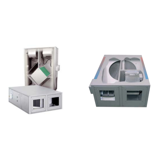
- Page 1 SERIE SERIES OTA-AD SERIE SERIES UNITÀ DI RECUPERO CALORE HEAT RECOVERY UNIT...
- Page 2 Questo libretto d'istruzione è parte integrante dell'apparecchio e di conse- This instruction book is an integral part of the appliance and as guenza deve essere conservato con cura e dovrà SEMPRE accompagna- a consequence must be kept carefully and must ALWAYS re l'apparecchio anche in caso di sua cessione ad altro proprietario o uten- accompany the appliance even if transferred to other owners or te oppure di un trasferimento su un altro impianto.
-
Page 3: Symbols Used
SIMBOLOGIA SYMBOLS USED AVVERTENZA WARNING PERICOLO DANGER PERICOLO RISCHIO DI SCOSSE ELETTRICHE DANGER RISK OF ELECTRIC SHOCK ATTENZIONE SOLO PERSONALE AUTORIZZATO ATTENTION ONLY AUTHORISED STAFF DIVIETO PROHIBITION IDENTIFICAZIONE UNITA’ IDENTIFICATION OF THE UNIT Modello / Model Numero di matricola / Serial number Via Gettuglio Mansoldo - 37040 Arcole (VR) Tensione [V] / Voltage [V] Numero di fasi / Number of phases... - Page 4 4.1 Installazione accessori VVM, C3V, PCM pag. 28 4.1 Installation of accessories VVM - C3V - PCM page 28 serie OTA 4.2 Schemi elettrici pag. 30 OTA series wiring diagrams page 30 serie OTA-AD 4.3 Schemi elettrici pag. 35 OTA-AD series wiring diagrams page 35 4.4 Schema elettrico sistema BIOXIGEN ®...
- Page 5 The OTA series had been designed to resolve these probles by the use of Le serie OTA, intendono risolvere questi problemi utilizzando un recupe- static exchangers.
-
Page 6: Caratteristiche Tecniche
1.1 CARATTERISTICHE GENERALI 1.1 GENERAL CHARACTERISTICS SERIE OTA OTA SERIES • Recuperatore di calore ad alto rendimento di tipo statico a piastre in alluminio (serie OTA) con flussi aria mantenuti separati da apposita • High efficiency heat recovery, cross flow and static type plate exchan- sigillatura. - Page 7 1.2 DATI TECNICI UNITÀ OTA 1.2 OTA UNIT TECHNICAL DATA MODELLO / MODEL Portata aria nominale / Nominal air flow 1580 1850 2250 2950 3920 Pressione statica utile / External static pressure Assorbimento max. totale macchina / Total max absorbed current Livello di pressione sonora / Sound pressure level db (A) VENTILATORI / FANS...
- Page 8 1.3 ORIENTAMENTI POSSIBILI OTA 1.3 OTA POSSIBLE CONFIGURATIONS In funzione della configurazione della rete e dello spazio disponibile è According to the configuration of the installation and the space available, possibile scegliere, sia per i modelli orizzontali che per quelli verticali, fra both for horizontal and vertical models one of four possible layouts can be quattro possibili orientamenti, come di seguito illustrato.
- Page 9 Bypass for free cooling. By pass free cooling. The structure of horizontal models OTA 100-175-200-250-300-400 with Per i modelli orizzontali OTA 100-175-200-250-300-400 con orientamen- configuration type 03 or 04, features a cutout section for creating a to tipo 03 o tipo 04, la carpenteria presenta un pretaglio allo scopo di con- bypass for free cooling.
- Page 10 1.3.2 ORIENTAMENTI MODELLI VERTICALI / VERTICAL MODELS CONFIGURATIONS ORIENTAMENTI TIPO 01 / CONFIGURATIONS TYPE 01 ORIENTAMENTI TIPO 02 / CONFIGURATION STYPE 02 01 D 01 S 02 D 02 S Aria espulsa / Exhaust air Aria espulsa / Exhaust air Aria di rinnovo / Fresh air Aria di rinnovo / Fresh air ORIENTAMENTI TIPO 03 / CONFIGURATIONS TYPE 03...
-
Page 11: Dimensioni E Pesi
1.4 DIMENSIONI E PESI 1.4 DIMENSIONS AND WEIGHTS 1.4.1 Dimensioni modelli orizzontali OTA/O 1.4.1 Dimensions of the horizontal models OTA/O Dimensione / Dimension Peso / Weight Modello [kg] Model [mm] [mm] [mm] [mm] [mm] [mm] [mm] [mm] [mm] [mm] Ø gas [mm] OTA 55 OTA 100... - Page 12 1.4.2 Dimensioni modelli verticali OTA/V 1.4.2 Dimensions of the vertical models OTA/V Dimensione / Dimension Peso / Weight Modello [kg] Model [mm] [mm] [mm] [mm] [mm] [mm] [mm] [mm] [mm] [mm] [mm] [mm] Ø gas OTA/V 55 OTA/V 100 1140 OTA/V 175 1300 OTA/V 200...
- Page 13 1.5 DATI TECNICI UNITÀ OTA-AD 1.5 OTA-AD UNIT TECHNICAL DATA MODELLO / MODEL OTA-AD Portata aria nominale / Nominal air flow 1050 1800 2220 2600 3250 4290 Pressione statica utile/ External static pressure Assorbimento max. totale macchina / Total max absorbed current livello di pressione sonora / Sound pressure level db (A) VENTILATORI / FANS...
- Page 14 1.6 ORIENTAMENTI POSSIBILI OTA-AD 1.6 OTA-AD POSSIBLE CONFIGURATIONS ORIENTAMENTO TIPO 01 / CONFIGURATION TYPE 01 ORIENTAMENTO TIPO 02 / CONFIGURATION TYPE 02 (Tipo standard / Standard type) LATO ESTRAZIONE ROTORE EXCHANGER EXTRACTION SIDE LATO ESTRAZIONE ROTORE EXCHANGER EXTRACTION SIDE Aria espulsa / Exhaust air Aria espulsa / Exhaust air Aria di rinnovo / Fresh air Aria di rinnovo / Fresh air...
- Page 15 • Post-heating internal water coil (mod. 100÷400) - BCR • Resistenza elettrica di post-riscaldamento - BER • Batteria interna di post-riscaldamento ad acqua (mod. 100÷400) - BCR (only for OTA series) • Water coil section - SBFR (solo per serie OTA) •...
- Page 16 1.8.4 SEZIONE CON BATTERIA AD ACQUA CALDO/FREDDO - SBFR 1.8.4 COLD/HOT WATER COIL SECTION - SBFR Il modulo SBFR contiene una batteria ad acqua per post-riscaldamento The SBFR module contains a water coil (for both post-heating and o raffrescamento e va posizionato esternamente alla macchina davanti cooling) and has to be located outside the unit in front of the supply air alla bocca di immissione.
- Page 17 Kit V2M / V2M kit Kit V3M / V3M kit Modello / Model Pressione nominale / Nominal pressure PN16 (ISO7268/EN1333) 1 x Filettato gas maschio 3/4” / 1 x Threaded male GAS 3/4” Attacchi connections 2 x Filettato gas maschio 3/4” / 2 x Threaded male GAS 3/4” 1 x Filettato gas femmina 3/4”...
- Page 18 1.8.9 SERVOMOTORI PER SERRANDE - SM / SMR 1.8.9 DAMPER ACTUATORS - SM / SMR I servomotori per serrande SM e SMR consentono la motorizzazione The SM and SMR actuators are suitable to be installed with the SR front della serranda frontale SR o delle serrande dei plenum SP1 e SP2 dampers or with the dampers of SP1 and SP2 plenums.
- Page 19 1.8.12 Duct silencers - SSC 1.8.12 Silenziatori da canale - SSC The OTA air handling units are properly designed and manufactured to almost Le unità di trattamento aria OTA sono progettate e costruite a regola d’arte completely eliminate phenomena of air leaks through the structures and con- con criteri che annullano quasi completamente i fenomeni di trafilamento del- sequently the annoying squealing sound.
- Page 20 1.8.15 PANNELLO DI CONTROLLO UNITÀ - PC 1.8.15 UNIT CONTROL PANEL - PC Il pannello PM, per installazione a parete, consente il controllo della tem- The PM panel is suitable for wall mounting, and is used to control the peratura ambiente inverno/estate, dà il consenso per l’attivazione o l’e- room temperature both in heating and cooling operation, to enable or dis- sclusione della batteria ad acqua o della resistenza elettrica e seleziona able the water coil or the electric heater, and to select the fan operating...
- Page 21 1.8.19 Sistema di sanificazione BIOXIGEN 1.8.19 BIOXIGEN ® purification system Il sistema di ionizzazione dell’aria BIOXIGEN ® è fornito come accessorio opzio- The BIOXIGEN® purification system is provided as a optional acces- nale per le serie OTA e OTA-AD. Viene fornito già assemblato in accoppia- sory for the OTA e OTA-AD series.It is supplied as an already assembled mento ai diversi modelli secondo lo schema seguente element and it is coupled with the different sizes as it is shown in the fol-...
-
Page 22: Installazione E Messa In Servizio
2 - TRANSPORT 2 - TRASPORTO 2.1 Imballaggio 2.1 Packaging • I recuperatori e i loro accessori sono inseriti in scatole di cartone che • The heat recovery unit and their accessories are inserted into cardboard boxes dovranno rimanere integre fino al momento del montaggio. (or polyethylene bubble pack), which must remain integral until assembly. - Page 23 • Prevedere uno spazio libero minimo come indicato nelle figure seguen- possible. ti, al fine di rendere possibile l'installazione e la manutenzione ordinaria e straordinaria. Serie OTA - Modelli orizzontali OTA series - Horizontal models Modello / Model A (mm) OTA/O min. 500 min.
- Page 24 3.5 Posizionamento della macchina 3.5 Positioning of the machine Qui di seguito sono illustrate alcune sequenze del montaggio: Some assembly sequences are illustrated below: 1. Eseguire la foratura a soffitto e fissare quattro tiranti filettati M8 come 1. Drill the ceiling and fix four M8 threaded tie-rods, as indicated indicato in figura.
- Page 25 • The siphon must finally have a cap for cleaning the lower part or must • Il sifone deve infine essere dotato di tappo per la pulizia nella parte however allow quick disassembly for periodical cleaning. bassa o deve comunque permettere un veloce smontaggio per la pulizia periodica.
- Page 26 3.8 Sezione con batteria ad acqua SBFR 3.8 Water coil section SBFR Attenzione: l’installazione della sezione con batteria ad acqua compor- Attention: the installation of the section with water coil leads to additio- ta perdite di carico aggiuntive nel circuito di immissione. Tali pedite nal pressure drops in the introduction circuit.
- Page 27 3.8.1 Collegamento idraulici sezione SBFR 3.8.1 SBFR section hydraulic connections • Le operazioni di installazione e collegamento delle tubazioni sono ope- • The installation and connection operations of the pipes are operations razioni che possono compromettere il buon funzionamento dell'impian- that can compromise the good functioningof the plant or worse, cause to o, peggio, causare danni irreversibili alla macchina.
-
Page 28: Collegamenti Elettrici
4 - COLLEGAMENTI ELETTRICI 4 - ELECTRIC CONNECTIONS Prima di iniziare qualsiasi operazione assicurarsi che la Before starting any operation, make sure that the main power linea di alimentazione generale sia sezionata supply line has been isolated • I collegamenti elettrici ai quadri di comando devono essere effettuati da •... - Page 29 4.1.4 Pannello di controllo unità PC 4.1.4 Unit control panel PC 1. Sfilare la manopola. 1. Take out the knob. 2. Rimuovere la calotta. 2. Remove the cap. 3. Sganciare la piastra attaccata alla base 3. Unhook the plate fixed to the bottom del termostato e al contempo spingerla of the thermostat and at the same time push that verso il basso fino a liberarla.
- Page 30 4.2 Schemi elettrici Serie OTA 4.2 OTA series wiring diagrams SCHEMA ELETTRICO OTA 55 DIRETTO WIRING DIAGRAM OTA 55 DIRECT SCHEMA ELETTRICO OTA 55 con REGOLATORE ELETTRONICO VVM WIRING DIAGRAM OTA 55 with VVM SPEED CONTROLLER SCHEMA ELETTRICO OTA 55...
- Page 31 SCHEMA ELETTRICO OTA 100 – 175 – 200 DIRETTO WIRING DIAGRAM OTA 100 – 175 – 200 DIRECT SCHEMA ELETTRICO OTA 100 – 175 – 200 con SELETTORE DI VELOCITÀ C3V WIRING DIAGRAM OTA 100 – 175 – 200 with C3V SPEED CONTROLLER SCHEMA ELETTRICO OTA 100 –...
- Page 32 SCHEMA ELETTRICO OTA 100 – 175 – 200 con RESISTENZA ELETTRICA BER e PANNELLO DI CONTROLLO PCM WIRING DIAGRAM OTA 100 – 175 – 200 with BER HEATING SECTION and PCM CONTROL PANEL SCHEMA ELETTRICO OTA 250 – 300 DIRETTO WIRING DIAGRAM OTA 250 –...
- Page 33 SCHEMA ELETTRICO OTA 250 - 300 con PANNELLO DI CONTROLLO PCM WIRING DIAGRAM OTA 250 - 300 with PCM CONTROL PANEL SCHEMA ELETTRICO OTA 250 - 300 con RESISTENZA ELETTRICA BER e PANNELLO DI CONTROLLO PCM WIRING DIAGRAM OTA 250 - 300 with BER HEATING SECTION and PCM CONTROL PANEL SCHEMA ELETTRICO...
- Page 34 SCHEMA ELETTRICO OTA 400 (TRIFASE) con PANNELLO DI CONTROLLO PCM WIRING DIAGRAM OTA 400 (THREE-PHASE) with PCM CONTROL PANEL SCHEMA ELETTRICO OTA 400 (TRIFASE) con RESISTENZA ELETTRICA BER e PANNELLO DI CONTROLLO PCM WIRING DIAGRAM OTA 400 (THREE-PHASE) with BER HEATING SECTION and PCM CONTROL PANEL SCHEMA ELETTRICO OTA 400 (TRIFASE)
- Page 35 4.3 Schemi elettrici Serie OTA-AD 4.3 OTA-AD series wiring diagrams SCHEMA ELETTRICO OTA-AD 55 DIRETTO WIRING DIAGRAM OTA-AD 55 DIRECT SCHEMA ELETTRICO OTA-AD 55 con REGOLATORE ELETTRONICO VVM WIRING DIAGRAM OTA-AD 55 with VVM SPEED CONTROLLER SCHEMA ELETTRICO OTA-AD 55 con RESISTENZA ELETTRICA BER e PANNELLO DI CONTROLLO PCM WIRING DIAGRAM...
- Page 36 SCHEMA ELETTRICO OTA-AD 100 – 175 – 200 DIRETTO WIRING DIAGRAM OTA-AD 100 – 175 – 200 DIRECT SCHEMA ELETTRICO OTA-AD 100 – 175 – 200 con SELETTORE DI VELOCITÀ C3V WIRING DIAGRAM OTA-AD 100 – 175 – 200 with C3V SPEED CONTROLLER SCHEMA ELETTRICO OTA-AD 100 –...
- Page 37 SCHEMA ELETTRICO OTA-AD 100 – 175 – 200 con RESISTENZA ELETTRICA BER e PANNELLO DI CONTROLLO PCM WIRING DIAGRAM OTA-AD 100 – 175 – 200 with BER HEATING SECTION and PCM CONTROL PANEL SCHEMA ELETTRICO OTA-AD 250 – 300 DIRETTO WIRING DIAGRAM OTA-AD 250 - 300 DIRECT...
- Page 38 SCHEMA ELETTRICO OTA-AD 250 – 300 con PANNELLO DI CONTROLLO PCM WIRING DIAGRAM OTA-AD 250 – 300 with PCM CONTROL PANEL SCHEMA ELETTRICO OTA-AD 250 – 300 con RESISTENZA ELETTRICA BER e PANNELLO DI CONTROLLO PCM WIRING DIAGRAM OTA-AD 250 - 300 with BER HEATING SECTION and PCM CONTROL PANEL SCHEMA ELETTRICO...
- Page 39 SCHEMA ELETTRICO OTA-AD 400 (TRIFASE) con PANNELLO DI CONTROLLO PCM WIRING DIAGRAM OTA-AD 400 (THREE-PHASE) with PCM CONTROL PANEL SCHEMA ELETTRICO OTA-AD 400 (TRIFASE) con RESISTENZA ELETTRICA BER e PANNELLO DI CONTROLLO PCM WIRING DIAGRAM OTA-AD 400 (THREE-PHASE) with BER HEATING SECTION and PCM CONTROL PANEL SCHEMA ELETTRICO OTA-AD 400 (TRIFASE)
- Page 40 4.4 - BIOXIGEN ® SYSTEM WIRING DIAGRAM 4.4 - SCHEMA ELETTRICO SISTEMA BIOXIGEN ® IL MODULO DI SANIFICAZIONE DEVE ESSERE ALIMENTATO THE PURIFYING SYSTEM SHALL BE POWERED TOGE- SOLO IN PRESENZA DI CIRCOLAZIONE DELL’ARIA. THER WITH THE FANS; AT FANS NOT RUNNING, THE Il funzionamento del modulo a ventilatori fermi è...
- Page 41 5 - CONTROLLI PRIMA DELL'AVVIAMENTO 5 - CONTROLS BEFORE START-UP Prima di avviare l'unità verificare quanto segue: Check the following before starting the unit: • Ancoraggio dell'unità al soffitto o alla parete. • Anchorage of the unit to the ceiling or the wall. •...
- Page 42 6.2.2 Altre verifiche serie OTA 6.2.2 OTA series other checks • Check the heat recovery unit • Verifica del recuperatore Check that the plate heat exchanger is free from all impurities that could Verificare che lo scambiatore a piastre sia libero da ogni tipo di impuri- tà...
- Page 43 6.3 Controlli semestrali 6.3 Half-yearly controls Periodical check on BIOXIGEN ® purifying system Pulizia periodica del condensatore del modulo di sanificazione BIOXIGEN ® At least every six months or whenever purifying efficiency drops, quartz E’ periodicamente necessario effettuare la verifica della pulizia del ciìon- capacitor clean condition shall be checked.
-
Page 44: Localizzazione Dei Guasti
7 - LOCALIZZAZIONE DEI GUASTI 7 - IDENTIFYING BREAKDOWNS SINTOMI POSSIBILI CAUSE SYMPTOMS POSSIBLE CAUSES - L'alimentazione non è inserita. The power supply is not inserted. The thermostat switches are not in the exact functio- - Gli interruttori del termostato non sono nell'esatta I ventilatori posizione di funzionamento. - Page 45 pag. 45...
- Page 46 Tel. +39 - 045.76.36.585 r.a. Fax +39 - 045.76.36.551 r.a. www.maxa.it e-mail: maxa@maxa.it The data indicated in this manual is purely indicative. The ma- I dati riportati nella presente documentazione sono so la men te nufacturer reserves the right to modify the data whenever it is indicativi.
Need help?
Do you have a question about the OTA Series and is the answer not in the manual?
Questions and answers