
Related Manuals for Major Science MC-0203


Summary of Contents for Major Science MC-0203
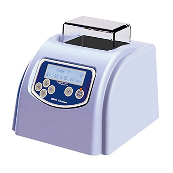
- Page 1 Mini Cooling Dry Bath Incubator (Mini Cooler) Instruction Manual Catalog No. MC-0203 (programmable cooling and heating capability) www.majorsci.com service@majorsci.com Version 03C Revised on : 2018/3/1...
-
Page 2: Packing List
-1x Instruction Manual Signed by: Date: Major Science is liable for all missing or damaged parts / accessories within 7 days after customer received this instrument package. Please contact Major Science immediately regarding this issue. If no response within such time period from consignee party, that will be consignee... -
Page 3: Table Of Contents
Packing list ......................1 Warning ....................... 4 Section 1 Introduction ..................9 Section 2 Product Specifications ..............11 Section 3 Installation Instructions ..............13 Section 4 Device Operation Instructions ............14 Controls and Features ................14 Turn On the Instrument ................. 16 Setting Calendar ................... - Page 4 Temperature Calibration ............... 49 Section 8 Ordering information ............... 52 Section 9 Warranty ................... 53...
-
Page 5: Warning
Warning Major Science Mini cooler Incubator has been tested and found to comply with safety limits for the CE regulation. Also, Mini cooler Incubator is RoHS compliant to deliver confident product which meets the environmental directive. These limits are designed to provide reasonable protection against harmful interference when the equipment is operated in a commercial environment. - Page 6 12. The instrument is intended for scientific research use only, and must be operated by qualified personnel who realize the potential risks of the use of this instrument. Major Science makes no claim that its instruments are designed or certified as medical device; no representation, promises, express warranty, or implied warranty will be made concerning the suitability of these instruments for any medical use.
- Page 7 To avoid electrical shock: 1. In the event of solution accidentally spilled into the instrument, it must be dried out for a period of time, at least 2 hours, and restored to NORMAL CONDITION before each operation. 2. NEVER connect or disconnect wire leads from the power jacks when the power is on.
- Page 8 Battery Replacement Notice The product may contain an internal manganese dioxide. There is risk of fire and burns if the battery pack is not handled properly. To reduce the risk of personal injury: 1. Do not attempt to recharge the battery. 2.
- Page 9 Aluminum block drop Power cord plug wrong 2. Preventative measures of risk Potential Risk Preventive measures Bruise Do not put the machine near the table edge. Burn Cover the lid or wear insulated gloves. Cover the lid to avoid spray water or wear insulated Scald gloves.
-
Page 10: Section 1 Introduction
Section 1 Introduction The mini cooler 200 series is designed to meet the requirement of accurate temperature control, ease of data transferring and programming, small foot print and ease of use. Mini cooler is capable of setting temperature between 100 C to -10 C depending on your application and usage. - Page 11 Astounding heating and cooling rate for different application Small voltage consumption for low electricity consumption Variety sizes of aluminum alloy block for selection and customization USB and Bluetooth port for easy data logging, transfer and modification Optional car adaptor provides portability on the go Blocks interchangeable with mini- dry bath...
-
Page 12: Section 2 Product Specifications
Section 2 Product Specifications Display Maximum Heating / Cooling Power Controller High performance Microprocessor Dimension L152 x W135 x H185mm Temperature Control Range 30°C below ambient temperature ( minimum -10°C) to 100°C. Temperature Increment / 0.1°C Decrement Temperature Calibration 0.2°C @ 37°C Temperature Uniformity 0.25°C @ 37°C Temperature Accuracy... - Page 13 Leakage proof for heating chamber Safety Device Over Temperature protection Rated Voltages AC input 100V - 240V~; 2A, 50/60 Hz DC input: +12V / 5A, 60W max. Approx. 1.3 kg Weight Feature USB for data logger and control Transparent Lid Computer/laptop recommended specification 1.8GHz Pentium®...
-
Page 14: Section 3 Installation Instructions
Section 3 Installation Instructions The Mini cooler Incubator is actually a pre-installed instrument. As long as it is placed on a sturdy and level surface in a safe, dry place, and is inserted with one or two heating aluminum block(s) or simply water as a water bath, it is ready for operation. -
Page 15: Section 4 Device Operation Instructions
Section 4 Device Operation Instructions Controls and Features Please refer to below figures on the following page for the location of the different keys. Front panel Back panel Start / Stop: Active and stop operation of the device. Enter: Enable the alteration of a selected value. - Page 16 Up: To increase temperature value or time value. Down: To decrease temperature value or time value. Left: Move cursor to the left. Return to previous step under the operation mode. Right: Move cursor to the right. AC Power Switch: The main power switch. Press “ ”...
-
Page 17: Turn On The Instrument
Turn On the Instrument 1. Place Programmable Mini cooler Incubator on a sturdy, level surface in a safe, dry place away from laboratory traffic. 2. Ensure that the AC power switch is OFF, and then plug the three-pronged power cord into a grounded three-prong AC outlet of the appropriate voltage. 3. -
Page 18: Setting Calendar
Setting Calendar 1. Please switch the main power ON and press key simultaneously until the display 1600 (range is: 1500~2000) appeared which is located on the up left area of display shown as below. And then release them immediately. 2. The Calendar Setting Screen is displayed. The parameters on the screen are flashing, and then use key and key to move cursor to... -
Page 20: Operation Mode: Quick Start Mode
Operation Mode: Quick Start Mode 1. Switch the main power ON. 2. Use key and key to select “Quick Start” icon, then press key to enter next screen. 3. There are 5 modes of “Quick Start”. Use key and key to select the mode that you want, and then press key to store the upsated value. - Page 21 Note (1): When running Quick Start Mode, the current temperature of block and the step settings will show on the screen. The running time works in only one situation - starts counting up once reaching the set temperature. Press key to display the set temperature and time. It will be kept on screen for 5 seconds or just press key again to go back monitor screen immediately.
-
Page 22: Operation Mode: Constant Mode
Operation Mode: Constant Mode 1. Switch the main power ON. 2. Use key and key to select “Constant Mode” icon, then press key to enter next screen. 3. Press key make the parameter become flashing, then use key and key to move cursor to the parameter. Use key and key to adjust the setting value, then press key to store the... - Page 23 6. Press again to stop the device. A confirm page will pop out, select “YES” to leave the mode Note (2): When running Constant Mode, the current temperature of block and the step settings will show on the screen. There are two situations for running time: Case 1: set time is zero, it will run continuously.
-
Page 24: Operation Mode: Programmable Mode
Operation Mode: Programmable Mode 1. Switch the main power ON. 2. Use key and key to select “Programmable Mode” icon, then press key to enter next screen. 3. Press key and then use key and key to set program number (It can maximum save 10 file from 0 ~ 9). Press key again to store the program number. - Page 25 6. Press key to next screen. Repeat operating step 4~6 to set Programmable Mode Step 1-3. 7. Press key and then use key and key to increase or decrease value for cycle times (up to 9 cycles), then press key to store the updated value.
- Page 26 Note (2): When running Programmable Mode, the current temperature of block and the step settings will show on the screen. You can set up all 4 steps, or, for example, if you only need 3 steps (Step0 – Step2) in the program, set the running time in Step3 at 0 (zero). Then when the program finishes Step2, it will return to the first step or stop the temperature control (i.e., gradually return to the ambient temperature), depending on the numbers of cycles you set.
- Page 27 Press key to display the set temperature and time. It will be kept on screen for 5 seconds or just press key again to go back monitor screen immediately.
-
Page 28: Operation Mode: Annealing Program
Operation Mode: Annealing Program 1. Switch the main power ON. 2. Use key and key to select “Annealing Program” icon, then press key to enter next screen. 3. Use and then press key and key to move cursor to the parameter. Use key and key to change the parameter. - Page 29 5. Use and then press key and key to move cursor to the parameter. Use key and key to change the parameter. Press key to store the updated value and use to enter next screen. Press key return to select operation mode page. c.
- Page 30 Note (1): When running Annealing Program Mode, the current temperature of block and the step settings will show on the screen There are two situations for running time: Case 1: set time is zero. Once the current block temperature reaches the set temperature, it will go to the next step immediately.
-
Page 31: Operation Mode: Setting Device Number
Operation Mode: Setting Device Number 1. Switch the main power ON. 2. Use key and key to select “Device Number” icon, then press key make the parameter become flashing. .Use key to change the step parameter then press key to store the updated value (Device Number range is 1~99). -
Page 32: Section 5 Installation Software Instructions
Section 5 Installation Software Instructions *To start install the program, please log in as an administrator on the computer. Please refer to the Web link to change the account of computer: a. For Windows® XP http://www.microsoft.com/resources/documentation/windows/xp/all/proddocs/en-us/windows _security_runas.mspx?mfr=true b. For Windows® 7 http://windows.microsoft.com/en-hk/windows7/installing-programs-frequently-asked-questio For Windows®... - Page 33 Step2. Check computer system type. Step3. Install Mini cooler multi-device control software. Note: Six files are included in the software disk. Please install the corresponding software based on your computer system type. System type A. 64 bit : use “VCP_V1.3.1_Setup_x64” (as box 1) System type B.
- Page 34 Step4. Click “next” to start installs the program. Step5. Click “Next” to start installs the device in order to work program.
- Page 35 Step6. Complete the installation program.
-
Page 36: Install Mini Cooler View Chart Software
5.2 Install Mini cooler view chart software Step1. Select MC-02 setup program. Step2. Install MC-02 setup program. - Page 37 Step3. Accept the license agreement and then press the “Next” to proceed. Step4. Save this program in your specifying location then press “Next” to proceed.
- Page 38 Step5. Click “Next” to begin the installation. Step6. Press “Close” to complete the program installation.
- Page 39 Step7. The short paths will be shown on desktop. Double click on MC-02 icon to open the software.
-
Page 40: Section 6 Function Control Software Instructions
Section 6 Function Control Software Instructions 6.1 Temperature Monitoring Chart (1)~(4) (5)~(11) (27) (12)~(26) System Setup Function Option Setting: Set up the file name format and record period. ReScan Device: Detect the connection of device. About Information: MC-02 software version and patent information. - Page 41 Device Number: Set device number (range: 1 – 99). Link Status: The connection status of the device. Green light means the device is detected, while red light stands for disconnection or the device is undetected. (1) Option Setting: Set the file name format (2) About Information...
- Page 42 Operation Mode: Quick Start: There are 5 default modes, to select the mode by scrollbar. Constant Mode: There are setting parameters for Temp. and Time. Programmable Mode: From Program 0 to Program 9, 10 programs for setting. To select the mode by scrollbar.
- Page 43 Run / Stop Function: Run: To start the operation mode. Exit: To exit this software. Temperature Curve Display Temp. SV curve: The color of temperature set value curve is white. Temp. PV curve: The color of temperature real value curve is red. Temperature / Time Function The set temperature value.
- Page 44 To set the maximum temperature value on the chart. To set the minimum time value on the chart. To set the maximum time value on the chart. Time Function To show a part of time on the chart. To show the current trend of the temperature. Data Function To reset all chart option parameters.
-
Page 45: Operation Mode Setting Table
6.2 Operation Mode Setting Table (2)~(5) (6)~(7) (8)~(10) Program Mode There are 4 setting steps, from step 0 to step 3 for temperature (Temp.) and operation time (Time) setting, and also setting for Cycle Times. - Page 46 Annealing Program To set the initial temperature value. To set descending temperature value. To set holding time value. To set final temperature value. Constant Mode To set the target temperature value of constant mode. To set the target time value of constant mode. Time unit / Upload or Download Data All set time parameters unit is minute.
-
Page 47: View History
6.3 View History (1)~(14) (15) Temperature Curve Display Temp. SV curve: The color of temperature set value curve is white. Temp. PV curve: The color of temperature real value curve is red. History Data To view historic record data. To download the historical data from Mini cooler to computer. - Page 48 Chart Option Function To set the minimum temperature value on the chart. To set the maximum temperature value on the chart. To set the minimum time value on the chart. To set the maximum time value on the chart. Time Function To show a period of 20 minutes/seconds of the curve on the chart.
-
Page 49: Section 7 Troubleshooting Guide
Section 7 Troubleshooting Guide Many operating problems may be solved by carefully reading and following the instructions in this manual accordingly. Some suggestions for troubleshooting are given below. Should these suggestions not resolve the problem, contact our SERVICE DEPARTMENT or a distributor in your region for assistance. If troubleshooting service is required, please include a full description of the problem. - Page 50 7.3 Temperature Calibration Mini Cooler with the optional block has been calibrated as a set. But, the different kinds of block, whose T are not the same result different influences. For optimum accuracy temperature control or while changing with different kinds of block, Mini Cooler should be calibrated in accordance with the procedure outlined below.
- Page 51 (Start calibration) (Arrival the target temperature) (Key in the same value as thermometer) 4. Use key and key to adjust the T value (temperature range is -5 The device will start cooling from 0 to -5 when temperature arrival -5 and then to start countdown from 30 min to 0 min.
- Page 52 is 37 The device will start heating from -5 to 100 when temperature arrival 100 and then to start countdown from 30 min to 0 min. The device will alarm “beep” while T and 0 min. T value is flashing, and then use key and key to enter the real temperature as...
- Page 53 Section 8 Ordering information Cat. No. Description MC-0203 Mini Cooling Dry Bath Incubator, 200 series, programmable cooling and heating capability, without block ACCESSORIES MD-MINI-B01 For 0.2ml tube(PCR Strip tube), ø 6.35mm, 32 wells, L71xW47xH32, Depth 19mm MD-MINI-B02 For 1.5ml tube, ø 10.8mm, 12 wells, L71xW47xH32mm, Depth 28.5mm...
- Page 54 All claims made under this warranty must be presented to Major Science within one year following the date of delivery of the product to the customer.
- Page 55 MEMO...
- Page 56 MEMO...
- Page 57 MEMO...
- Page 58 MEMO...
Need help?
Do you have a question about the MC-0203 and is the answer not in the manual?
Questions and answers