Table of Contents
Advertisement
Quick Links
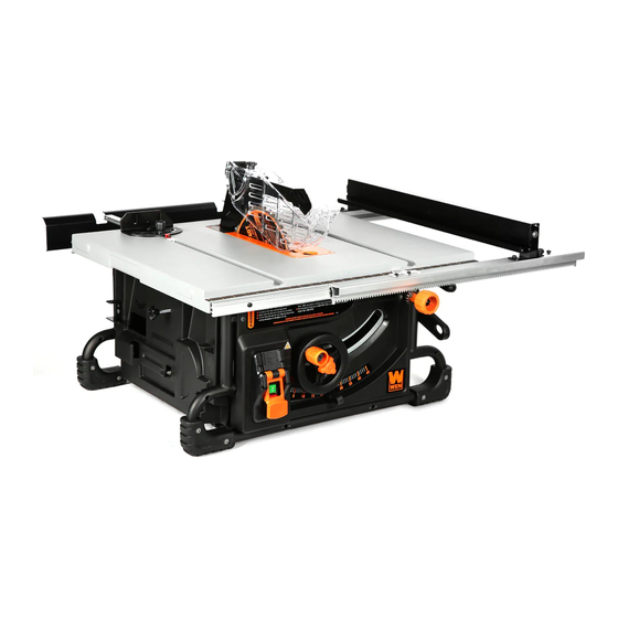
MODEL TT1015
10-INCH BENCHTOP
TABLE SAW
Instruction Manual
NEED HELP? CONTACT US!
Have product questions? Need technical support? Please feel free to contact us:
1-800-232-1195 (M-F 8AM-5PM CST)
TECHSUPPORT@WENPRODUCTS.COM
IMPORTANT: Your new tool has been engineered and manufactured to WEN's highest standards for dependability,
ease of operation, and operator safety. When properly cared for, this product will supply you years of rugged,
trouble-free performance. Pay close attention to the rules for safe operation, warnings, and cautions. If you use
your tool properly and for its intended purpose, you will enjoy years of safe, reliable service.
WENPRODUCTS.COM
For replacement parts and the most up-to-date instruction manuals, visit
Advertisement
Table of Contents

Related Manuals for Wen TT1015


Summary of Contents for Wen TT1015
- Page 1 1-800-232-1195 (M-F 8AM-5PM CST) TECHSUPPORT@WENPRODUCTS.COM IMPORTANT: Your new tool has been engineered and manufactured to WEN’s highest standards for dependability, ease of operation, and operator safety. When properly cared for, this product will supply you years of rugged, trouble-free performance. Pay close attention to the rules for safe operation, warnings, and cautions. If you use your tool properly and for its intended purpose, you will enjoy years of safe, reliable service.
-
Page 2: Table Of Contents
To purchase accessories for your tool, visit 10-Inch Benchtop Table Saw Rolling Stand (Model TT1088) 8-inch Dado Blade Set (Model BL088D) Zero Clearance Dado Insert (Model TT1015-DADO) 10-Inch Saw Blades (Models BL1012, BL1024, BL1024C, BL1028, BL1032-2, BL1040, BL1040C, BL1060, BL1060C, BL1080, BL1080C) -
Page 3: Welcome
INTRODUCTION Thanks for purchasing the WEN Table Saw. We know you are excited to put your tool to work, but first, please take a moment to read through the manual. Safe operation of this tool requires that you read and understand this operator’s manual and all the labels affixed to the tool. -
Page 4: Safety
GENERAL SAFETY RULES WARNING! Read all safety warnings and all instructions. Failure to follow the warnings and instructions may result in electric shock, fire and/or serious injury. Safety is a combination of common sense, staying alert and knowing how your item works. The term “power tool” in the warnings refers to your mains-operated (corded) power tool or battery-operated (cordless) power tool. - Page 5 GENERAL SAFETY RULES WARNING! Read all safety warnings and all instructions. Failure to follow the warnings and instructions may result in electric shock, fire and/or serious injury. Safety is a combination of common sense, staying alert and knowing how your item works. The term “power tool” in the warnings refers to your mains-operated (corded) power tool or battery-operated (cordless) power tool.
-
Page 6: Specific Rules For Your Table Saw
SPECIFIC RULES FOR YOUR TABLE SAW WARNING! Do not operate the power tool until you have read and understood the following instructions and the warning labels. TABLE SAW SAFETY 14. MAKE WORKSHOP KID PROOF with padlocks, mas- ter switches, or by removing starter keys. 1. - Page 7 SPECIFIC RULES FOR YOUR TABLE SAW WARNING! Do not operate the power tool until you have read and understood the following instructions and the warning labels. 3. Never use damaged or deformed saw blades. Only 6. For the riving knife and anti-kickback device to work, use sharp blades.
- Page 8 SPECIFIC RULES FOR YOUR TABLE SAW WARNING! Do not operate the power tool until you have read and understood the following instructions and the warning labels. 6. Never use a damaged or cut push stick. It may break 1. Never stand directly in line with the saw blade. Al- causing your hand to slip into the saw blade.
- Page 9 SPECIFIC RULES FOR YOUR TABLE SAW WARNING! Do not operate the power tool until you have read and understood the following instructions and the warning labels. 10. When restarting the saw with the saw blade in the 8. Never use damaged or incorrect saw blade mount- workpiece, center the saw blade in the kerf so that the ing means such as flanges, saw blade washers, bolts or saw teeth are not engaged in the material.
-
Page 10: Electrical Information
ELECTRICAL INFORMATION DOUBLE-INSULATED TOOLS The tool’s electrical system is double insulated where two systems of insulation are provided. This eliminates the need for the usual three-wire grounded power cord. Double insulated tools do not need to be grounded, nor should a means for grounding be added to the product. All exposed metal parts are isolated from the internal metal motor components with protecting insulation. -
Page 11: Before Operating
UNPACKING & PACKING LIST WARNING! Do not plug in or turn on the tool until it is fully assembled according to the instructions. Failure to follow the safety instructions may result in serious personal injury. UNPACKING With the help of a friend or trustworthy foe, carefully remove the table saw from the packaging. Make sure to take out all contents and accessories. -
Page 12: Know Your Table Saw
TOOL PURPOSE Make smooth, straight cuts easily with your WEN Table Saw. Refer to the following diagrams to become familiar- ized with all the parts and controls of your table saw. The components will be referred to later in the manual for assembly and operation instructions. -
Page 13: Assembly
ASSEMBLY WARNING! Do not plug in or turn on the tool until it is fully assembled according to the instructions. Read through and become familiarized with the following procedures of handling and adjusting your tool. Failure to follow the safety instructions may result in serious personal injury. INSTALLING THE FENCE Fig. - Page 14 ASSEMBLY INSTALLING THE TABLE EXTENSION Fig. 5 1. Use a Phillips-head screwdriver (not included) to attach the table extension rods (Fig. 5 - 1) to the table extension (Fig. 5 - 2) with the M6x10 screws and 6mm washers. 2. Loosen both knobs (Fig. 6 - 1) on the rear side of the saw and insert the extension rods into the holes.
- Page 15 ASSEMBLY INSTALLING THE BLADE GUARD Fig. 8 WARNING! Disconnect the machine from the power source before performing the following steps. 1. Remove the table insert (Fig. 8 - 1) by turning the lock knob (Fig. 8 - 2) 1/4 turn. Lift the insert out of the table (Fig.
-
Page 16: Operation & Maintenance
ASSEMBLY DUST COLLECTION Fig. 13 1. Attach a 2½” dust hose (not included) to the dust port (Fig. 13 - 1). 2. Secure the hose with a hose clamp (not included). Make sure the hose is attached to the dust port tightly. CAUTION: Always use dust collection when operating the machine. - Page 17 OPERATION BEVELING THE BLADE Fig. 16 To bevel the blade, move the blade bevel locking lever (Fig. 16 - 1) up to release the locking mechanism. Adjust the blade bevel using the pointer (Fig. 16 - 2) and scale. Once the blade is in the desired position, lock the blade in place by moving the blade bevel locking lever down.
- Page 18 OPERATION MITER GAUGE Fig. 21 The miter gauge can be positioned on either side of the blade, as shown in Fig. 21. To change the angle, loosen the knob on the gauge (Fig. 22 - 1) and set it to the desired angle, then tighten the knob.
- Page 19 OPERATION REPLACING THE SAW BLADE Fig. 24 WARNING! The blade is very sharp. Wear cut-proof Arbor Lock gloves when handling the blade. 1. Remove the blade guard assembly. See page 11. 2. Raise the blade all the way up, and remove the table insert.
- Page 20 OPERATION WARNING! Serious injury can be caused by kickback. Kickback can occur when tension is created between a workpiece sitting against the fence and the blade. This can cause the workpiece to be thrown toward the operator or bystanders. To prevent kickback, review the "SPECIFIC RULES FOR YOUR TABLE SAW" section. CROSSCUTTING Fig.
- Page 21 OPERATION Fig. 28 WARNING! Disconnect the machine from the power source before performing the following steps. WARNING! Keep both hands away from the blade and the path of the blade. BEVEL CROSSCUTTING Bevel Crosscutting is to cut a workpiece across its main grain or its width with an angle other than 0°.
- Page 22 OPERATION BEVEL RIPPING Fig. 29 Bevel ripping is to cut a workpiece along its main grain or its length with an angle other than 0. This operation is same as ripping, except that the rip cut is at an angle. Fol- low the steps below to make a bevel rip cut.
- Page 23 OPERATION MITERING A miter cut is the same operation as crosscut except the miter gauge is set at an angle other than 90°. 1. Remove the fence. 2. Set the blade at 0 bevel angle (see page 17, "BEVELING THE BLADE"). 3.
- Page 24 Specialized dado blades are also available as aftermarket accessories, as are specialized throat plates compatible with such dado blades. WEN offers a dado blade set (model BL088D) and dado throat plate (model TT1015-DADO), available for purchase at wenproducts.com. CAUTION! Use extreme caution when dado cutting. Always check dado blade clearance before connecting the saw to a power source.
-
Page 25: Adjustments
ADJUSTMENTS RIVING KNIFE & SAW BLADE ALIGNMENT WARNING! Disconnect the machine from the power source before performing the following steps. The riving knife and saw blade alignment has been adjusted at the factory. In most cases, there should not be ad- justments needed. - Page 26 ADJUSTMENTS RIVING KNIFE & SAW BLADE ALIGNMENT (CONT.) 13. Reinstall the table insert. 14. Reinstall the blade guard assembly. Fig. 35 FENCE AND SAW BLADE ALIGNMENT WARNING! Disconnect the machine from the power Saw Blade Fence source before performing the following steps. WARNING! Fence and saw blade must align in order to reduce the risk of kickback during operation.
- Page 27 ADJUSTMENTS MITER GAUGE SLOT AND BLADE ALIGNMENT Fig. 37 For the best results, the miter slot should be adjusted parallel to the blade. This is done at the factory, but if it is not exactly parallel, fol- low the steps below to reduce the risk of kickback. WARNING! Disconnect the machine from the power source before performing the following steps.
- Page 28 ADJUSTMENTS BEVEL STOP ADJUSTMENT Fig. 39 The bevel stops have been set at the factory, and should not require adjustments. However, if your cuts are noticeably inaccurate, follow the steps below to adjust the bevel. Saw Blade 90º Square WARNING! Disconnect the machine from the power source before performing the following steps.
- Page 29 ADJUSTMENTS LEVELING TABLE INSERT Leveling Fig. 42 The table insert must sit flush with the table in order to provide a Screws smooth surface to slide the finished workpiece on. To check and Straight adjust the table insert, follow the steps below. Edge WARNING! Disconnect the machine from the power source before performing the following steps.
-
Page 30: Maintenance
WARNING! Any attempt to repair or replace electrical parts on this tool may be hazardous. Servicing of the tool must be performed by a qualified technician. When servicing, use only identical WEN replacement parts. Use of other parts may be hazardous or induce product failure. - Page 31 MAINTENANCE STORAGE Fig. 45 1. Store the tool in a clean and dry place away from the reach of chil- dren. Store in temperatures between 41° to 86°F. 2. Cover the table saw in order to protect it from dust and moisture. It is preferable to store it in its original packaging with the instruction manual.
-
Page 32: Troubleshooting Guide
2. Consult extension cord chart on p. 10. cord. Machine will not start. 3. Worn carbon brushes. 3. Replace carbon brushes. 4. Consult WEN customer service at 1(800) 232- 4. Faulty power cord, motor, or switch. 1195. Blade does not 1. Blade arbor nut not 1. -
Page 33: Exploded View & Parts List
EXPLODED VIEW & PARTS LIST NOTE: Not all parts may be available for purchase. Parts and accessories that wear down over the course of normal use are not covered under the warranty. - Page 34 EXPLODED VIEW & PARTS LIST Part No. Description Qty. Part No. Description Qty. Blade Guard Socket Head Cap TT1015-001ASM Assembly Screw with Lock Washer & Flat TT1015-002ASM Fence Assembly Washer, M5x12 Table Insert TT1015-003 Phillips Head Assembly Screw with Lock Table Insert Washer &...
- Page 35 Lock Washer, Spring Pin, M5x12 4x25mm Blade, 10", 40T, Bushing BL1040 5/8" Arbor, 1.6mm Worm Gear Thickness Cap Screw, M5x10 TT1015-087 Blade Flange Spring Blade Nut, 5/8"-12 TT1015-088 Double Pitch Rear Cover Right Cover Spindle Lock Spring Phillips Head Screw with Flat...
- Page 36 Part No. Description Qty. Part No. Description Qty. Extension Wing Phillips Head Assembly Screw, M5x40 Miter Gauge TT1015-114 Push Stick TT1015-095 Assembly TT1015-115 Blade Wrench Fence Mounting Right Cover Panel Knob, M6 Switch Stop Plate Lock Nut, M6 Switch Lock Plate Self-Tapping Screw M5-2.12x12...
-
Page 37: Warranty Statement
(2) years from date of purchase or 500 hours of use; whichever comes first. Ninety days for all WEN products if the tool is used for pro- fessional or commercial use. - Page 38 NOTES...
- Page 39 NOTES...
- Page 40 THANKS FOR REMEMBERING V. 2021.12.20...
Need help?
Do you have a question about the TT1015 and is the answer not in the manual?
Questions and answers