
Related Manuals for MK Martin Meteor 54


Summary of Contents for MK Martin Meteor 54
- Page 1 54-60 Meteor Snowblower Operator’s / Parts Manual MK Martin Enterprise Inc. 3950 Steffl er Rd Elmira, ON, Canada N3B 2Z3 Tel: 519-664-2752 Toll Free: 1-855-664-2752 Fax: 519-664-3695 E-mail: sales@mkmartin.ca www.mkmartin.ca Rev:17-6...
-
Page 3: Table Of Contents
Table of Contents • Warranty ......................• Regisration Page ...................... • Safety ........................• Decal Location ....................• Assembly ......................• Operation ......................12-13 • Main Blower Parts ....................14-15 • Shearbolt ....................... • Hydraulic Chute Rotator Installation ..............16-17 •... -
Page 4: Warranty
Warranty coverage is null and void unless the Warranty Registration form has been completed in full and is on fi le at MK Martin Enterprise Inc. Warranty begins at the time of customer delivery and is activated upon Warranty Registration receipt at MK Martin Enterprise Inc. -
Page 5: Regisration Page
M K Martin Enterprise Inc 3950 Steffl er Rd Elmira ON CA N3B 2Z3 --------------------------------------------------------------------------------------------------------------------- Purchaser’s warranty protection is valid only when this completed form or a copy of this form is on fi le at M K Martin Enterprise Inc. By fi lling out this form the purchaser has acknowledged delivery of equipment and owner’s / operator’s manual and has accepted the condition of the equipment. - Page 6 Warranty Registration Please Cut and Return to M K Martin Enterprise Inc Fold And Tape here Do not tape all edges or use staples Fold Here ------------------------------------------------------------------------------------------------------------------------- Postage Stamp M K Martin Enterprise Inc 3950 Steffl er Rd Elmira ON CA N3B 2Z3...
-
Page 7: Safety
Safety Take Note! This safety symbol is found throughout this manual to call your attention to instruc- tions involving yourself and others working around the machine. • Failure to follow these instructions can result in injury or death This symbol means -- Attention! -- Become Alert! -- Your Safety is involved! - Page 8 Safety -- It’s in your interest. Safety Guidelines Safety of operation is one of our main concerns, however it is up to the operator to practice caution. To avoid personal injury, study the following precautions and insist that those working with you follow them.
- Page 9 Hydraulic Leak Test Warning! Do not check for high pressure leaks with your hands or fi ngers. Use a piece of cardboard or a thin piece of wood to detect the leak. A high pressure stream of fl uid from a pin hole can penetrate the skin and inject hydraulic fl uid into your blood veins.
-
Page 10: Decal Location
S:\Solidworks\Solidworks_Elo\Snowblower\78 Meteor\78 Main Assy.SLDASM Meteor Snowblower Decal Location 54-60 1- 212 Do not open or remove safety shields 7- 226 Shut off engine and remove key while engine is running. before performing maintenance or repair 1 piece work. 1 piece Folder Notes S:\Solidworks\Solidworks_Elo\Snowblower\78 Meteor\... -
Page 11: Assembly
Meteor Snowblower Hand Crank Assembly Information Upon receiving the Meteor Blower The blowers are shipped in a packaged state Carefully remove the chute and PTO shaft from the area of the auger and set them aside. Lo- cate the bag or package of small components. Remove the ties that hold the plastic ring on the blower, apply a light coat of grease to both sides of ring and replace. -
Page 12: Operation
54-60 Meteor® Snowblower This Blower is ideal for small tractors 15-20 HP Cat #1 3PH. Attaching the Meteor® Blower for the fi rst time. 1. Set the blower on a level surface and back the tractor up to it. Place the lower 3PH arms of the tractor between the lower hitch plates on the blower and insert the hitch pins that came with the blower, secure these with the Lynch Pins. - Page 13 Operating the Meteor® Snowblower This blower is on the back of the tractor facing toward the rear. While blowing snow the tractor has to be backed into the snow. Stay in the seat of the tractor all the time that the blower is running. Make sure the area is clear of people while blowing snow.
-
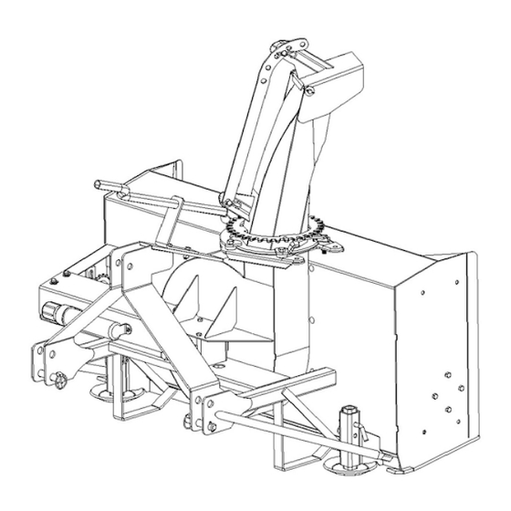
Page 14: Main Blower Parts
54-60 Snowblower Parts Item # 54 Part # 60 Part # Description 23897 23898 Main Body Bolt 7/16x1 1/2 c/w lw, n Bent Pin 1/2” 21569 21569 Adjustable Skid Shoe 519-752096 519-752096 Hitch Pin Lynch Pin T281-1 3/8 T281-1 3/8 Gearbox 519-51118708C 519-51118708C... -
Page 15: Shearbolt
54-60 Snowblower Parts Item # 54 Part # 60 Part # Description Carriage Bolt 5/16x3/4 c/w lw 519-511174 519-511174 Bearing Flange 519-511175 519-511175 Bearing 519-513025 519-513029 Shear Sprocket Auger Shear Bolt 1/4x1 #2 c/w in 33179 519-60118408C Auger Drive Shaft Bolt 5/8x4 c/w lw, n 10730 10730... -
Page 16: Hydraulic Chute Rotator Installation
Motor Hydraulic Rotator Installation The Hydraulic Chute Rotator uses a hydraulic motor, controlled by the tractor hydraulics to ro- tate the chute. The kit includes a safety shield, 2 pcs 1/2-20 UNF bolts, hydraulic fi ttings, hoses and tractor couplings. When installing the hydraulic elbows, turn them in “no more than 4 rounds”... - Page 17 Motor Hydraulic Rotator Installation Installing the Hydraulic Chute Rotator Safety Shield with Hose Guide The Hydraulic Chute Rotator has rods that act as guides to guide the Defl ector Hydraulic Hose (if used) to the outside of the shield. All Shields are manufactured with the Rods straight. They may need to be bent in or out for smaller or larger blowers.
-
Page 18: Hydraulic Chute Rotator Parts
Hydraulic Chute Rotator Parts Item # Part # Description 23931 Shield Bolt 1/2-20x2 c/w lw, n 519-511706 Small Gear Bolt 3/8x1 c/w lw 519-511703 Motor Bracket 519-511704 Motor 519-511705 Crossover Relief Valve S71-4 Tractor Adapter 23895 Hydraulic Hose 519-9515-10-6 Hydraulic Elbow Socket Head Cap Screw 5/16x1 1/2 (O Ring 3/32x.75id Note*... -
Page 19: Electric Chute Rotator Installation
Electric Chute Rotator Installation Instructions 1. Replace The 2 hole Chute Clamp with the appropriate washer. (54-68 has 1/2” hole, 75- has 5/8” hole. Please Note: the chute bearing is between 2 washers. An SAE Washer on bottom and a thin Wave Washer on top 2. - Page 20 Modifi ed 2 button 12 Volt Winch Control Installation Modifi ed Control handle Wire to Battery Wire to Motor 2 Wire Connector Installing Remote Control Cable 1. Refer to page 5 in Superwinch® Owner’s Guide and note the wire to the battery. The inline breaker is to protect the primary wires and the handle circuit.
- Page 21 Electric Rotator Control Handle Installation R e p l a c e a b l e ATO style 20 Amp Breaker 2 Prong Flat Trailer Connector May not be as shown To Rotator Motor From Battery See SuperWinch Owners Guide for Instructions for battery hookup. Use the 50 amp breaker as shown to protect the primary wires in case of a short circuit.
-
Page 22: 46-75 Electric Chute Rotator Parts
46-75 Electric Chute Rotator Parts Item # Part # Description 519-6232053 Motor Connector 23589 Control Handle 10581 Control-Motor Wire Bolt 5/16x1 c/w lw,fw Bolt 1/2x1 c/w lw,fw, n Bolt 5/16x1 c/w lw, n 10669 Rotator Base Bolt 1/2x1 1/2 c/w lw, n 51376 Small Gear Modifi ed 23612... -
Page 24: Pto Parts
Comer T20 PTO Item # Description Part # Complete Collar Yoke 141.022.324.1 Cross Journal Assy 180.012.130 Complete Shear Yoke 143.220.003.1 Guard Retaining Collar for Outer Tube 8180.012.184 Special Plastic Bolt 8180.014.240 Guard Retaining Collar for Inner Tube 8180.012.183 Safety Chain 180.016.790 Complete Guard with Instruction Manual 142.220.252.7221... -
Page 25: Gearbox Parts
T 281 J 54-60 Meteor Gearbox T 281 J 68 Meteor Gearbox Item# Part # Description 519-02814208 Output shaft 1 3/8” Z6 519-87300028 Oil Seal 35x52x7 519-80100870 Ball Bearing 6207 35x52x17 519-02597500 Shim Kit 35x3x48 519-02595020 Crown Gear Z18 M5 519-84100232 Key 10x8x25 519-02812212... -
Page 26: Pto Instructions
PTO Installation Instructions for Snowblower... - Page 27 PTO Installation Instructions for Snowblower For Better PTO Shaft and Gearbox Operation A proper initial installation will give you years of satisfactory service on your equipment. Please read carefully, following instructions which have been specially made to help you and make you satisfied with your purchase.
- Page 28 Previous examples clearly demonstrate that universal joint angle is directly related with life of the PTO. In order to reduce angle, it is necessary to increase the distance between snowblower and tractor. Too Large Angles at PTO Joints Reasonable Angles at PTO Joints To Avoid Acceptable If it is impossible to increase the distance between snowblower and tractor, in order to maintain a...
- Page 29 Shear Bolts Shear bolts are built to break under shock loads on the fan or auger. However under certain circumstances this security is not adequate. Example: a sudden high impact shock on the fan may, in some cases break the fan shaft without breaking the shear bolt. If the shear bolt breaks, make sure to always replace it with the same grade of bolt (grade 5 for PTO series 20-40-50-60, and grade 8 for PTO series 80) it is necessary to always maintain this bolt very tight in order to keep the efficiency of the shearing mechanism.
- Page 30 Effective PTO Drive Shaft Maintenance...
- Page 31 Avoidable Damage Possible Causes Corrective Actions Quick-disconnect yoke Quick-disconnect pin tight or Quick-disconnect pin Clean, oil and follow completely seized dirty (insufficient service instruction Quick-disconnect pin damaged maintenance) Replace Quick- (broken or bent) disconnect pin Quick-disconnect pin damaged Quick-disconnect pin Shorten shaft length in locking position defective (forced into...
- Page 32 Avoidable Damages Possible Causes Corrective Actions Cross Arms broken Extreme torque peak or Use appropriate safety Cross Kit shock load device Change to a larger PTO size Axial loads too large Shorten PTO shaft Replace defective cross bearings Bearing caps turning in their Excessive continuous Verify compatibility cross journal...
- Page 33 Avoidable Damages Possible Causes Corrective Actions Excessive wear of shield Insufficient lubrication Follow lubrication Shield bearings instructions Incorrect chain mounting Mount chain to allow maximum angularity Shield interfering with Avoid shield contact with implement machine or tractor Replace shield bearings Chain failure Shield interfering with Avoid shield contact with...
-
Page 34: Maintenance
54-60 Meteor Snowblower Maintenance • Auger Drive Chain Tightener – tighten chain allowing ¼” sag in the bottom span of chain (be- tween drive and driven sprocket). Lubrication • Gearbox- check oil level every 50 hours. Fill to oil level plug (middle of gearbox) with SAE 90 gear oil. -
Page 35: Sign Off Sheet
Sign Off Form M K Martin Enterprise Inc. follows the general Safety Standards specifi ed by the American Society of Agricultural Engineers (ASAE) and the Occupational Health and Safety Administration (OSHA). Anyone who will be operating and/or maintaining the equipment must read and clearly understand ALL Safety Operating and Maintenance instructions presented in this manual. -
Page 36: Notes
NOTES... -
Page 37: Pto Driveline Dimensions Page
PTO Drive-line Dimension The PTO Drive-line as supplied with the machine will need to be checked for the proper length before being put into service. To accommodate the various hitch and tractor confi gurations the supplied shaft may be too long, or in some cases too short. - Page 40 MK Martin Enterprise Inc. 3950 Steffl er Rd Elmira, ON, Canada N3B 2Z3 Tel: 519-664-2752 Toll Free: 1-855-664-2752 Fax: 519-664-3695 E-mail: sales@mkmartin.ca www.mkmartin.ca...
Need help?
Do you have a question about the Meteor 54 and is the answer not in the manual?
Questions and answers