Table of Contents
Advertisement
Quick Links
Advertisement
Table of Contents

Related Manuals for Telestream PRISM MPI


Summary of Contents for Telestream PRISM MPI
- Page 1 PRISM MPI and MPX SDI / IP Waveform Monitor User Manual April 2021 D00010020C...
- Page 2 Telestream shall pay for the return of the product to Customer if the shipment is to a location within the country in which the Telestream service center is located. Customer shall be responsible for paying all shipping charges, duties, taxes, and any other charges for products returned to any other locations.
- Page 3 DEFINITIONS "Telestream" means Telestream, LLC, a Delaware limited liability company, and its Affiliates , or the local Telestream legal entity that is supplying the equipment. "Program" means the Telestream software product (executable program and/or data) enclosed with this Agreement or included within the equipment with which this Agreement is packed.
- Page 4 Title to the Program and all copies thereof, but not the media on which the Program or copies may reside, shall be and remain with Telestream or others for whom Telestream has obtained a respective licensing right. Customer shall pay when due all property...
- Page 5 Telestream. This Agreement and the license granted herein shall be governed by the laws of the state of California. nAll questions regarding this Agreement or the license granted herein should be directed to the nearest Telestream Sales Office. PRISM MPI-MPX User Manual...
- Page 6 PRISM MPI-MPX User Manual...
-
Page 7: Table Of Contents
Contents Important compliance and safety information Preface Getting Started Product description Rackmount MPI Power-on and Power-off Procedures MPX Power-on and Power-off Procedures SFP Module Installation Network Installation MPI Rear Panel Connectors MPX Rear Panel Connectors Display Elements Activity Center Methods of Operation MPI Touchscreen Operation MPX Front-panel Controls Keyboard and Mouse Operation... - Page 8 Configure to Decode Timecode Configure Reference Settings Set and Recall Instrument Presets Manage Trace and Graticule Intensity Set Time and Date Upgrade Instrument Firmware Upgrade Software License Troubleshooting Functions Headphone/Speaker Volume, Balance, Device, and Source Adjustment Capture Application Information Base Instrument Applications Option MP2-IP-MEAS Option MP2-GEN Options MP2-ENG and MP2-QC...
- Page 9 PTP Operational Overview PTP Introduction Five Basic PTP Timing Messages Profiles and Domains One-step and Two-step Operation Multicast, Unicast, and Mixed Communication Modes BMCA Operation Compensating for Causes of Asymmetric Delay PRISM MPI2-25-MPX2-25 User Manual...
- Page 10 PRISM MPI2-25-MPX2-25 User Manual...
-
Page 11: Important Compliance And Safety Information
Measurement, Control, and Laboratory Use - Part 1: General Requirements. Environmental Perchlorate Materials: this product contains one or more type CR lithium batteries. According to the state of California, CR lithium batteries are classified as perchlorate materials and require special handling. www.dtsc.ca.gov/hazardouswaste/perchlorat for additional information. PRISM MPI-MPX User Manual... - Page 12 SLOVENIA, SPAIN, SWEDEN, UNITED KINGDOM, !CELANO, LICHTENSTEIN, NORWAY, SWITZERLAND Declaration of Conformity Marking by the “CE” symbol indicates compliance with the Essential Requirements of the EMC Directive of the European Union 2014/30/EU This equipment meets the following conformance standards: PRISM MPI-MPX User Manual...
- Page 13 PRISM MPI-MPX User Manual...
- Page 14 RoHS 3 Directives 2011 /65/ EU and EU 2015/863 until July 22, 2021. This product does, however, comply with the RoHS 2 Directive 2011/65/EU. Korea Compliance Statement PRISM MPI-MPX User Manual...
- Page 15 Only qualified personnel who are aware of the hazards involved should remove the cover for repair, maintenance, or adjustment. Before use, always check the product with a known source to be sure it is operating correctly. PRISM MPI-MPX User Manual...
- Page 16 Use only specified replacement parts. Do not operate in wet/damp conditions: Be aware that condensation may occur if a unit is moved from a cold to a warm environment. Do not operate in an explosive atmosphere. PRISM MPI-MPX User Manual...
- Page 17 Be sure your work area meets applicable ergonomic standards. Consult with an ergonomics professional to avoid stress injuries. Use only the Telestream rackmount hardware specified for this product. Service Safety Summary The Service safety summary section contains additional information required to safely perform service on the product.
- Page 18 WARNING: To prevent injury or death, power off the instrument and disconnect it from line voltage before cleaning. WARNING: To reduce the risk of fire and shock, ensure that the mains supply voltage fluctuations do not exceed 10% of the operating voltage range. PRISM MPI-MPX User Manual...
- Page 19 Caution: After the instrument has started the upgrade process, DO NOT remove power from the instrument. If you do so, the instrument flash will be corrupted. The instrument will have to be sent to a Telestream factory service center to have the system firmware restored.
-
Page 20: Preface
"How to use instrument menus. Where to find more information The full User Manual, Release Notes, and other information about your product are available for download at www.telestream.net/video/resources.htm. Table 1 lists all the documentation for the PRISM SDI / IP Waveform Monitor. Product documentation... - Page 21 Preface Product documentation PRISM MPI Dual Rack Field Install 071-3725-00x Describes how to install an MPI Cabinet Version 2 Instructions instrument in a 19” equipment rack Installation Instructions using the optional MPI-RACK-MM or MPI-RACK-MW dual rack cabinet. MPX Rackmount Slides...
- Page 22 Preface Resource Contact Information International Web Site: www.telestream.net Distributor Support See the Telestream Web site for your regional authorized Telestream distributor. Telestream Technical Email: techwriter@telestream.net Writers If you have comments or suggestions about improving this document, or other Telestream documents—or if you've discovered an error or omission, please email us.
-
Page 23: Getting Started
Network installation shows you how to set up your instrument on an Ethernet network. PRISM MPI-MPX User Manual... -
Page 24: Product Description
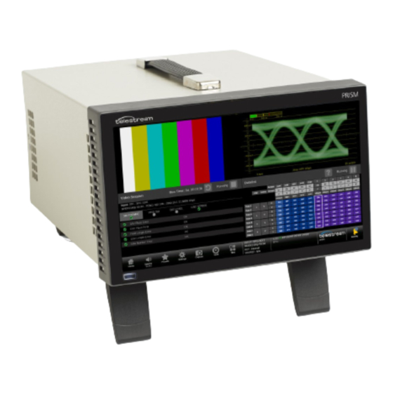
PRISM Model Form Factors The PRISM SDI / IP Waveform Monitor is available in two form factors: The PRISM MPI is 3RU half-rack width with integrated 9-inch HD display and touch panel. Option PHY is available to add physical layer measurement sets. - Page 25 Monitor PTP trend graphs to ensure proper IP system setup for robust sync system • Telestream patented Timing display, the SDI versus Analog reference and ST2022-6 / ST2110-20 / SDI / Analog reference versus PTP reference makes facility timing easy •...
- Page 26 50/59.94/60p Base instrument 3G-SDI Level B 1920x1080 4:2:2 YCbCr 50/59.94/60p Base instrument Quad Link HD-SDI 3840x2160 4:2:2 YCbCr 23.98/24/25/ MP2-FMT-4K Square Division 29.97/30p, and Quad Link 3G-SDI 3840x2160 4:2:2 YCbCr 50/59.94/60p MP2-FMT-4K Level A, Square Division PRISM MPI-MPX User Manual...
- Page 27 Sample Interleave Quad Link 3G-SDI 3840x2160 4:2:2 YCbCr 50/59.94/60p MP2-FMT-4K Level B, Two Sample Interleave 6G-SDI 3840x2160 4:2:2 YCbCr 23.98/24/25/ MP2-FMT-4K 29.97/30p 12G-SDI 3840x2160 4:2:2 YCbCr 50/59.94/60p MP2-FMT-4K Quad Link 12G-SDI 7680x4320 4:2:2 YCbCr 50/59.94/60p MP2-FMT-8K PRISM MPI-MPX User Manual...
- Page 28 SMPTE 2110-30 stream Conformance level Description Conformance level B Reception of 48 kHz streams with 1 to 8 channels at packet times of 1 ms or 1 to 8 channels at packet times of 125 µs PRISM MPI-MPX User Manual...
- Page 29 Stop, False Color, Light meter, HDR/WCG Conversion, CIE, and HDR Measurements. • MP2-GEN adds a node-locked license for SDI/IP signal generator, this includes IP/ SDI Generator application. • MP2-EXTNDSP adds a node-locked license for enabling extended desktop. PRISM MPI-MPX User Manual...
-
Page 30: Rackmount
Rackmount MPI Monitor There are two optional dual rack cabinets (19-inch, 3RU) available for the PRISM monitor. Each of the cabinet kits include the PRISM MPI Dual Rack Cabinet and Extender Installation Instructions document (part number 071-3725-xx). MPI-RACK-MM Allows you to install one MPI unit or two MPI units side-by-side. Each side of the cabinet front panel has two USB ports and a headphone port for each MPI unit. - Page 31 MPX2. A software license is required to enable the extended display feature. For information on how to install and use this extended display, see the PRISM MPX2-DUALDSP Installation and Safety Instructions. PRISM MPI-MPX User Manual...
-
Page 32: Mpi Power-On And Power-Off Procedures
Caution: To minimize the risk of damage to the instrument, we strongly recommend the power cord be connected to the instrument before the power cord is connected to the AC power source. PRISM MPI-MPX User Manual... - Page 33 Note: If the PRISM monitor was previously powered off by a power interruption or by removing the power cord from the rear of the instrument, the instrument powers on when power is reapplied. 2. Press the Power/Standby button on the instrument front panel to turn the instrument on. PRISM MPI-MPX User Manual...
- Page 34 2. To completely remove power from the instrument, disconnect the power cord from the instrument. The power cord has a locking mechanism to keep it attached to the instrument. Push the button on the cord housing to release the locking MPI Power Cord Removal.) mechanism. (See PRISM MPI-MPX User Manual...
-
Page 35: Mpx Power-On And Power-Off Procedures
Caution: To minimize the risk of damage to the instrument, it is strongly recommended that the power cord be connected to the instrument before the power cord is connected to the AC power source. PRISM MPI-MPX User Manual... - Page 36 2. To completely remove power from the instrument, disconnect the power cord from the instrument. The power cord has a locking mechanism to keep it attached to the instrument. Push the button on the cord housing to release the locking mechanism. PRISM MPI-MPX User Manual...
-
Page 37: Sfp Module Installation
SFP module in an anti-static bag or container. Caution: To prevent possible damage to the PRISM monitor and SFP modules, remove the SFP modules before transporting the PRISM monitor. PRISM MPI-MPX User Manual... -
Page 38: Network Installation
DHCP, you must manually enter the address for the instrument. To get a fixed address, talk to your LAN administrator. The default IP address of the PRISM monitor is 192.168.1.2. To connect your instrument to a network and access it with a remote PC: PRISM MPI-MPX User Manual... - Page 39 This may cause a non-deterministic operation, such as IGMP leaves failing or other network connectivity issues. 7. Select the Settings icon ( ) or select the Close icon ( ) to close the Settings menu. PRISM MPI-MPX User Manual...
-
Page 40: Mpi Rear Panel Connectors
MPI Rear Panel Connectors MPI Rear Panel Connectors The illustration shows the external connections on the rear panel of the MPI instrument. A description of each connector is provided. Descriptions of numbered PRISM MPI rear-panel connectors Item Connector label, number... - Page 41 Getting Started MPI Rear Panel Connectors Descriptions of numbered PRISM MPI rear-panel connectors Item Connector label, number symbol, or end Description SDI SFP+ Two optional SFP outputs are for SDI signals (HD-BNC transmitter SFP modules shown). SDI SFP outputs 3 and 4 supports HD/3G signals.
- Page 42 Getting Started MPI Rear Panel Connectors Descriptions of numbered PRISM MPI rear-panel connectors Item Connector label, number symbol, or end Description Ethernet port is a standard RJ-45 connector for 10/100/1000Base- T Ethernet cable. Audio input port is for future use.
-
Page 43: Mpx Rear Panel Connectors
Quadlink inputs (4k/8k) the Aux out is link 1 ST2110-20/30 inputs are supported. 10GbE Two optional SFP ports for 10 GbE Ethernet applications. SFP+ 2-1 Two optional SFP outputs for SDI signals. SDI SFP inputs 3 and 4 support HD/3G signals. SFP+ 4-3 PRISM MPI-MPX User Manual... - Page 44 REF OUT is a pass through of the REF IN. Audio input port is for future use. Audio output (1/8-inch—3.5mm—line out) port is for headphones to listen to the selected audio channel pair. Microphone input port is for future use. PRISM MPI-MPX User Manual...
- Page 45 2. 2 Audio output is an 1/8-inch (3.5mm) diameter port for a headset. It has connections for L and R audio channels. Headset plugs that are an 1/8-inch and have an additional contact for a microphone may not work because the headphone ports are not set for the spacing requirements of a third connection on the plug. PRISM MPI-MPX User Manual...
-
Page 46: Display Elements
Display Elements The illustration shows the key elements of the MPI internal monitor. Descriptions of the elements are provided in the Descriptions of PRISM Display Elements table. Descriptions of numbered PRISM MPI Display Elements Item number Description Application tile 1-4... - Page 47 Getting Started Display Elements Descriptions of numbered PRISM MPI Display Elements Power / Standby button: Press the button to turn the instrument on or off. To completely remove power from the instrument, remove the power cord. Caution: To prevent data loss, we strongly recommend you first shut down the instrument before disconnecting the power cord.
-
Page 48: Activity Center
2. Select the Eject icon ( ) to unmount the USB drive from the instrument. Note: If there is no USB drive in the instrument, the Eject USB Drive text and eject icon do not appear. 3. Select the Activity icon ( ) again to close the window. PRISM MPI-MPX User Manual... - Page 49 Use Activity DASHBOARD To open the Activity DASHBOARD, select the Activity icon ( To close the Activity DASHBOARD, select the Activity icon ( The alarm group buttons and the alarm titles are color-coded. PRISM MPI-MPX User Manual...
- Page 50 Activity icon. No color change or alarm occurs. The alarms are still logged in the Event Log application and sent to the Syslog server, if enabled. 1. In the status bar, select the Settings icon and then select Alarms. PRISM MPI-MPX User Manual...
- Page 51 – To turn on any specific alarm or alarms, select the title of a group of alarms to see the individual alarms and select the checkbox of any specific alarm. To turn an alarm off, clear the checkbox. PRISM MPI-MPX User Manual...
- Page 52 DASHBOARD, select Acknowledge Group. All the alarms in the selected group and the group button are set to green, unless an alarm is still asserted, in that case the alarm, and the related group button, remains red. PRISM MPI-MPX User Manual...
- Page 53 The Event Log application displays in tile 1. • The errors are filtered by the group currently selected Dashboard Alarm Group. To filter Event Log alarms by group Select an alarm group and select View in tile 1. PRISM MPI-MPX User Manual...
- Page 54 Getting Started Activity Center PRISM MPI-MPX User Manual...
-
Page 55: Methods Of Operation
Methods of Operation This section describes the primary methods of operating the instrument: • MPI front panel touchscreen • MPX front panel controls • External touchscreen display • Keyboard and mouse • Remote control using VNC • Remote control using API commands... -
Page 56: Mpi Touchscreen Operation
If you are using a mouse and keyboard you must “click”, “scroll” and use the scroll wheel on the mouse. Select and Control Application to Display Open a different application in a tile: 1. In the Status bar, select the Tiles icon ( ) to open the Application toolbar. PRISM MPI-MPX User Manual... - Page 57 – Select Clear All to remove all the applications from the Application toolbar. – Select an application that is not marked with a number to add it to an empty space in the application toolbar. PRISM MPI-MPX User Manual...
- Page 58 When a tile is in vertical extended mode, select the quarter- screen icon ( ) in the menu bar to return to quarter-screen mode. • If available, select the Reset icon ( ) to clear or reset the selected display. PRISM MPI-MPX User Manual...
- Page 59 Position. For instructions on how to use each on-screen tool, see these application sections: • Waveform Application On-screen Tools • Vector Application On-screen Tools • Stop Display Application On-screen Tools • Lightning Application On-screen Tools PRISM MPI-MPX User Manual...
-
Page 60: Mpx Front-Panel Controls
USB ports: There are two USB 3.0 ports for connecting a mouse and keyboard, importing or exporting instrument presets, upgrading the instrument firmware, or saving screen and stream captures. PRISM MPI-MPX User Manual... - Page 61 To select an input to monitor using the front panel: 1. Press the INPUT button to prepare the instrument for an input selection. 2. Press the SELECTIONS numbered button corresponding to the input you want to monitor. PRISM MPI-MPX User Manual...
-
Page 62: Keyboard And Mouse Operation
Selects Input 1 or selects Preset 1 from the selected preset group. Select 2 Selects Input 2 or selects Preset 2 from the selected preset group. Select 3 Selects Input 3 or selects Preset 3 from the selected preset group. PRISM MPI-MPX User Manual... - Page 63 ALT and at the same time and press p three times to make a selection from Preset Group C. 2. Press a number from 1 to 6 to select the input or to select a preset from the selected Preset Group (A-F). PRISM MPI-MPX User Manual...
-
Page 64: External Touchscreen Display Operation
Connect the output of the external device to one of the USB ports on the PRISM monitor. Note: A monitor with a 1920×1080 capable display works best with the instrument. Note: We recommend you reboot the instrument after connecting an external touchscreen. PRISM MPI-MPX User Manual... -
Page 65: Manage Tile Display
Half-Screen Tiles There are several half screen configurations. Select the Tiles icon ( ) and then select the expand icon ( ) to enlarge the tile vertically. PRISM MPI-MPX User Manual... - Page 66 Double click or double tap an application to change between quarter-screen tile and full-screen mode. • Select the Tiles icon ( ) to open the application toolbar and select the quarter- screen icon ( ) or the full-screen icon ( ) to change between modes. PRISM MPI-MPX User Manual...
- Page 67 To extend a tile vertically (half-screen mode): • In the application toolbar, select the expand icon ( ) to expand the tile vertically; • Select the compress icon ( ) to collapse the tile to a quarter-screen. PRISM MPI-MPX User Manual...
-
Page 68: Remote Control Through Vnc Operation
1. On the PRISM monitor to connect to, select the Settings icon ( ), then select Network, and find the Control IP Port IP address of the instrument. 2. Enter the hostname or IP address in a web browser. The PRISM HOME page displays. PRISM MPI-MPX User Manual... - Page 69 5. In the Settings menu, use the Scaling Mode drop-down list to select Local Scaling, and then select Apply. 6. In the Control bar, select the Connect icon ( ) to open the Connect menu. 7. In the Settings menu, enter the password for the PRISM, and then select Connect. PRISM MPI-MPX User Manual...
- Page 70 Note: If the correct Scaling Mode to Local Scaling is not selected, you must disconnect using the computer icon at the top of the viewer to gain access the Settings menu. PRISM MPI-MPX User Manual...
-
Page 71: Remote Control Through Api Commands
Access the API Documentation 1. Find the PRISM hostname: on the Status bar, under the Telestream logo, next to the Activity icon. Or find the IP address: select Settings, then Network, and under CONTROL IP PORT find the IP Address. - Page 72 Remote Control through API Commands Syslog PRISM supports Syslog protocol (RFC 5424) for alarms and events. Setup Syslog 1. Select the Settings icon ( ) to open the Settings menu. 2. select Network, and select REMOTE ACCESS. PRISM MPI-MPX User Manual...
- Page 73 • GET and POST are allowed commands. • In these examples, replace "xxx.xxx.xxx.xxx" with the IP address of the PRISM the sending the traps and "yyy.yyy.yyy.yyy" with the IP address of the computer receiving the traps. PRISM MPI-MPX User Manual...
- Page 74 Check the Traps 1. Download the prism_mon.mib from the PRISM web page. a. Open the PRISM instrument home page. b. Enter the PRISM IP address in a browser. c. Select SNMP in the PRISM menu. d. Select Download. PRISM MPI-MPX User Manual...
- Page 75 From the SNMP manager, configure the SNMP agent (PRISM) IP address. b. Load the prism.mib file. c. Open the trap receiver window. d. Confirm the traps are received on the trap receiver window of the MIB browser application on the destination machine (on port 162). PRISM MPI-MPX User Manual...
- Page 76 Methods of Operation Remote Control through API Commands PRISM MPI-MPX User Manual...
-
Page 77: Configure The Instrument
Verify Firmware Upgrade Installed software and hardware versions: Note: Some of the configuration settings require you to enter values. A USB keyboard can be used to enter these values instead of using the touchscreen keypad on the instrument. PRISM MPI-MPX User Manual... -
Page 78: Configure And Select Signal Inputs
8K is present. If this option is not present, only a single-link input can be configured. Single Link Input Configuration 1. Select the Settings icon ( ) to open the Settings menu. 2. Select Inputs to open the inputs submenu. 3. Select an input and then select SDI. PRISM MPI-MPX User Manual... - Page 79 Color Gamut settings define the characteristics of the video signal. Note: The preferred setting for all video options is Auto. At this setting the PRISM determines the correct settings from the signal or any metadata (if present). PRISM MPI-MPX User Manual...
- Page 80 3. If a 3-gigabit transport is being used, select the In 3G-SDI drop-down menu and choose: – Auto: The system selects the correct setting based on the information in the incoming signal. – Level A – Level B PRISM MPI-MPX User Manual...
- Page 81 – S-Log3 (Live HDR): The reference OOTF (Optical to Optical Transfer Function) is defined as Sony S-Log3. – Log C: The reference OETF is defined as ARRI Log C. The EOTF is the inverse of OETF. Note: The Structure option is set to Auto. PRISM MPI-MPX User Manual...
- Page 82 The Audio settings define how the audio is embedded in the SDI input signal. These settings are the same for Single and Quad Link input configurations, except the Quad Link, which is intended for 8K, can have 32 channels, instead of 16, in Program Configuration. 1. Select AUDIO. PRISM MPI-MPX User Manual...
- Page 83 (use of Dolby requires the MP2-DLBY license). Select PCM a. Select Program Configuration. b. Move the Program Configuration slider to On. c. Select Edit. The Edit button disappears and the Default, Clear, and Undo buttons replace it. PRISM MPI-MPX User Manual...
- Page 84 Dolby stream are automatically set up based on the Dolby metadata. Quad Link Input Configuration Note: All four SDI inputs must be connected to a cable on the back of the PRISM to use Quad Link Inputs. PRISM MPI-MPX User Manual...
- Page 85 9. Select Save and close the menu. Note: The 8K format trace applications—Waveform, Stop, Vector, Diamond, and Lightning Displays, enabled by MP2-FMT-8K—are rendered based on the resized 8K signal and are suitable for operational applications such as setting camera exposure PRISM MPI-MPX User Manual...
- Page 86 4. When you are done editing the input, select Save to save your changes. Configure IP Stream Inputs Configure and Monitor ST2022-6 1. Select the Settings icon ( ) to open the Settings menu. 2. Select Inputs to open the Inputs submenu. 3. Select the input from the list. PRISM MPI-MPX User Manual...
- Page 87 Note: Path 2 is only available if ST2022-7 Seamless Switching is enabled. You may have to scroll down to see Path 2. 8. To have the instrument ignore a parameter, select the Unmasked control next to the parameter to change the state to Masked. PRISM MPI-MPX User Manual...
- Page 88 ST2110 menu has a different layout. The settings define the characteristics of the video signal. 1. Choose the Gamma Curve setting from the drop-down menu. The selection characterizes the video signal on each virtual input. PRISM MPI-MPX User Manual...
- Page 89 – Log C: The reference OETF is defined as ARRI Log C. The EOTF is the inverse of OETF. 2. Select Color Gamut settings in the drop-down menu. The selection is the color space of the video signal. a. Rec. 709: Standard for HD. b. Rec. 2020: Standard for 4K. PRISM MPI-MPX User Manual...
- Page 90 Note: Rec. 709 gamut is automatically selected when the SD format is detected or selected in the video signal. Select Audio Settings 1. Select AUDIO. Select PCM Select DOLBY 2. Choose the type of audio. (use of Dolby requires the MP2-DLBY license). PRISM MPI-MPX User Manual...
- Page 91 7.1 assignment, the entire assignment is removed and is not displayed on the Audio application. Default resets the channels to 8 stereo pairs. Clear removes all assignments, including the default. e. Select Save and close the menu. PRISM MPI-MPX User Manual...
- Page 92 If the streams are not identical, error messages are shown in the Status Bar. There is a difference between “port” and “path”. The port is the physical SFP port that is used to input the 10GE signal. Path 1 and Path 2 are the signal paths to be used for seamless switching. PRISM MPI-MPX User Manual...
- Page 93 Select Auto to provide an offset based on the current video standard. g. Select the Gamma Curve and Color Gamut settings for the video stream. See Select Video Settings for information on available Gamma and Gamut selections. 9. Configure the Audio (2110-30) stream tab: PRISM MPI-MPX User Manual...
- Page 94 Set the number of channels in the audio stream between 2 and 16. The number of channels must be an even number (2, 4, 6, etc.). A maximum of 16 audio channels, across all audio streams, are supported. PRISM MPI-MPX User Manual...
- Page 95 Configure and Select Signal Inputs Note: The Bit Depth is already set to 24. g. Select Save. Select Audio Settings 1. Choose the type of audio. Select PCM Select DOLBY (use of Dolby requires the MP2-DLBY license). PRISM MPI-MPX User Manual...
- Page 96 7.1 assignment, the entire assignment is removed and is not displayed on the Audio application. Default resets the channels to 8 stereo pairs. Clear removes all assignments, including the default. e. Select Save and close the menu. PRISM MPI-MPX User Manual...
- Page 97 A guideline for the number of audio channels (assuming 24bit 48khz audio) is approximately 1 to 1.5 Mb/s per channel. See the IP Status Bitrate column. Note: To receive only audio, disable the video stream. PRISM MPI-MPX User Manual...
- Page 98 3. To begin monitoring this input, select the configured input. (See Select Input.) Configure RTP Monitoring general purpose RTP streams allows you to see physical and IP layer measurements, but none of the video, audio, and data payload is decoded and displayed. PRISM MPI-MPX User Manual...
- Page 99 ) from the Status bar at the bottom of the PRISM monitor. 2. Select a configured input from the list in the bottom bar. 3. Select the Home icon ( ) to close the Input selection controls. PRISM MPI-MPX User Manual...
-
Page 100: Configure Instrument For Hdr/Wcg Monitoring
In the Stop Display Settings menu (select and hold in the application tile and select the Settings icon ( ), in Reference select Display Light or Scene Light depending on your Stop Display application. The trace represents light level in the vertical axis. (See Application.) PRISM MPI-MPX User Manual... - Page 101 BT. 709 Gamma / Gamut displays. The conversion between input video and linear light is processed in Scene light. Note: Convert to Rec. 709 mode is not supported for SD signals. PRISM MPI-MPX User Manual...
-
Page 102: Enable Nmos Discovery And Registration
Control selection is for the RJ-45 10/100/1000Mbps Ethernet port. Note: When changes are made to the control port IP address or the label of the instrument and NMOS is being used for configuration, we recommend rebooting the instrument to update the NMOS registration server. PRISM MPI-MPX User Manual... -
Page 103: Adjust Loudness Display
3. Set Loudness Display to On. The Loudness Display appears in the right half of the tile. Note: The view varies based on the visibility selection of other auxiliary audio displays including Audio Session or Lissajous Display. PRISM MPI-MPX User Manual... - Page 104 Loudness display with appropriate color code) LOUDNESS Loud is 0 to -30 and Sets the limits to trigger in-bar status for THRESHOLDS quiet and loud level Quiet 0 to -60 Full Scale Loudness PRISM MPI-MPX User Manual...
- Page 105 Loudness meter measures the levels based on that audio program. Note: Changing the selected Audio program that the Loudness meter measures changes the headphones or speaker pair, and changing the headphones or speaker PRISM MPI-MPX User Manual...
- Page 106 The green letters in the status bar (marked as 3) mark the channels the Loudness display is measuring and where they are in the channel series. Meter Controls • To start and stop the loudness meter: select the play ( ) or stop ( ) button. PRISM MPI-MPX User Manual...
- Page 107 • Mono: Reduces the stream to one channel. The center channel is reduced 3dB, the surround channels are each reduced 3dB, and the LFE is muted. All 6 channels are combined. PRISM MPI-MPX User Manual...
- Page 108 Line and RF are modes of Dynamic Range Control (DRC)—compression—factors that are applied when decoding Dolby content for monitoring or output. Select Downmix Dynamic Rng. Select Line or RF. These DRC compression factors are applied when downmixing to the various Dolby D listening modes. PRISM MPI-MPX User Manual...
-
Page 109: Configure Instrument Outputs
SDI OUTPUT loop-through of IP inputs is available for SDI, ST2022-6, and ST2110-20/30 Configure the Audio (2110-30) stream tab: (see for audio configuration details) including embedded audio streams. See the SDI Generator applications for instructions on how to configure the SDI Generator signal. PRISM MPI-MPX User Manual... -
Page 110: Configure To Decode Timecode
2. Select Anc Data to open the Anc Data submenu. 3. In Timecode Format select LTC or VITC as needed and close the menu. The selected timecode appears in the bottom border of the Status frame and all alarms and events. PRISM MPI-MPX User Manual... -
Page 111: Configure Reference Settings
Note: When a reference selection is made the reference changes in the status bar and in the Timing application. Configure the Analog Reference Settings 1. Select the Settings icon ( ) to open the Settings menu. PRISM MPI-MPX User Manual... - Page 112 3. To enable or disable PTP logging to the Event Log, select the control box to change the setting to the state. 4. Select the profile to configure: ST2059, AES67, or General. The default communication mode for each profile is Multicast. PRISM MPI-MPX User Manual...
- Page 113 ) to remove the existing domain number. – Select the backspace key to delete characters by backspacing over them. 8. When you are done editing the domain number, select the Enter key. 9. Repeat steps 4 to 6 for each PTP profile. PRISM MPI-MPX User Manual...
-
Page 114: Set And Recall Instrument Presets
(Rename and Save as) you can also recall the existing settings (Recall). When edit mode is off, selecting a preset button only recalls the preset settings assigned to that button, with no confirmation. PRISM MPI-MPX User Manual... - Page 115 There are 6 presets in each of 6 groups. Use the arrow buttons ( ) or swipe left or right to move to the preset group (A–F). Note: When a preset has no content, <empty> is displayed on the preset button. PRISM MPI-MPX User Manual...
- Page 116 If Rename does not appear, Edit mode is not on. 4. Select Save. Rename Group of Presets 1. Select the Settings icon ( ) to open the Settings menu. 2. Select Presets to open the Presets submenu. PRISM MPI-MPX User Manual...
- Page 117 (this includes naming an <empty> preset). 5. Select the name box of the preset you want to name or rename. An on-screen keyboard displays. Note: You can also rename a preset group by selecting a group name box. PRISM MPI-MPX User Manual...
- Page 118 ) and then select the Eject icon ( ) to unmount the USB drive from the instrument. 7. Remove the USB drive with the presets from the PRISM. 8. To upload the presets to another PRISM, go to Upload the Presets from a USB Memory Drive. PRISM MPI-MPX User Manual...
- Page 119 9. Repeat steps 1 to 9 for any other PRISMs to copy the presets. Download a File of Presets Locally Caution: This overwrites all existing presets in the PRISM. 1. Go to the PRISM HOME page for the PRISM with the presets. 2. Select Preset Download and Upload. PRISM MPI-MPX User Manual...
- Page 120 1. With the presets file downloaded locally, go to the PRISM HOME page for the PRISM to upload the presets. 2. Select Preset Download and Upload. 3. Select Upload to PRISM and then select Browse. A file explorer window displays. PRISM MPI-MPX User Manual...
- Page 121 Note: The preset still has all of the input settings, they are just not applied when the Recalled Saved Inputs setting is off. 1. Select the Settings icon ( ) to open the Settings menu. 2. Select Presets to open the Presets submenu. PRISM MPI-MPX User Manual...
- Page 122 4. Select OK to confirm the selection and to reset the instrument settings to the factory defaults. The next table lists some of the settings that are reset. Note: Custom presets are still available after recalling the factory preset. PRISM MPI-MPX User Manual...
- Page 123 SDI-In 4 Input type SDI 4 Input connector SDI-SFP 1 input configuration Input name SDI-SFP 1 Input type Input connector None selected SDI-SFP 2 input configuration Input name SDI-SFP 2 Input type Input connector None selected PRISM MPI-MPX User Manual...
- Page 124 Many alarms also have user-definable thresholds to set specific limits for the alarm. Configure Alarms Open the Alarms Select Settings, and then select Alarms. • To turn on the group of alarms, select the checkbox under Dashboard for the group. PRISM MPI-MPX User Manual...
- Page 125 2. Select the UI checkbox of the alarm to monitor. Note: If the alarm shows information in the Threshold column (not N/A), you can change the setting. Change an Alarm Threshold 1. Select the alarm title. The Thresholds option displays. PRISM MPI-MPX User Manual...
- Page 126 S334-2 CEA 608 Closed Captions Lost: No valid S334-2 CEA 608 closed caption packets were found in the ancillary data space. • SMPTE 2031 Teletext Lost: No valid SMPTE 2031 ANC data packets were found in the ancillary data space. PRISM MPI-MPX User Manual...
- Page 127 RTP Timestamp Error: RTP timestamp is corrupt or is not updating at the correct frequency for the specified media type. • S2022/7 Path Missing: One of the datapaths in a S2022.7 seamless switching configuration is missing. PRISM MPI-MPX User Manual...
- Page 128 Using a known test signal, the checksum status can be used to verify integrity through a system. An error means that the Y Channel embedded checksum value does not match the calculated checksum value, which indicates that a transmission error has occurred. PRISM MPI-MPX User Manual...
- Page 129 Format setting (which is set to a specific line rate, rather than being set to Auto) in the SDI Input submenu of the Configure menu or the setting specified in the SMPTE352 payload (if present). • Video Signal Lost: Video input signal has not been detected at the selected input. PRISM MPI-MPX User Manual...
-
Page 130: Manage Trace And Graticule Intensity
) to decrease intensity of the trace or graticules. Note: The intensity can also be adjusted by selecting anywhere in the slider or selecting and dragging the slider circle left or right. 4. Close the Display settings menu. PRISM MPI-MPX User Manual... -
Page 131: Set Time And Date
5. Select the Time Zone drop-down list to select the correct time zone offset for your location. The selection names include the time offset from UTC and major cities in those time zones. 6. Select TIME AND DATE to open the submenu. PRISM MPI-MPX User Manual... - Page 132 9. The message box displays and asks whether you want to reboot the instrument now or later to implement the time and date changes. Select one of the options: – Select OK to reboot the instrument immediately and implement the changes. – Select Cancel to end the operation. PRISM MPI-MPX User Manual...
-
Page 133: Upgrade Instrument Firmware
Upgrade Instrument Firmware Before You Begin Telestream releases updates to product firmware to add new features or to fix reported problems. Check the Telestream website regularly for new firmware releases. You do not need to perform a firmware upgrade if your instrument has the latest version of firmware already installed. - Page 134 Caution: Removing the USB device or powering off the instrument before the upgrade is complete can cause upgrade failure. To prevent upgrade failure, wait until the Installation Complete message box is displayed before performing these actions. PRISM MPI-MPX User Manual...
- Page 135 ) to open the Settings menu. 2. Select Utilities to open the Utilities submenu. 3. Select Version to open the Version display. 4. Verify the displayed firmware version number matches the version of the firmware upgrade package you installed. PRISM MPI-MPX User Manual...
-
Page 136: Upgrade Software License
1. Select the Settings icon ( ) to open the Settings menu. 2. Select Utilities to open the Utilities submenu. 3. Select Options to open the Options display. 4. Verify that the displayed option(s) match the option(s) you installed. PRISM MPI-MPX User Manual... -
Page 137: Troubleshooting
You can download a zip file containing a service report of instrument diagnostics using the Settings menu. If your instrument needs service, you may be asked to provide the diagnostics file to Telestream to aid in troubleshooting problems with the instrument. 1. Select the Settings icon ( ) to open the Settings menu. - Page 138 Configure the Instrument Troubleshooting PRISM MPI-MPX User Manual...
-
Page 139: Functions
Functions Functions This section describes additional functions available on the PRISM monitor. • Headphone and speaker volume, balance, and source adjustment • Stream Capture PRISM MPI-MPX User Manual... -
Page 140: Headphone/Speaker Volume, Balance, Device, And Source Adjustment
If the input is SDI, select AUDIO. b. If the input is 2022, select AUDIO. 4. Check the Program Configuration is on and configured for the input. 5. Select Save. 6. Select the Volume icon ( ). The downmix button is visible. PRISM MPI-MPX User Manual... - Page 141 (visible when only Program Configuration is on and set) Audio source: Audio channels to monitor WARNING: To avoid damaging your hearing, always turn the volume down to the minimum before you put on headphones and then turn the volume up slowly. PRISM MPI-MPX User Manual...
-
Page 142: Capture
1. From the Settings menu, select Capture. Note: If the Capture configuration menu does not appear under the Settings menu, option MP2-IP-MEAS is not installed, but screen captures are still functional. 2. Select Screenshot under SELECT CAPTURE TYPE. PRISM MPI-MPX User Manual... - Page 143 3. On the application bar select the Capture icon ( A screenshot is saved to the device. Note: The screenshot API is for Telestream internal use only. If you need to remotely save a screenshot to a flash drive, use VNC.
- Page 144 9. A screenshot and pcap file are saved to the attached USB device. The name of the file and the path to the file on the USB device are displayed after the save is complete. 10. Select OK to close the menu. PRISM MPI-MPX User Manual...
-
Page 145: Application Information
To see the All Application menu, select the Tiles icon ( ) and then select the All Application menu icon ( Note: Some displays require a specific option to be installed. For example, the IP Graph display is not accessible unless you have Option MP2-IP-MEAS. PRISM MPI-MPX User Manual... -
Page 146: Base Instrument Applications
Event Log Application Use this to view a log of detected errors. IP Status Application Use this to see an overview of the monitored IP stream and see the status of each program in the stream. PRISM MPI-MPX User Manual... -
Page 147: Option Mp2-Ip-Meas
2022-6 and 2110-20 video signals and PTP signals. Stream Timing Application Use this application to view the timing of the ST2110 video, audio, and data as it was received relative to the embedded RTP time stamps. PRISM MPI-MPX User Manual... -
Page 148: Option Mp2-Gen
Application: Use this to see the digital data contained in SDI frames to perform in-depth monitoring and analysis of incoming SDI data ANC (Ancillary Data) Session Application: Use this to monitor all ancillary data present in a signal. PRISM MPI-MPX User Manual... -
Page 149: Option Phy
Application: Use this to reliably detect invalid colors. Lightning Application: Use this to show luma and chroma amplitudes and verify component timing using a color-bar signal. Application: Use this to check the chromaticity of the video against various color gamut limits. PRISM MPI-MPX User Manual... -
Page 150: Options Mp2-Dlby And Mp2 Aud
Indicates the signal parameter was in an error condition but the error has now cleared. Indicates the signal parameter is currently in an error condition. Indicates the signal parameter is not being monitored for an error condition. PRISM MPI-MPX User Manual... -
Page 151: Waveform Application
) is in the settings menu header. Select this icon to move the settings left of right. Open the Waveform Settings menu: 1. Select the Tiles icon ( 2. Select the tile with the Waveform application. PRISM MPI-MPX User Manual... - Page 152 RGB: Displays the input as Red (R), Green (G), and Blue (B) components. • YPbPr: Displays the input as Luma (Y) and color difference (Pb, Pr) components. • YRGB: Displays the input as Luma (Y), Red (R), Green (G), and Blue (B) components. PRISM MPI-MPX User Manual...
- Page 153 Turn this on to remove the trace of vertical / horizontal blanking data. Gain Select from the options to set to x1, x2, x5, or x10. Magnification Select from the options to set to the magnification to Best View, x1, x10, x20, x25, or x50. PRISM MPI-MPX User Manual...
- Page 154 Gain Increase or decrease the magnification of the trace display. 1. Select the Gain button to expand the available magnification options drop down list. 2. Select one of the preset magnifications for fixed gain. PRISM MPI-MPX User Manual...
- Page 155 For fine increments, select the plus or minus buttons to adjust the gain. • The scroll wheel on a mouse adjusts the variable gain. • Use the Reset icon ( ) to remove variable gain adjustments. Horizontal and Vertical Position Adjust the position of the trace display. PRISM MPI-MPX User Manual...
- Page 156 – Use a mouse scroll wheel to move the trace. – For incremental adjustments, use the plus or minus buttons to adjust the horizontal position. – Select the Reset icon ( ) to reset the horizontal position adjustment to default. PRISM MPI-MPX User Manual...
- Page 157 – Use a mouse scroll wheel to move the trace. – For incremental adjustments, use the plus or minus button to adjust the – vertical position. – Use the Reset icon ( ) to reset the vertical position adjustment to default. PRISM MPI-MPX User Manual...
- Page 158 Note: The time and voltage cursor positions are retained if the trace is moved horizontally or vertically, or if the gain is adjusted. PRISM MPI-MPX User Manual...
- Page 159 – Select YPbPr to display any combination of the Y, Pb, and Pr waveforms. – Select RGB to display any combination of the R, G, and B waveforms. – Select YRGB to display any combination of the Y, R, G, and B waveforms. PRISM MPI-MPX User Manual...
- Page 160 – When the Parade display style is active you can select from 1 line or 1 field. – When Overlay display style is active you can select from 1 line, 2 line, 1 field, or 2 field. PRISM MPI-MPX User Manual...
- Page 161 • the Line number is the selected line, including vertical blanking, • if the signal is interlaced format, the Fields readout is below the Line number, • the Pic Line number is next to Line; the Pic Line is the active line number, or numbers, selected. PRISM MPI-MPX User Manual...
- Page 162 Note: In link, the letters (A, B, C, or D) refers to the physical links. The numbers (1, 2, 3, or 4) refers to the virtual links. For example, A3/62 indicates it is physical link 1 and virtual link 3 (in a 2-sample interleave, 12G transport). PRISM MPI-MPX User Manual...
-
Page 163: Vector Application
2. Select the tile with the Waveform application. 3. Select the Tile icon ( Note: The Move icon ( ) is in the settings menu header. Select this icon to move the settings left of right. PRISM MPI-MPX User Manual... - Page 164 You can change the gain, horizontal position, vertical position, and bar targets without opening the Vector settings menu through on-screen tools. Select the tool/button for the setting you want to adjust. All the available tools are located on the top and bottom PRISM MPI-MPX User Manual...
- Page 165 Gain Increase or decrease the magnification of the trace display. 1. Select Gain to expand the available magnification options drop down list. 2. Select one of the preset magnifications for fixed gain. PRISM MPI-MPX User Manual...
- Page 166 • For fine increments, select the plus or minus button to adjust gain. The scroll wheel on a mouse adjusts the variable gain. • Select the Reset icon ( ) to remove variable gain adjustments. PRISM MPI-MPX User Manual...
- Page 167 – Use a mouse scroll wheel to move the trace. – For incremental adjustments, use the plus or minus button to adjust the horizontal position. – Select the Reset icon ( ) to reset the horizontal position adjustment to default. PRISM MPI-MPX User Manual...
- Page 168 Note: The same line is selected in any trace display if line select is enabled. To turn on Line Select (and choose the line to monitor): 1. Select the Lines button at the bottom of the tile. PRISM MPI-MPX User Manual...
- Page 169 • the Line number is the selected line, including vertical blanking, • if the signal is interlaced format, the Fields readout is below the Line number, • the Pic Line number is next to Line; the Pic Line is the active line number, or numbers, selected. PRISM MPI-MPX User Manual...
- Page 170 Note: In link, the letters (A-D) refers to the physical links. The numbers (1-4) refers to the virtual links. For example, A3/62 indicates it is physical link 1 and virtual link 3 (in a 2-sample interleave, 12G transport). PRISM MPI-MPX User Manual...
-
Page 171: Audio Application
) is in the settings menu header. Select this icon to move the settings left of right. Open the Waveform Settings menu: 1. Select the Tiles icon ( 2. Select the tile with the Waveform application. 3. Select the Tile icon ( PRISM MPI-MPX User Manual... - Page 172 The Lissajous display is a visual of a user-specified pairing of channel inputs with a channel correlation meter. To turn on the Lissajous display, in the Audio Settings, in Aux Display, select Lissajous. The Lissajous display appears to the right of the Audio bars. PRISM MPI-MPX User Manual...
- Page 173 The meter bars are displayed below the Test level in a green color. • Between the Test level and the Peak Program level, the meter bars are displayed in yellow. • Above the Peak Program level, the meter bars are displayed in red. PRISM MPI-MPX User Manual...
- Page 174 MUTE: The number of consecutive all-zero samples equals or exceeds the # Samples for Mute setting. PRISM MPI-MPX User Manual...
- Page 175 2. Set the surround Dominance Indicator to ON or OFF as needed. 3. Set the Loudness Filter to the type preferred. A-weighting biases the response toward that of human hearing. 4. Use the level bar display to monitor level control. PRISM MPI-MPX User Manual...
- Page 176 Surround Sound display, indicates the location of potential phantom sound sources formed by adjacent channels. The white tic marks on these moving bar indicators show the phantom source locations. The bar length indicates the correlation between the adjacent channels. A short-to-medium length green bar PRISM MPI-MPX User Manual...
- Page 177 Uncorrelated signals (example 1): This shows the same level in the L, C, R, Ls, and Rs channels Sine wave test tone (example 2): This has the same level in the L,C, R, Ls, and Rs channels. All signals are in phase, creating phantom sources between the adjacent channels. PRISM MPI-MPX User Manual...
- Page 178 It is a part of the Audio App in PRISM and it is configured in the main Settings menu. The Audio Loudness meter allows you to view audio loudness values associated with audio loudness measurements. This instrument maintains a running audio loudness session. PRISM MPI-MPX User Manual...
- Page 179 To turn on the audio loudness values, in the Audio Settings, in Aux Display, set Loudness Meter to On. The Loudness Meter appears to the right of the Audio bars. Audio Session It consists of several performance parameters for an overview of the audio input signal. PRISM MPI-MPX User Manual...
- Page 180 It allows you to select any one channel of a downmixed 5.1 or 7.1 stream and listen to it alone. This helps to isolate and identify an unexpected noise in a stream. To use Downmix Solo: 1. Set up a 5.1 or 7.1 stream for downmix. PRISM MPI-MPX User Manual...
- Page 181 6. Select a channel to isolate in the Audio application: – To change the solo channel, select another channel in the downmixed stream. – To return to the entire downmixed stream (without turning Downmix Solo off ), select the highlighted channel again. PRISM MPI-MPX User Manual...
-
Page 182: Picture Application
) is in the settings menu header. Select this icon to move the settings left of right. Open the Picture Settings menu: 1. Select the Tiles icon ( 2. Select the tile with the Waveform application. PRISM MPI-MPX User Manual... - Page 183 Set them as required. The source ID is limited to a maximum 15 ASCII characters. To enable the Source ID Overlay, open the Picture Setting menu and then set the Source ID Overlay to On. Select and drag the overlay to the correct location on the application. PRISM MPI-MPX User Manual...
- Page 184 % Area: A fixed false-color palette is applied to regions of the picture: Brightest, Area, and Darkest. • Luminance: Create a user defined false color palette based on luminance values. Luminance False Color.) (See Closed Caption/Subtitles Tools for closed captions/subtitles decode and display. PRISM MPI-MPX User Manual...
- Page 185 Note: Each Picture tile can select a closed caption format and a service. Picture Measurements An overlay containing a selectable set of picture measurements can be shown on the picture application, including HDR measurements. PRISM MPI-MPX User Manual...
- Page 186 See the Measurement Threshold menu for setting these thresholds. These measurements are available. Settable thresholds are indicated by x: • Total percent HDR area the Nits threshold for this measurement can be set. • X percent area, in nits PRISM MPI-MPX User Manual...
- Page 187 Lightmeter cursor in the Picture application. Proper operation requires selecting the appropriate Gamma Curve in the input settings. (See Choose the Gamma Curve option from the drop-down menu. The selection characterizes the video signal on each virtual input.) PRISM MPI-MPX User Manual...
- Page 188 3. Select the number of needed Lightmeter cursors (up to 5). Note: The Lightmeters all use the same method for measurements. The color of the Lightmeter cursor is just for identification. The Lightmeters are visible in the Picture application. PRISM MPI-MPX User Manual...
- Page 189 Default: By default, the false colors are defined according to the BT.2408 specifications if a display-based gamma curve is set for the input, or a typical camera specification if a camera-based gamma curve is set for the input. If changes are made to the false color PRISM MPI-MPX User Manual...
- Page 190 Enter to close. The false colors in the Picture and the Meter Overlay are updated as adjustments are made. If the range for one color overlaps the range for another color, the color that is higher in the table overlaps the colors lower in the table. PRISM MPI-MPX User Manual...
-
Page 191: Video Session Application
HH:MM:SS. DD is the number of days, HH is the number of hours, MM is the number of minutes, and SS is the number of seconds. • Reset icon: Select the Reset icon ( ) to restart the monitoring session. PRISM MPI-MPX User Manual... - Page 192 For information about the errors in this section, view the help file in your instrument: When the Video Session is active in a tile, select the HELP button. • Status: Shows the status of the associated error as either OK, Invalid, Missing, or Error. PRISM MPI-MPX User Manual...
- Page 193 Use the BIT LEVEL tab display to view if there are any stuck bits in the input signal. Elements of the BIT LEVEL Tab Display • Y Stuck Bits: Displays which of the luminance video bits are stuck. If the readout is " ---", then none of the bits are stuck. PRISM MPI-MPX User Manual...
- Page 194 C Anc Checksum Error: Displays the status of the C channel ancillary embedded checksum value that was calculated for the video signal. Using a known test signal, the checksum status can be used to verify integrity through a system. An error PRISM MPI-MPX User Manual...
- Page 195 Err Secs: The number of seconds, since the last reset, that contained at least one error. • % Err Fields: Shows a calculated number showing the percentage of all fields since the last reset that contained at least one error. PRISM MPI-MPX User Manual...
-
Page 196: Timing Application
Open the Picture Settings menu: 1. Select the Tiles icon ( 2. Select the tile with the Picture application. 3. Select the Tile icon ( Measurement Mode Use the menu to change the measurement mode between options. PRISM MPI-MPX User Manual... - Page 197 – Horizontal Offset: The timing difference between the reference and input signal, expressed as the line time which remains from the total delay after the vertical offset has been removed. This has a range of ± 1/2 a line for the input format. PRISM MPI-MPX User Manual...
- Page 198 If a properly timed SDI signal is applied to a gateway, then the timing measurement on the resulting IP flow displays the combined latency in the gateway and the network. Each ST2110 stream also carries time stamps. The Stream Timing application allows for the analysis of these time stamps. PRISM MPI-MPX User Manual...
-
Page 199: Event Log Application
Log is tracking new events. The newest events appear at the bottom of the Event Log. Scroll in the Event Log list or select-and-hold the slider and move to a previous event. Tracking new events is automatically paused. PRISM MPI-MPX User Manual... - Page 200 ) is in the settings menu header. Select this icon to move the settings left of right. Open the Event Log Settings menu: 1. Select the Tiles icon ( 2. Select the tile with the Event Log application. PRISM MPI-MPX User Manual...
- Page 201 To open the group filter, select the Group heading. Note: If there is any other filter applied (Event, Date, Time—marked by a full filter icon ) next to a heading), it limits what any other filter shows. For example, if no events PRISM MPI-MPX User Manual...
- Page 202 To open the event filter, select the Event heading. Note: If there is any other filter applied (Group, Date, Time—marked by a filled filter icon-- --next to a tile), it limits what any other filter shows. For example, if no groups PRISM MPI-MPX User Manual...
- Page 203 – If any group is not selected (a filter is applied), the filter icon is full. • To select or unselect any single checkbox, select anywhere in the line of the title. • To scroll through the list of events, select the arrows at the top and bottom of the menu. PRISM MPI-MPX User Manual...
- Page 204 – Select in the Date From field and either enter a date (yyyy-mm-dd) with a keyboard, or select the date using the on-screen Adjust Date tool. – Repeat selecting a date in the Date To field, if needed. PRISM MPI-MPX User Manual...
- Page 205 – Select in the Time From field and either enter a time (hh-mm-ss) with a keyboard—or select the time using the on-screen Adjust Time tool—and select Enter. – Repeat selecting a time in the Time To field, if needed. Note: Other filters (duration, date) are not required. PRISM MPI-MPX User Manual...
- Page 206 – If no date, duration, or time filter is entered (no filter), the filter icon is open. – If a date, duration, or time filter is entered (a filter is applied), the filter icon is filled. PRISM MPI-MPX User Manual...
-
Page 207: Ip Status Application
1. Select the Tiles icon ( 2. Select the tile with the IP Status application. 3. Select the Tile icon ( In the IP Status settings menu select Both to monitor both Port 1 and Port 2. PRISM MPI-MPX User Manual... - Page 208 HH is the number of hours, MM is the number of minutes, and SS is the number of seconds. • Clear icon: Select the Clear icon ( ) to reset the status session. After a reset, items appear in the list in the order they are detected. PRISM MPI-MPX User Manual...
- Page 209 • SEQ ERR: Shows the number of sequencing errors in the monitored stream. • RTP CLK: Shows the RTP clock of the monitored stream. • RTP MARK: Shows the RTP marker frequency of the monitored stream. PRISM MPI-MPX User Manual...
-
Page 210: Ip Session Application
Path 1 and Path 2 to use a single Port. Elements of the IP Session Header The elements at the top of the IP Session application are shared between several tabs: PRISM MPI-MPX User Manual... - Page 211 ) to stop the session. When the session is stopped (no error data collection and no display updates), select the Play icon ( ) to restart the session. LAYER 1/2 Tab Display Select the LAYER 1/2 tab to view the status of these signal parameters. PRISM MPI-MPX User Manual...
- Page 212 ERR SECS: An errored second is an interval of a second during which any error has occurred, regardless of whether that error was a single bit error, or a complete loss of communication for that entire second. PRISM MPI-MPX User Manual...
- Page 213 – Destination Addr: Lists the destination addresses for the L3 IP layer. • L4 UDP: – Source Port: Lists the source ports for the L4 UDP layer. – Destination Port: Lists the destination ports for the L4 UDP layer. PRISM MPI-MPX User Manual...
- Page 214 Note: For 2022-6 signals, the status indicator turns red if the Time Stamp field does not change at the rate of 27 MHz on every packet. For 2110 signals, the status indicator PRISM MPI-MPX User Manual...
- Page 215 Reserved (n): When n is a number other than 0 or 1, indicates that a reserved value is being used. Frame Count: The Video Frame counter changes in value for the next RTP sequence and rolls over after 255. PRISM MPI-MPX User Manual...
- Page 216 2.970 GHz signal (0x00), Unknown/Unspecified frame rate 2.970/1.001 GHz signal (0x01), Unknown/Unspecified frame rate 1.485 GHz signal (0x02), Unknown/Unspecified frame rate 1.485/1.001 GHz signal (0x03), Unknown/ Unspecified frame rate 0.270 GHz signal (0x04), Reserved (0x04-0x0f ), 60 (0x10), PRISM MPI-MPX User Manual...
- Page 217 Select the AUDIO tab to view the status of the audio in the stream. Set the Audio Stream 1. Select the Tile icon ( ) in the application toolbar to open the IP Session Settings menu. PRISM MPI-MPX User Manual...
- Page 218 The value is set to 0 for all other Media Datagrams and should be 0 for most packets. – Payload type: Identifies the type of RTP payload. – Sequence number: RTP sequence counter that changes by one for each RTP Media Datagram that is sent. PRISM MPI-MPX User Manual...
- Page 219 – Destination Addr: Lists the destination addresses for the L3 IP layer. • L4 UDP – Source Port: Lists the source ports for the L4 UDP layer. – Destination Port: Lists the destination ports for the L4 UDP layer. PRISM MPI-MPX User Manual...
- Page 220 90 kHz on every packet. – SSRC: Identifies the Synchronization Source ID and is set in compliance with RFC3550. This identifier is chosen randomly and should be unique so no two SSRC have the same value with an RTP session. PRISM MPI-MPX User Manual...
- Page 221 Ethernet connection. • Profile: Shows the profile being used: General, AES67, or ST2059. This is the user- selected profile set on the Settings > Reference configuration menu page and is not detected on the input. PRISM MPI-MPX User Manual...
- Page 222 SMPTE mixed mode without negotiation. In later firmware releases, other communication modes will be supported. For some profiles, such as some telecom profiles and the SMPTE ST2059 profile, a mixture of Multicast and Unicast are allowed. On the SMPTE profile unique mixed PRISM MPI-MPX User Manual...
- Page 223 Note: For SMPTE mixed mode, PRISM sets the delay Request rate equal to the Sync message rate received from the master. – Delay Response: Displays the rate of the Delay Response messages received from the master. Each Delay Request should have a matching Delay Response, so PRISM MPI-MPX User Manual...
- Page 224 Registration Server List: Select the Registration Server List tab to view the Host Name, IP Address, and Priority of the servers registered to this instrument using NMOS. Note: Select Return to go back to the main IP Session NMOS menu. PRISM MPI-MPX User Manual...
- Page 225 Last SDP File Received: Select the Last SDP File Received tab view video, audio, and data SDP files. These files contain information used to configure input signals from the registration servers. Note: Select Return to go back to the main IP Session NMOS menu. PRISM MPI-MPX User Manual...
-
Page 226: Ip Graphs Application
3. Select the Tile icon ( Trend Interval Select the drop-down menu to change the interval to 1 minute, 5 minute, 10 minute, 30 minute, 1 hour, 3 hour, 6 hour, 12 hour, or 1 day. PRISM MPI-MPX User Manual... - Page 227 Stream type: Select this button to change to Video, Audio, or Data stream IP graphs. • Path: Select the Path button to change to Path 1, Path 2, or both Path 1 and 2. • Res: Lists the resolution of the graph display at the bottom right of the graph. PRISM MPI-MPX User Manual...
- Page 228 Free Min: Shows the minimum available bandwidth that is not in use. • Free Max: Shows the maximum available bandwidth that is not in use. Session Bit Rate Graph The Session Bit Rate graph shows the data rate of the currently selected input stream. PRISM MPI-MPX User Manual...
- Page 229 The number of reconstructed path errors also applies to situations when ST2022-7 is turned off. Packets could pass uncorrected if they are dropped or if reordering results in an input buffer overflow. PRISM MPI-MPX User Manual...
- Page 230 Path 1 minus Path 2. A positive value means that Path 2 is lagging Path 1. Note: The measurement range of Path1-Path2 differential measurement is 1 second. Note: The Path1-Path2 differential measurement is not supported for ST2110-30. PRISM MPI-MPX User Manual...
- Page 231 The VRX Buffer section provides a trend graph for this type of modeling. Both trend graphs help engineers properly setup the packet delivery timing in the RTP packet sender. PRISM MPI-MPX User Manual...
-
Page 232: Pit Histogram Application
3. Select the Tile icon ( Y-Axis Scaling: Select Linear or Log for the y-axis scaling. Note: The Move icon ( ) is in the settings menu header. Select this icon to move the settings left of right. PRISM MPI-MPX User Manual... - Page 233 Std Dev: Shows the standard deviation of the packet interval time. Use the pinch and pinch-out gestures on the graph to zoom in and out. After using the zoom-in gesture, the text "Zoomed" is displayed on the x axis of the graph. PRISM MPI-MPX User Manual...
- Page 234 Note: When using a keyboard and mouse, click and drag to zoom in. Select the Reset button ( ) to set the graph back to autoscale mode. Note: The Reset button is only displayed after zooming in. PRISM MPI-MPX User Manual...
-
Page 235: Ptp Graphs Application
Elements of the PTP Graph The PTP graphs are useful in observing the effects of traffic on the PTP messages and the operation of transparent and boundary clocks. Non-PTP aware switches may have PRISM MPI-MPX User Manual... - Page 236 As the PTP is locking, the slave clock adjusts, so the trace may have large swings or jumps. As the system locks, the master-to-slave and slave-to-master delays PRISM MPI-MPX User Manual...
- Page 237 The PTP phase lag is the phase error of the phase-locked loop, which controls the slave clock. The phase lag is a reasonable estimate of how well the PTP slave is locked to the master; however, the phase lag does not indicate if there is any asymmetry in the network. PRISM MPI-MPX User Manual...
-
Page 238: Stream Timing Application
3. Select the Tile icon ( Note: The Move icon ( ) is in the settings menu header. Select this icon to move the settings left of right. Trend Interval: Select the drop-down menu to choose the interval. PRISM MPI-MPX User Manual... - Page 239 Path 2. Stream type tabs: Select these tabs to switch between the stream offset graphs: VIDEO AUDIO Note: The number in the AUDIO tab is the selected stream. DATA Res: Lists the resolution of the graph display. PRISM MPI-MPX User Manual...
- Page 240 PTP according to the time stamps. This is a time-based graph of the Timing Display application. Vid-RTP Offset The graph shows timing of the video stream as it was received relative to the embedded RTP time stamps. PRISM MPI-MPX User Manual...
- Page 241 Note: The audio measurements are logged to a single graph. If you change the audio stream being monitored, we recommend resetting the graph to only see the measurements relative to the current stream. To change the monitored stream, open the Tile Settings menu. PRISM MPI-MPX User Manual...
- Page 242 Data Offset Tab Data-Vid Offset The graph shows the relative delay between data and video streams. This value indicates the amount of delay that must be applied to realign the signals according to the time stamps. PRISM MPI-MPX User Manual...
- Page 243 Application Information Stream Timing Application Data-RTP Offset The graph shows timing of the data stream as it was received relative to the embedded RTP time stamps. PRISM MPI-MPX User Manual...
-
Page 244: Ip Generator Application
2. Select the tile with the IP Generator application. 3. Select the Tile icon ( Note: The Move icon ( ) is in the settings menu header. Select this icon to move the settings left of right. PRISM MPI-MPX User Manual... - Page 245 – 720p 60: available for format HD 720 only – 1080i 50: available for format HD 1080 – 1080p 50: available for format 3G LevelA – 1080i 59.94: available for format HD 1080 – 1080p 59.94: available for format 3G LevelA PRISM MPI-MPX User Manual...
- Page 246 VIDEO PORT SFP+ 1 and SFP+ 2 Video port SFP 1 and SFP 2 can be Enabled or Disabled. When enabled, each port is configured using the Destination Address and Destination Port. PRISM MPI-MPX User Manual...
- Page 247 Sample Depth (all Channels): This setting lists the sample depth of all channels. The next table shows the audio test signal values in each channel when both Frequency and Amplitude, in the settings menu, are set to Multiple. PRISM MPI-MPX User Manual...
- Page 248 Note: Each generated IP stream must have a unique RTP Payload Type number. AUDIO PORT SFP+ 1 and SFP+ 2 Audio port SFP 1 and SFP 2 can be Enabled or Disabled. When enabled, each port is configured using the Destination Address and Destination Port. PRISM MPI-MPX User Manual...
- Page 249 Elements of the IP Generator Display Three display tabs provide information regarding the generated IP streams. Select one of the tabs to view the associated display. TRANSPORT Tab Display Select TRANSPORT to view the status of the generated IP streams. PRISM MPI-MPX User Manual...
- Page 250 Application Information IP Generator Application VIDEO Tab Display Select VIDEO to view the settings of the generated video stream. AUDIO Tab Display Select AUDIO to view the settings of the generated audio stream. PRISM MPI-MPX User Manual...
-
Page 251: Sdi Generator Application
Note: The SDI Generator application requires Option MP2-GEN. SDI Generator Settings Menu Open the SDI Generator Settings menu: 1. Select the Tiles icon ( 2. Select the tile with the SDI Generator application. 3. Select the Tile icon ( PRISM MPI-MPX User Manual... - Page 252 720p 59.94: available for format HD 720 only • 720p 60: available for format HD 720 only • 1080i 50: available for format HD 1080 only • 1080p 50: available for format 3G LevelA or 3G LevelB only PRISM MPI-MPX User Manual...
- Page 253 Select to enable or disable horizontal motion of the color bars. Elements of the SDI Generator Display Select the VIDEO tab to view the settings of the generated SDI stream. Note: SDI audio and data generation is not yet available. PRISM MPI-MPX User Manual...
-
Page 254: Datalist Application
Run/Pause button in the application banner. While the application is running or paused, you can scroll through the SDI data using a touchscreen or mouse. Scroll vertically by touch-swipe or use the mouse scroll wheel. PRISM MPI-MPX User Manual... - Page 255 SAV button and then select the fast forward button. Run/Pause control: Select this button to run and pause the SDI frame updates. Pausing allows you to examine a single SDI frame in more detail. PRISM MPI-MPX User Manual...
-
Page 256: Anc (Ancillary Data) Session Application
SDID: Secondary data identifier of the packet; permissible values range from 0 through 0xFF (255) inclusive. LINK: Virtual link or stream the ANC data is present on. LOCATION(S): Transport line number the ANC data is present on. OCCURRENCE: Shows the last time a packet occurred. PRISM MPI-MPX User Manual... - Page 257 When the pause button ( ) is visible, it means data collecting-monitoring is running. Multiple Operation codes and the titles Op code Op title 0x0101 splice_request_data() 0x0102 splice_null_request_data() 0x0104 time_signal_request_data() 0x0109 insert_DTMF_descriptor_request_data() 0x010A insert_avail_descriptor_request_data() 0x010B insert_segmentation_descriptor_request_data() 0x010C proprietary_command_request_data() PRISM MPI-MPX User Manual...
- Page 258 The number in the left column of the SCTE104 page is the number of operations received. Select the Plus icon ( ) or Minus icon ( ) to scroll through the list of up to the last 10 received messages. PRISM MPI-MPX User Manual...
-
Page 259: Jitter Application
2. Select the tile with the Jitter Display application. 3. Select the Tile icon ( Note: The Move icon ( ) is in the settings menu header. Select this icon to move the settings left of right. PRISM MPI-MPX User Manual... - Page 260 Use the drop-down menu to select 1 Line, 2 Line, 1 Field, or 2 Field. Jitter Meter Select this to hide or show the jitter meter at the top of the display. Note: Eye measurements are displayed when the Jitter Display application is in full screen mode. PRISM MPI-MPX User Manual...
-
Page 261: Eye Application
2. Select the tile with the Eye Display application. 3. Select the Tile icon ( Note: The Move icon ( ) is in the settings menu header. Select this icon to move the settings left of right. PRISM MPI-MPX User Manual... - Page 262 Use the drop-down menu to select 3 Eye, 20 Eye, 1 Field, or 2 Field. Jitter Meter Use the button to hide or show the jitter meter above the eye pattern. Note: Eye measurements are displayed when the Eye Display application is in full screen mode. PRISM MPI-MPX User Manual...
-
Page 263: Stop Display Application
Configure and Select Signal Inputs section. Stop Display Settings Menu Open the Stop Display Settings menu: 1. Select the Tiles icon ( 2. Select the tile with the Stop Display application. 3. Select the Tile icon ( PRISM MPI-MPX User Manual... - Page 264 Y: Displays the input as Luma (Y) components. • RGB: Displays the input as Red (R), Green (G), and Blue (B) components. • YRGB: Displays the input as Luma (Y), Red (R), Green (G), and Blue (B) components. PRISM MPI-MPX User Manual...
- Page 265 All the available tools are located on the top and bottom of the display and are highlighted for a few seconds when the application is first opened or if you select anywhere in the middle of the application tile. PRISM MPI-MPX User Manual...
- Page 266 2. Select one of the preset fixed-gain values from the drop-down list. Choose from 1.0x, 2.0x, 5.0x, or 10.0x. 3. Select the Reset icon ( ) to reset the gain to 1.0x. Horizontal and Vertical Position Adjust the position of the trace display. PRISM MPI-MPX User Manual...
- Page 267 – Use a mouse scroll wheel to move the trace. – For incremental adjustments, select the plus or minus button to adjust the vertical position. – Select the Reset icon ( ) to reset the vertical position adjustment to default. PRISM MPI-MPX User Manual...
- Page 268 1. Select the button in the bottom right corner of the application to expand the available display format options. 2. Select the Mag option to adjust the magnification to Best View, x1, x10, x20, x25, or x50. PRISM MPI-MPX User Manual...
- Page 269 – To scroll through lines, select the + and – buttons. – To enter a specific line to monitor: • select Line Sel. and enter the line on the keypad, • in the Picture application, use the line-select cursor (for active lines). PRISM MPI-MPX User Manual...
- Page 270 Note: In link, the letters (A-D) refers to the physical links. The numbers (1-4) refers to the virtual links. For example, A3/62 indicates it is physical link 1 and virtual link 3 (in a 2-sample interleave, 12G transport). PRISM MPI-MPX User Manual...
-
Page 271: Diamond Application
Diamond: The normal Diamond display shows Gamut violations of the SDI input if translated to RGB color space. • Split Diamond: The split Diamond display offsets the two halves of the Diamond to better see negative RGB Gamut errors. PRISM MPI-MPX User Manual... - Page 272 Errors in green amplitude affect both diamonds equally, while blue amplitude errors affect only the top diamond and red errors affect only the bottom diamond. PRISM MPI-MPX User Manual...
- Page 273 Monochrome signals appear as vertical lines. Nonlinear component processing, such as from a gamma corrector that alters white balance, can cause deviations along the vertical axis. PRISM MPI-MPX User Manual...
- Page 274 • the Line number is the selected line, including vertical blanking, • if the signal is interlaced format, the Fields readout is below the Line number, • the Pic Line number is next to Line; the Pic Line is the active line number, or numbers, selected. PRISM MPI-MPX User Manual...
- Page 275 Note: In link, the letters (A-D) refers to the physical links. The numbers (1-4) refers to the virtual links. For example, A3/62 indicates it is physical link 1 and virtual link 3 (in a 2-sample interleave, 12G transport). PRISM MPI-MPX User Manual...
-
Page 276: Lightning Application
2. Select the tile with the Waveform application. 3. Select the Tile icon ( Note: The Move icon ( ) is in the settings menu header. Select this icon to move the settings left of right. PRISM MPI-MPX User Manual... - Page 277 If 1 Line is selected, the display only shows results for the selected line in the picture. Line Select Function. Or the line The line can be selected using the on-screen tools; see can be selected directly on the Picture. PRISM MPI-MPX User Manual...
- Page 278 1. Select the button to in the top left corner to expand the available options drop down list. 2. Select one of the preset magnifications for fixed horizontal and vertical gain using the H Gain and V Gain options. PRISM MPI-MPX User Manual...
- Page 279 – 5.0x has a range of 1.25x to 10.00x gain. – 10.0x has a range of 2.50x to 20.00x gain To adjust the gain: • With a touchscreen, use a pinch gesture to change the scale of the trace for large incremental changes. PRISM MPI-MPX User Manual...
- Page 280 – Use a mouse scroll wheel to move the trace. – For incremental adjustments, use the plus or minus button to adjust the horizontal position. – Select the Reset icon ( ) to reset the horizontal position adjustment to default. PRISM MPI-MPX User Manual...
- Page 281 ) to reset the vertical position adjustment to default. Bar Targets Change the scaling of the Lightning Display. 1. Select Bars in the bottom right corner of the application to expand the available options. 2. Select 75% or 100% scaling. PRISM MPI-MPX User Manual...
- Page 282 • the Line number is the selected line, including vertical blanking, • if the signal is interlaced format, the Fields readout is below the Line number, • the Pic Line number is next to Line; the Pic Line is the active line number, or numbers, selected. PRISM MPI-MPX User Manual...
- Page 283 Note: In link, the letters (A-D) refers to the physical links. The numbers (1-4) refers to the virtual links. For example, A3/62 indicates it is physical link 1 and virtual link 3 (in a 2-sample interleave, 12G transport). PRISM MPI-MPX User Manual...
-
Page 284: Cie Application
3. Select the Tile icon ( Note: The Move icon ( ) is in the settings menu header. Select this icon to move the settings left of right. Color Space Select either CIE 1931 or CIE 1976 diagrams. PRISM MPI-MPX User Manual... - Page 285 Note: The same line is selected in any trace display if line select is enabled. To turn on Line Select (and choose the line to monitor): 1. Select the Lines button at the bottom of the tile. PRISM MPI-MPX User Manual...
- Page 286 • the Line number is the selected line, including vertical blanking, • if the signal is interlaced format, the Fields readout is below the Line number, • the Pic Line number is next to Line; the Pic Line is the active line number, or numbers, selected. PRISM MPI-MPX User Manual...
- Page 287 Note: In link, the letters (A-D) refers to the physical links. The numbers (1-4) refers to the virtual links. For example, A3/62 indicates it is physical link 1 and virtual link 3 (in a 2-sample interleave, 12G transport). PRISM MPI-MPX User Manual...
-
Page 288: Dolby Status Application
If your instrument has Dolby monitoring capabilities, it can decode and monitor audio signals that are based on Dolby digital surround sound formats. These formats are Dolby D/D Plus (AC-3) compression (designed for distribution) and Dolby E compression (designed for production). The next sample shows Dolby E data. PRISM MPI-MPX User Manual... - Page 289 Dolby E audio, or VANC metadata if the Dolby E is externally decoded. • Auto: Selects the Dolby E audio by default as the metadata source, if it is available. If Dolby E audio is not available, it uses VANC audio. PRISM MPI-MPX User Manual...
- Page 290 The audio channels making up an audio program are assigned to consecutively numbered or consecutively arranged audio channel pairs. The VANC packets carrying the audio metadata for a specific audio program are identified by setting the SDID PRISM MPI-MPX User Manual...
- Page 291 (Surround) channels. If the LFE Channel is present, an L is appended at the end of the channel mode. Program Configuration Determines how the audio channels are grouped within a Dolby E bitstream. Up to eight channels can be grouped together in individual programs, where each program contains its own metadata. PRISM MPI-MPX User Manual...
- Page 292 Rate, the rate value is displayed in red. Dolby E Frame Loc Displays the location (line number and sample number) of the SMPTE337 preamble. Dialogue Level Represents the long-term, A-weighted average level of dialog within a presentation, Leq(A). PRISM MPI-MPX User Manual...
-
Page 293: Ptp Operational Overview
PTP Operational Overview PTP Operational Overview This section provides an overview of PTP network operation. Not all of the functionality described is currently available in the PRISM monitor. PRISM MPI-MPX User Manual... -
Page 294: Ptp Introduction
The BMCA is still used to select the active master and the network still takes the place of the ECO in the legacy Black-burst/Tri- level network. The PRISM monitor is a slave-only device. PRISM MPI-MPX User Manual... -
Page 295: Five Basic Ptp Timing Messages
After the slave receives the delay response, it has the second pair of time stamps needed to calculate the second delay measurement of the slave to master delay. PRISM MPI-MPX User Manual... - Page 296 PTP Operational Overview Five Basic PTP Timing Messages Message Timing The illustration shows the relationships between the five PTP timing messages. PRISM MPI-MPX User Manual...
-
Page 297: Profiles And Domains
PTP on different profiles. For example, domain 0 might be an AES67 profile, domain 1 could be a master using the AVB (802.1AS) profile, and domain 127 could be a master on the SMPTE ST2059 profile. PRISM MPI-MPX User Manual... -
Page 298: One-Step And Two-Step Operation
One type of device which often requires two-step operation is a Transparent Clock, since it has to calculate the residence time of a message and insert that time into the message or the follow-up message. PRISM MPI-MPX User Manual... -
Page 299: Multicast, Unicast, And Mixed Communication Modes
AMTs of all the slaves. In Unicast PTP systems, the slave must have the address of the master in its acceptable master table because the slave initiates the communication with the master. The slave PRISM MPI-MPX User Manual... - Page 300 To use this combination with an SPG8000A master clock generator, set the master and slave to any of the modes: Multicast, Mixed, or Mixed without negotiation. The masters support all of the slave modes simultaneously. PRISM MPI-MPX User Manual...
-
Page 301: Bmca Operation
If slaves on a given network have a different list of masters in their AMT, then they may choose a different master. Mixed Mode In a SMPTE ST2059 mixed environment, the announce message is Multicast. Therefore, the BMCA can follow the Multicast conventions. PRISM MPI-MPX User Manual... -
Page 302: Compensating For Causes Of Asymmetric Delay
To reduce this effect, a user should avoid large loading on the PTP network, use high-quality switches that avoid this delay variance, or use PTP Transparent mode switches which insert residence time information to allow the slave to correct for this delay. PRISM MPI-MPX User Manual... - Page 303 The PTP system is incapable of removing this effect, so the best way to prevent this is to use high-quality cable with a minimum variation in the physical propagation delay. PRISM MPI-MPX User Manual...
- Page 304 PTP Operational Overview Compensating for Causes of Asymmetric Delay PRISM MPI-MPX User Manual...
Need help?
Do you have a question about the PRISM MPI and is the answer not in the manual?
Questions and answers