
Subscribe to Our Youtube Channel
Related Manuals for Telestream PRISM MPI


Summary of Contents for Telestream PRISM MPI
- Page 1 PRISM MPI and MPX SDI / IP Waveform Monitor User Manual This document supports software version 2.5. October 2022 D00010020D...
- Page 2 Telestream shall pay for the return of the product to Customer if the shipment is to a location within the country in which the Telestream service center is located. Customer shall be responsible for paying all shipping charges, duties, taxes, and any other charges for products returned to any other locations.
- Page 3 DEFINITIONS "Telestream" means Telestream, LLC, a Delaware limited liability company, and its Affiliates , or the local Telestream legal entity that is supplying the equipment. "Program" means the Telestream software product (executable program and/or data) enclosed with this Agreement or included within the equipment with which this Agreement is packed.
- Page 4 Title to the Program and all copies thereof, but not the media on which the Program or copies may reside, shall be and remain with Telestream or others for whom Telestream has obtained a respective licensing right. Customer shall pay when due all property...
- Page 5 Telestream. This Agreement and the license granted herein shall be governed by the laws of the state of California. nAll questions regarding this Agreement or the license granted herein should be directed to the nearest Telestream Sales Office. PRISM MPI-MPX User Manual...
-
Page 6: Table Of Contents
MPX Front-panel Controls Remote Control through VNC Operation Remote Control through API Commands Configure the Instrument Configure and Select Signal Inputs Configure Instrument for HDR/WCG Monitoring Enable NMOS Adjust Audio Settings Configure Instrument Outputs Configure to Decode Timecode PRISM MPI-MPX User Manual... - Page 7 PIT Histogram Application PTP Graphs Application Stream Timing Application IP Generator Application SDI Generator Application Datalist Application ANC (Ancillary Data) Session Application Jitter Application Eye Application Stop Display Application Diamond Application Lightning Application CIE Application Dolby Status Application PRISM MPI-MPX User Manual...
- Page 8 PTP Operational Overview PTP Introduction Five Basic PTP Timing Messages Profiles and Domains One-step and Two-step Operation Multicast, Unicast, and Mixed Communication Modes BMCA Operation Compensating for Causes of Asymmetric Delay PRISM MPI-MPX User Manual...
-
Page 9: Important Compliance And Safety Information
Measurement, Control, and Laboratory Use - Part 1: General Requirements. Environmental Perchlorate Materials: this product contains one or more type CR lithium batteries. According to the state of California, CR lithium batteries are classified as perchlorate materials and require special handling. www.dtsc.ca.gov/hazardouswaste/perchlorate for additional information. PRISM MPI-MPX User Manual... - Page 10 SLOVENIA, SPAIN, SWEDEN, UNITED KINGDOM, ICELAND, LIECHTENSTEIN, NORWAY, SWITZERLAND Declaration of Conformity Marking by the “CE” symbol indicates compliance with the Essential Requirements of the EMC Directive of the European Union 2014/30/EU This equipment meets the following conformance standards: PRISM MPI-MPX User Manual...
- Page 11 PRISM MPI-MPX User Manual...
- Page 12 Restriction of Hazardous Substances This product is classified as an industrial monitoring and control instrument, and is required to comply with the substance restrictions of the RoHS 3 Directives 2011/65/EU and EU 2015/863. Korea Compliance Statement PRISM MPI-MPX User Manual...
- Page 13 Retain these instructions for future reference. Comply with Local and National Safety Codes For correct and safe operation of the product, it is essential that you follow generally accepted safety procedures in addition to the safety precautions specified in this manual. PRISM MPI-MPX User Manual...
- Page 14 Do not use probes or test leads if they are damaged, if there is exposed metal, or if a wear indicator shows. Examine the exterior of the product before you use it. Look for cracks or missing pieces. PRISM MPI-MPX User Manual...
- Page 15 Be sure your work area meets applicable ergonomic standards. Consult with an ergonomics professional to avoid stress injuries. Use only the Telestream rackmount hardware specified for this product. Service Safety Summary The Service safety summary section contains additional information required to safely perform service on the product.
- Page 16 Use personal protective equipment to prevent shock and arc blast injury where hazardous live conductors are exposed. When incorporating this equipment into a system, the safety of that system is the responsibility of the assembler of the system. PRISM MPI-MPX User Manual...
- Page 17 Caution: After the instrument has started the upgrade process, DO NOT remove power from the instrument. If you do so, the instrument flash will be corrupted and the instrument will have to be sent to a Telestream factory service center to have the system firmware restored.
- Page 18 Caution: IGMP communications can fail when the Video IP Ports are configured for the same IP address. The control port and both video ports should always have different IP addresses and be on different subnets. PRISM MPI-MPX User Manual...
-
Page 19: Preface
Release Notes D00010030x Describes the new features, improvements, and limitations of the instrument firmware. Installation and Safety User 071-3628-00x Describes how to install a PRISM MPI Instructions instrument and provides basic safety and operating information (included with instrument). User 071-3629-00x... - Page 20 Preface Product documentation PRISM MPI Dual Rack Field Install 071-3725-00x Describes how to install an MPI Cabinet Version 2 Instructions instrument in a 19” equipment rack Installation Instructions using the optional MPI-RACK-MM or MPI-RACK-MW dual rack cabinet. MPX Rackmount Slides...
- Page 21 Preface Resource Contact Information International Web Site: www.telestream.net Distributor Support See the Telestream Web site for your regional authorized Telestream distributor. Telestream Technical Email: techwriter@telestream.net Writers If you have comments or suggestions about improving this document, or other Telestream documents—or if you've discovered an error or omission, please email us.
-
Page 22: Getting Started
Network installation shows you how to set up your instrument on an Ethernet network. PRISM MPI-MPX User Manual... -
Page 23: Product Description
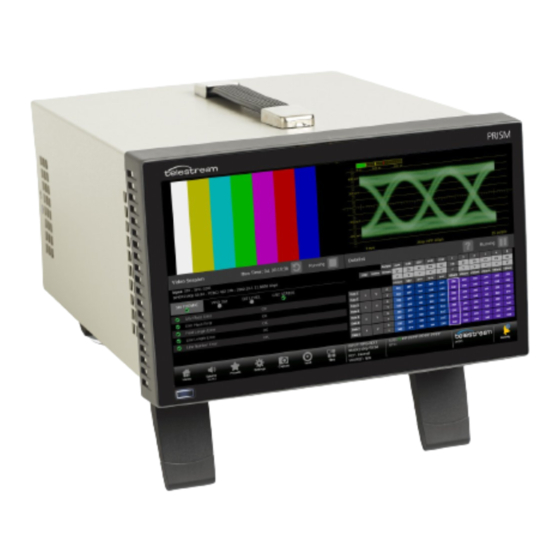
PRISM Model Form Factors The PRISM SDI / IP Waveform Monitor is available in two form factors: The PRISM MPI is 3RU half-rack width with integrated 9-inch HD display and touch panel. Option PHY is available to add physical layer measurement sets. - Page 24 Level A, Two Sample Interleave Quad Link 3G-SDI 3840x2160 4:2:2 YCbCr 50/59.94/60p MP2-FMT-4K Level B, Two Sample Interleave 6G-SDI 3840x2160 4:2:2 YCbCr 23.98/24/25/29.97/ MP2-FMT-4K 12G-SDI 3840x2160 4:2:2 YCbCr 50/59.94/60p MP2-FMT-4K Quad Link 12G-SDI 7680x4320 4:2:2 YCbCr 50/59.94/60p MP2-FMT-8K PRISM MPI-MPX User Manual...
- Page 25 Reception of 48-kHz streams with 1 to 8 channels at packet times of 1 ms or 1 to 8 channels at packet times of 125 µs µs. 1. Also supports reception of 48 kHz with 1 to 6 channels at packet times of 125 PRISM MPI-MPX User Manual...
- Page 26 Stop, False Color, Light meter, HDR/WCG Conversion, CIE, and HDR Measurements. • MP2-GEN adds a node-locked license for SDI/IP signal generator; this includes IP/ SDI Generator application. • MP2-EXTNDSP adds a node-locked license for enabling extended desktop. PRISM MPI-MPX User Manual...
-
Page 27: Rack Mounting
MPI Monitor There are two optional dual rack cabinets (19-inch, 3RU) available for the PRISM monitor. Each of the cabinet kits include the PRISM MPI Dual Rack Cabinet and Extender Installation Instructions document (part number 071-3725-xx). MPI-RACK-MM Allows you to install one MPI unit or two MPI units side-by-side. Each side of the cabinet front panel has two USB ports and a headphone port for each MPI unit. - Page 28 MPX2. A software license is required to enable the extended display feature. For information on how to install and use this extended display, see the PRISM MPX2-DUALDSP Installation and Safety Instructions. PRISM MPI-MPX User Manual...
- Page 29 Caution: To minimize the risk of damage to the instrument, we strongly recommend the power cord be connected to the instrument before the power cord is connected to the AC power source. PRISM MPI-MPX User Manual...
- Page 30 Note: If the PRISM monitor was previously powered off by a power interruption or by removing the power cord from the rear of the instrument, the instrument powers on when power is reapplied. 2. Press the power button on the instrument front panel to turn the instrument on. PRISM MPI-MPX User Manual...
-
Page 31: Mpi Power-On And Power-Off Procedures
Settings, Utilities, Power, and then Power Down Now. 2. To completely remove power from the instrument, disconnect the power cord from the AC power source and then disconnect the power cord from the instrument. MPI Power Cord Removal.) (See PRISM MPI-MPX User Manual... -
Page 32: Mpx Power-On And Power-Off Procedures
Caution: To minimize the risk of damage to the instrument, it is strongly recommended that the power cord be connected to the instrument before the power cord is connected to the AC power source. PRISM MPI-MPX User Manual... - Page 33 Settings, Utilities, Power, and then Power Down Now. 2. To completely remove power from the instrument, disconnect the power cord from the AC power source and then disconnect the power cord from the instrument. MPI Power Cord Removal.) (See PRISM MPI-MPX User Manual...
-
Page 34: Sfp Module Installation
SFP module in an anti-static bag or container. Caution: To prevent possible damage to the PRISM monitor and SFP modules, remove the SFP modules before transporting the PRISM monitor. PRISM MPI-MPX User Manual... -
Page 35: Network Installation
(DHCP) or manually. If your network does not use DHCP, you must manually enter the address for the instrument. To get a fixed address, talk to your LAN administrator. The default IP address of the PRISM monitor is 192.168.1.2. PRISM MPI-MPX User Manual... - Page 36 This may cause a non-deterministic operation, such as IGMP leaves failing or other network connectivity issues. 7. Select the Settings icon ( ) or select the Close icon ( ) to close the Settings menu. PRISM MPI-MPX User Manual...
- Page 37 MPI Rear Panel Connectors MPI Rear Panel Connectors The illustration shows the external connections on the rear panel of the MPI instrument. A description of each connector is provided. Descriptions of numbered PRISM MPI rear-panel connectors Item Connector label, number...
- Page 38 Getting Started MPI Rear Panel Connectors Descriptions of numbered PRISM MPI rear-panel connectors Item Connector label, number symbol, or end Description SDI SFP+ Two optional SFP outputs are for SDI signals (HD-BNC transmitter SFP+ modules shown). SDI SFP outputs 1 and 2 supports HD/3G signals.
-
Page 39: Mpi Rear Panel Connectors
Getting Started MPI Rear Panel Connectors Descriptions of numbered PRISM MPI rear-panel connectors Item Connector label, number symbol, or end Description SERIAL Serial interface, 9-pin connector, is not used. Ethernet port is a standard RJ-45 connector for 10/100/1000Base- T Ethernet cable. - Page 40 Quadlink inputs (4k/8k) the Aux out is link 1 ST2110-20/30 inputs are supported. 10GbE Two optional SFP ports for 10 GbE Ethernet applications. SFP+ 2-1 Two optional SFP outputs for SDI signals. SDI SFP inputs 3 and 4 support HD/3G signals. SFP+ 4-3 PRISM MPI-MPX User Manual...
- Page 41 REF OUT is a pass through of the REF IN. Audio input port is for future use. Audio output (1/8-inch—3.5mm—line out) port is for headphones to listen to the selected audio channel pair. Microphone input port is for future use. PRISM MPI-MPX User Manual...
-
Page 42: Mpx Rear Panel Connectors
2. 2 Audio output is an 1/8-inch (3.5mm) diameter port for a headset. It has connections for L and R audio channels. Headset plugs that are an 1/8-inch and have an additional contact for a microphone may not work because the headphone ports are not set for the spacing requirements of a third connection on the plug. PRISM MPI-MPX User Manual... - Page 43 Descriptions of PRISM Display Elements table. Descriptions of numbered PRISM MPI2-10 Display Elements Item number Description Applications Some applications have selectable tabs (highlighted readouts) you tabs bar can use to display additional information. Application tiles Location of the application tile PRISM MPI-MPX User Manual...
- Page 44 A number above the Activity icon indicates the number of messages waiting in and devices connected to the instrument. 1. Select the Activity icon to view the DASHBOARD messages, which includes devices connected to the instrument. PRISM MPI-MPX User Manual...
-
Page 45: Display Elements
To configure which alarms you receive notifications for, see Alarm in the Settings menu. The Activity icon is color coded: • A gray icon means no alarms have been activated. • A yellow icon means at least one alarm is active, but it is not longer present. PRISM MPI-MPX User Manual... - Page 46 – A red button means at least one alarm in the group has been activated and it is still active. Note: A red (still active) alarm takes precedence over yellow. If there are both active and cleared alarms in the group, the button is red. PRISM MPI-MPX User Manual...
- Page 47 – To turn on a group or groups of alarms in the DASHBOARD, select the checkbox of any alarm group. – To turn on any specific alarm or alarms, select the title of a group of alarms to see the individual alarms and select the checkbox of any specific alarm. PRISM MPI-MPX User Manual...
- Page 48 Acknowledge Alarm Notifications The notification of alarms can be acknowledged (set the alarms to green) through two methods in the Activity DASHBOARD: PRISM MPI-MPX User Manual...
- Page 49 The Event Log application displays in tile 1. • The errors are filtered by the group currently selected Dashboard Alarm Group. Filter Event Log Alarms by Group Select an alarm group and select View in tile 1. PRISM MPI-MPX User Manual...
- Page 50 Getting Started Display Elements PRISM MPI-MPX User Manual...
- Page 51 Getting Started Display Elements PRISM MPI-MPX User Manual...
-
Page 52: Methods Of Operation
This section describes the primary methods of operating the instrument: • MPI front panel touchscreen • MPX front panel controls • External touchscreen display • Keyboard and mouse • Remote control using VNC • Remote control using API commands PRISM MPI-MPX User Manual... -
Page 53: Touchscreen Operation
Some applications support pinch and zoom. Note: The terms “tap”, “swipe”, and “pinch” apply to the touchscreen on the instrument. If you are using a mouse and keyboard you must “click”, “scroll” and use the scroll wheel on the mouse. PRISM MPI-MPX User Manual... - Page 54 3. Select the touch indicator size from the options: Dot, Small, Med, or Large. The Touch Indicator Example shows what the indicator will look like. Turn off the Touch Indicator, in the Touch Settings menu, in the Touch Indicator Size options, select Off. PRISM MPI-MPX User Manual...
-
Page 55: Select And Organize Applications
– Select an application marked with a number to remove it from the application toolbar. Note: Removed applications leave that space open in the Application toolbar only while the menu is in edit mode. If there is a space in the application list when the PRISM MPI-MPX User Manual... - Page 56 1. Select the Tiles icon ( ) and then select the All Application menu icon ( 2. In the All Applications menu header, select the Colored Icons button to change the icon colors on or off. PRISM MPI-MPX User Manual...
- Page 57 Half-screen Tiles There are several half-screen configurations. Select the Tiles icon ( ) and then select the half-screen icon ( ) to enlarge the tile vertically and the reduce icon ( ) to return to quarter screen. PRISM MPI-MPX User Manual...
- Page 58 Double tap on the application to change it between full-screen and quarter- or half-screen mode. • Select the Tiles icon ( ) to open the application toolbar and select the quarter- screen icon ( ) or the full-screen icon ( ) to change between views. PRISM MPI-MPX User Manual...
- Page 59 ) to change between modes. Extend Tile Vertically (Half-screen Mode) • In the application toolbar, select the expand icon ( ) to expand the tile vertically; • Select the compress icon ( ) to collapse the tile to a quarter-screen. PRISM MPI-MPX User Manual...
-
Page 60: On-Screen Tools
Position. For instructions on how to use each on-screen tool, see these application sections: • Waveform Application On-screen Tools • Vector Application On-screen Tools • Stop Display Application On-screen Tools • Lightning Application On-screen Tools PRISM MPI-MPX User Manual... -
Page 61: Keyboard And Mouse Operation
Selects Input 1 or selects Preset 1 from the selected preset group. Select 2 Selects Input 2 or selects Preset 2 from the selected preset group. Select 3 Selects Input 3 or selects Preset 3 from the selected preset group. PRISM MPI-MPX User Manual... - Page 62 ALT and at the same time and press p three times to make a selection from Preset Group C. 2. Press a number from 1 to 6 to select the input or to select a preset from the selected Preset Group (A-F). PRISM MPI-MPX User Manual...
-
Page 63: Mpx Front-Panel Controls
USB ports: There are two USB 3.0 ports for connecting a mouse and keyboard, importing or exporting instrument presets, upgrading the instrument firmware, or saving screen and stream captures. PRISM MPI-MPX User Manual... - Page 64 To select an input to monitor using the front panel: 1. Press the INPUT button to prepare the instrument for an input selection. 2. Press the SELECTIONS numbered button corresponding to the input you want to monitor. PRISM MPI-MPX User Manual...
-
Page 65: Remote Control Through Vnc Operation
3. Enter the new hostname.in the Hostname field. Connect through Web Browser 1. On the PRISM monitor to connect to, select the Settings icon ( ), then select Network, and find the Control IP Port IP address of the instrument. PRISM MPI-MPX User Manual... - Page 66 3. Enter the hostname or IP address in a web browser. The PRISM HOME page displays. 4. Select noVNC Access. A login web page displays similar to the example. 5. In the Control bar, select the Settings icon ( ) to open the Settings menu. PRISM MPI-MPX User Manual...
- Page 67 6. In the Scaling Mode list, select Local Scaling, and then select Apply. 7. In the Control bar, select the Connect icon ( ) to open the Connect menu. 8. In the Settings menu, enter the password for the PRISM, and then select Connect. PRISM MPI-MPX User Manual...
- Page 68 Note: If the tiles do not appear correctly (too large for the monitor) disconnect from the instrument, select the Settings icon ( ), and set Scaling Mode to Local Scaling, and then reconnect to the instrument. PRISM MPI-MPX User Manual...
-
Page 69: Remote Control Through Api Commands
Access the API Documentation 1. Find the PRISM hostname: on the Status bar, under the Telestream logo, next to the Activity icon. Or find the IP address: select Settings, then Network, and under CONTROL IP PORT find the IP Address. - Page 70 Methods of Operation Remote Control through API Commands PRISM MPI-MPX User Manual...
-
Page 71: Configure The Instrument
Verify Firmware Upgrade Installed software and hardware versions: Note: Some of the configuration settings require you to enter values. A USB keyboard can be used to enter these values instead of using the touchscreen keypad on the instrument. PRISM MPI-MPX User Manual... -
Page 72: Configure And Select Signal Inputs
1. Select the Settings icon ( ) to open the Settings menu. 2. Select Inputs to open the inputs submenu. 3. Select an input and then select SDI. Note: The virtual inputs can be given any meaningful name. PRISM MPI-MPX User Manual... - Page 73 Quad Link C is connected to SDI-IN 3 Quad Link D is connected to SDI-IN 4 Note: All four SDI inputs must be connected to a cable on the back of the PRISM to use Quad Link Inputs. PRISM MPI-MPX User Manual...
- Page 74 Color Gamut settings define the characteristics of the video signal. Note: The preferred setting for all video options is Auto. At this setting the PRISM determines the correct settings from the signal or any metadata (if present). PRISM MPI-MPX User Manual...
- Page 75 3. If a 3-gigabit transport is being used, select the In 3G-SDI drop-down menu and choose: – Auto: The system selects the correct setting based on the information in the incoming signal. – Level A – Level B PRISM MPI-MPX User Manual...
- Page 76 S-Log3 (Live HDR): The reference OETF and OOTF (Optical to Optical Transfer Function) is defined as Sony S-Log3 (Live HDR). – Log C: The reference OETF is defined as ARRI Log C. Note: The Structure menu is set to Auto., which is YCbCr 4:2:2 10bit. PRISM MPI-MPX User Manual...
- Page 77 2. Choose the type of audio. Select PCM Select DOLBY (use of Dolby requires the MP2-DLBY license). Select PCM a. Under AUDIO, select PCM. b. Select Program Configuration. The Prgm Cfg menu opens. c. Set the Program Configuration slider to On. PRISM MPI-MPX User Manual...
- Page 78 Default resets the channels to 8 stereo pairs. Clear removes all assignments, including the default. f. Select Save and close the menu. Note: You must save the program configuration to update the programs in the audio bars and loudness meter. PRISM MPI-MPX User Manual...
- Page 79 In the Dolby Audio Channel Pair menu, select the audio channel pair that contains Dolby audio. Identify the Dolby audio channels: Open the Audio application. ii. Return to the Input menu and select the PCM option in Audio. PRISM MPI-MPX User Manual...
- Page 80 The audio programs in the Dolby stream are automatically set up based on the Dolby metadata. Rename Virtual Input 1. Select the Settings icon ( ) to open the Settings menu. 2. Select Inputs to open the Inputs submenu. PRISM MPI-MPX User Manual...
- Page 81 6. When you are done editing the input, select Save to save your changes. Configure IP Inputs Set ST 2022-6 Configuration 1. Select the Settings icon ( ) to open the Settings menu. 2. Select Inputs to open the Inputs submenu. 3. Select the input from the list. PRISM MPI-MPX User Manual...
- Page 82 Note: Path 2 is only available if ST2022-7 Seamless Switching is enabled. You may have to scroll down to see Path 2. 8. To have the instrument ignore a parameter, select the Unmasked control next to the parameter to change the state to Masked. PRISM MPI-MPX User Manual...
- Page 83 ST2110 menu has a different layout. The settings define the characteristics of the video signal. 1. Select Video. 2. Select the Gamma Curve menu and choose the setting. The selection characterizes the video signal on each virtual input. PRISM MPI-MPX User Manual...
- Page 84 The selection is the color space of the video signal. a. Rec. 709: Standard for HD. b. Rec. 2020: Standard for 4K. Note: Rec. 709 gamut is automatically selected when the SD format is detected or selected in the video signal. PRISM MPI-MPX User Manual...
- Page 85 MP2-DLBY license). Select PCM: a. Under AUDIO, select PCM. b. Select Program Configuration. c. Set the Program Configuration control to On. d. Select Edit. The Edit button disappears and the Default, Clear, and Undo buttons replace it. PRISM MPI-MPX User Manual...
- Page 86 Note: You must save the program configuration to update the programs in the audio bars and loudness meter. Select DOLBY: a. Select DOLBY. b. In the Dolby Audio Ch Pair menu, select the audio channel pair that contains Dolby audio. PRISM MPI-MPX User Manual...
- Page 87 4. Select IP and then select ST2110. 5. Set the NMOS control to Enabled or Disabled as needed. Enabling NMOS allows system management software to discover, register, configure the input, and select the active input for monitoring. PRISM MPI-MPX User Manual...
- Page 88 Note: Incoming 10-bit ST 2110-20 data is supported in the range 4-1019. Incoming data less than the minimum is reduced to 4 and data above the maximum is reduced to 1019. 1. Under ST2110, select the Video tab. 2. Set the Enable Video control to Enabled. PRISM MPI-MPX User Manual...
- Page 89 Configure Audio (2110-30) Stream Note: To decode Audio (2110-30) stream, it’s necessary for Video (2110-20) to be available and subscribed. 1. Under ST2110, select the Audio (2110-30) tab. 2. Set the Enable Audio control to Enabled. PRISM MPI-MPX User Manual...
- Page 90 Note: The Bit Depth is already set to 24. 7. Set Program Configuration: a. Select Program Configuration. The Prgm Cfg menu opens. b. Set the Program Configuration control to On. PRISM MPI-MPX User Manual...
- Page 91 Note: You must save the program configuration to update the programs in the audio bars and loudness meter. Note: If the number of audio channels present does not complete a group (4 channels) the remaining channels in the group will be labeled “Z BIT”. PRISM MPI-MPX User Manual...
- Page 92 Monitor general purpose RTP streams: 1. Select the Settings icon ( ) to open the Settings menu. 2. Select Inputs to open the Inputs submenu. 3. Select the input from the list. PRISM MPI-MPX User Manual...
- Page 93 ) from the Status bar at the bottom of the PRISM monitor. 2. Select a configured input from the list in the bottom bar. 3. Select the Home icon ( ) to close the Input selection controls. PRISM MPI-MPX User Manual...
-
Page 94: Configure Instrument For Hdr/Wcg Monitoring
BT. 709 Gamma / Gamut displays. The conversion between input video and linear light is processed in Scene light. Note: Convert to Rec. 709 mode is not supported for SD signals. PRISM MPI-MPX User Manual... -
Page 95: Enable Nmos
4. Close the Network menu. Note: When changes are made to the control port IP address or the label of the instrument and NMOS is being used for configuration, we recommend rebooting the instrument to update the NMOS registration server. PRISM MPI-MPX User Manual... -
Page 96: Adjust Audio Settings
Note: The view varies based on the visibility selection of other auxiliary audio displays including Audio Session or Lissajous Display. Configure Loudness Display 1. Select the Settings icon ( ) from the status bar. 2. Select Audio to open the Audio submenu. PRISM MPI-MPX User Manual... - Page 97 Loudness display with appropriate color code) LOUDNESS Loud is 0 to -30 and Sets the limits to trigger in-bar status for THRESHOLDS quiet and loud level Quiet 0 to -60 Full Scale Loudness PRISM MPI-MPX User Manual...
- Page 98 Loudness meter measures the levels based on that audio program. Note: Changing the selected Audio program that the Loudness meter measures changes the headphones or speaker pair, and changing the headphones or speaker PRISM MPI-MPX User Manual...
- Page 99 The green letters in the status bar (marked as 3) mark the channels the Loudness display is measuring and where they are in the channel series. Meter Controls • To start and stop the loudness meter: select the play ( ) or stop ( ) button. PRISM MPI-MPX User Manual...
- Page 100 • Mono: Reduces the stream to one channel. The center channel is reduced 3dB, the surround channels are each reduced 3dB, and the LFE is muted. All 6 channels are combined. PRISM MPI-MPX User Manual...
- Page 101 Line and RF are modes of Dynamic Range Control (DRC)—compression—factors that are applied when decoding Dolby content for monitoring or output. Select Downmix Dynamic Rng. Select Line or RF. These DRC compression factors are applied when downmixing to the various Dolby D listening modes. PRISM MPI-MPX User Manual...
-
Page 102: Configure Instrument Outputs
SDI OUTPUT loop-through of IP inputs is available for SDI, ST2022-6, and ST2110-20/30 Configure Audio (2110-30) Stream (see for audio configuration details) including embedded audio streams. See the SDI Generator applications for instructions on how to configure the SDI Generator signal. PRISM MPI-MPX User Manual... -
Page 103: Configure To Decode Timecode
2. Select Anc Data to open the Anc Data submenu. 3. In Timecode Format select LTC or VITC as needed and close the menu. The selected timecode appears in the bottom border of the Status frame and all alarms and events. PRISM MPI-MPX User Manual... -
Page 104: Configure Reference Settings
10-GE SFP Port 1 input on the back panel. Note: When a reference selection is made the reference changes in the status bar and in the Timing application. Configure Analog Reference Settings 1. Select the Settings icon ( ) to open the Settings menu. PRISM MPI-MPX User Manual... - Page 105 2. Select Reference to open the Reference submenu and select the PTP Settings submenu. 3. To enable or disable PTP logging to the Event Log, select the control box to change the setting to the state. PRISM MPI-MPX User Manual...
- Page 106 ) to remove the existing domain number. – Select the backspace key to delete characters by backspacing over them. 8. When you are done editing the domain number, select the Enter key. 9. Repeat steps 4 to 8 for each PTP profile. PRISM MPI-MPX User Manual...
-
Page 107: Set And Recall Instrument Presets
(Recall). You can assign any preset button with any configuration of applications, outputs, and inputs. When edit mode is off, selecting a preset button only recalls the preset settings assigned to that button, with no confirmation. PRISM MPI-MPX User Manual... - Page 108 There are 6 presets in each of 6 groups. Use the arrow buttons ( ) or swipe left or right to move to the preset group (A–F). Note: When a preset has no content, <empty> is displayed on the preset button. PRISM MPI-MPX User Manual...
- Page 109 If Rename does not appear, Edit mode is not on. 4. Select Save. Rename Group of Presets 1. Select the Settings icon ( ) to open the Settings menu. 2. Select Presets to open the Presets submenu. PRISM MPI-MPX User Manual...
- Page 110 (this includes naming an <empty> preset). 5. Select the name box of the preset you want to name or rename. An on-screen keyboard displays. Note: You can also rename a preset group by selecting a group name box. PRISM MPI-MPX User Manual...
- Page 111 ) and then select the Eject icon ( ) to unmount the USB drive from the instrument. 7. Remove the USB drive with the presets from the PRISM. 8. To upload the presets to another PRISM, go to Upload Presets from USB Drive. PRISM MPI-MPX User Manual...
- Page 112 9. Repeat steps 1 to 9 for any other PRISMs to copy the presets. Download File of Presets Locally 1. Use a web browser to access the PRISM HOME page for the PRISM with the presets. PRISM MPI-MPX User Manual...
- Page 113 1. With the presets file downloaded locally, go to the PRISM HOME page for the PRISM to upload the presets. 2. Select Preset Download and Upload. 3. Select Upload to PRISM and then select Browse. A file explorer window displays. PRISM MPI-MPX User Manual...
- Page 114 Note: The preset still has all of the input settings, they are just not applied when the Recalled Saved Inputs setting is off. 1. Select the Settings icon ( ) to open the Settings menu. 2. Select Presets to open the Presets submenu. PRISM MPI-MPX User Manual...
- Page 115 The next table lists some of the settings that are reset. Note: Custom presets are still available after recalling the factory preset. Instrument settings reset by Recall Factory Preset Item Setting Tile 1 application Waveform Tile 2 application Video Session Tile 3 application Picture PRISM MPI-MPX User Manual...
- Page 116 SDI-In 4 Input type Input connector SDI 4 SDI-SFP 1 input configuration Input name SDI-SFP 1 Input type Input connector None selected SDI-SFP 2 input configuration Input name SDI-SFP 2 Input type Input connector None selected PRISM MPI-MPX User Manual...
- Page 117 PTP reference configuration PTP Logging to the Event Log Enabled Selected Profile ST2059 ST2059 domain ST2059 communication mode Multicast SDI Generator configuration Enable SDI Generator Disabled IP Generator configuration Enable IP ST2110 Generator Disabled Reference Internal PRISM MPI-MPX User Manual...
-
Page 118: Set Syslog Setup
4. Fill in Syslog Server Port with the number configured in the syslog server software. Note: For questions on configuring your syslog server software, contact your system administrator. 5. Select Save. The syslog server software collects events and alarms, and displays the details. PRISM MPI-MPX User Manual... -
Page 119: Snmp Functionality
– GET and POST are allowed commands. – In these examples, replace "aaa.aaa.aaa.aaa" with the IP address of the PRISM the sending the traps and "bbb.bbb.bbb.bbb" with the IP address of the computer receiving the traps. PRISM MPI-MPX User Manual... - Page 120 Execute as a POST operation. 4. Set the SNMP community string: a. Enter the address of the unit aaa.aaa.aaa.aaa/api/snmp_trap_community. b. In the body of the JSON command, enter: "string" "new_trap_community" c. Execute as a POST operation. PRISM MPI-MPX User Manual...
- Page 121 From the SNMP manager, configure the SNMP agent (PRISM) IP address. b. Load the prism.mib file. c. Open the trap receiver window. d. Confirm the traps are received on the trap receiver window of the MIB browser application on the destination machine (on port 162). PRISM MPI-MPX User Manual...
-
Page 122: Configure Alarms
Threshold for the group. Select Specific Alarm 1. Select the Settings icon ( ), select Alarms, and then select the alarm group that contains the specific alarm. 2. Select the UI checkbox of the alarm to monitor. PRISM MPI-MPX User Manual... - Page 123 The example alarm is set for 1 second duration of -30%. The percentage describes the location on the correlation meter (below the lissajous image) in the Audio application. So long as the phase marker (green diamond) does not PRISM MPI-MPX User Manual...
- Page 124 Duration and the Min percentage of the audio pair phase can be set. Audio Signal Lost: No Audio is present in the currently active signal. PRISM MPI-MPX User Manual...
- Page 125 UI responds, but no alarms are generated and none are logged. Note: When Gamut is disabled, no Gamut alarms are generated or logged. Note: The Gamut Preset button, EBU R103, only resets the YRGB numbers, not the Picture Area or Frame Duration. PRISM MPI-MPX User Manual...
- Page 126 Timing Drift: Input signal is not frequency locked to the reference signal. Drift rate is more than 10 µs of timing change on a 20-second window, larger drift rates are detected faster. Video and Reference Mismatch: Detected format of the external reference signal is not com- patible with the input signal format. PRISM MPI-MPX User Manual...
- Page 127 An error means that the Y Channel embedded CRC value does not match the calculated CRC value, which indicates that a transmission error has occurred. SMPTE 352M Payload ID Missing: A mandatory ST 352M video payload identifier packet is missing. PRISM MPI-MPX User Manual...
- Page 128 Format setting (which is set to a specific line rate, rather than being set to Auto) in the SDI Input submenu of the Configure menu or the setting specified in the ST 352 payload (if present). Video Signal Lost: Video input signal has not been detected at the selected input. PRISM MPI-MPX User Manual...
-
Page 129: Set Trace And Graticule Intensity
) to increase intensity or the minus icon ( ) to decrease intensity of the trace or graticules. Note: The intensity can also be adjusted by selecting anywhere in the slider or selecting and dragging the slider circle left or right. PRISM MPI-MPX User Manual... -
Page 130: Set Time And Date
2. Select the Time Zone menu to select the correct time zone offset for your location. The selection names include the time offset from UTC and major cities in those time zones. 3. Select Save to update the clock. A reboot is not required to change the time zone. PRISM MPI-MPX User Manual... - Page 131 2. Adjust the time and date using the up and down arrows as needed. The time setting uses a 24-hour clock, so no AM/PM setting is required. 3. When you are done setting the time and date, select Save. PRISM MPI-MPX User Manual...
- Page 132 4. The message box asks you to confirm you want to reboot the instrument to implement the time and date changes: – Select OK to reboot the instrument immediately and implement the changes. – Select Cancel to end the operation. PRISM MPI-MPX User Manual...
-
Page 133: Upgrade Instrument Firmware
Configure the Instrument Upgrade Instrument Firmware Upgrade Instrument Firmware Telestream releases updates to product firmware to add new features or to fix reported problems. Check the Telestream website regularly for new firmware releases. Before You Begin You do not need to perform a firmware upgrade if the instrument has the latest version of firmware already installed. - Page 134 Caution: Removing the USB drive or powering off the instrument before the upgrade is complete can cause upgrade failure. To prevent upgrade failure, wait until the Installation Complete message box is displayed before performing these actions. Note: The upgrade may take up to five minutes. PRISM MPI-MPX User Manual...
- Page 135 1. Select the Settings icon ( ) to open the Settings menu. 2. Select Utilities and then select Version. 3. Verify the displayed firmware version number matches the version of the firmware upgrade package you installed. PRISM MPI-MPX User Manual...
-
Page 136: Upgrade Software License
For further assistance, contact our technical support team: www.telestream.net/telestream-support/video/support.htm. Verify Software License Upgrade 1. Select the Settings icon ( ) to open the Settings menu. 2. Select Utilities and then select Options. 3. Verify that the displayed option(s) match the options you installed. PRISM MPI-MPX User Manual... -
Page 137: Troubleshooting
Troubleshooting If the instrument needs service, you may be asked to provide the diagnostics file to Telestream to aid in understanding any problems with the instrument. To download a zip file containing a service report of instrument diagnostics: 1. Select the Settings icon ( ) to open the Settings menu. -
Page 138: Functions
Functions Functions This section describes additional functions available on the PRISM monitor. • Headphone and speaker volume, balance, and source adjustment • Stream Capture PRISM MPI-MPX User Manual... -
Page 139: Headphone Or Speaker Volume, Balance, Device, And Source Adjustment
3. Select the input with the channels to downmix. a. If the input is SDI, select AUDIO. b. If the input is 2022, select AUDIO. 4. Check the Program Configuration is on and configured for the input. 5. Select Save. PRISM MPI-MPX User Manual... - Page 140 Mono: Reduces the stream to one channel. The center channel is reduced 3dB, the surround channels are each reduced 3dB, and the LFE is muted. All 6 channels are combined. PRISM MPI-MPX User Manual...
- Page 141 (visible when only Program Configuration is on and set) Audio Audio channels available to monitor sources WARNING: To avoid damaging your hearing, always turn the volume down to the minimum before you put on headphones and then turn the volume up slowly. PRISM MPI-MPX User Manual...
-
Page 142: Capture
1. From the Settings menu, select Capture. Note: If the Capture configuration menu does not appear under the Settings menu, option MP2-IP-MEAS is not installed, but screen captures are still functional. 2. Select Screenshot under SELECT CAPTURE TYPE. PRISM MPI-MPX User Manual... - Page 143 3. On the application bar select the Capture icon ( A screenshot is saved to the device. Note: The screenshot API is for Telestream internal use only. If you need to remotely save a screenshot to a flash drive, use VNC.
- Page 144 A screenshot and pcap file are saved to the attached USB device. The name of the file and the path to the file on the USB device are displayed after the save is complete. 8. Select OK to close the menu. PRISM MPI-MPX User Manual...
-
Page 145: Application Information
To see the All Application menu, select the Tiles icon ( ) and then select the All Application menu icon ( Note: Some displays require a specific option to be installed. For example, the IP Graph display is not accessible unless you have Option MP2-IP-MEAS. PRISM MPI-MPX User Manual... -
Page 146: Application Options
Application: Use this application to view the picture decoded from the incoming video signal. Video Session Application: Use this application to view information about the format of the signal and metrics for SDI Format, VPID SMPTE ST352, Bit Level, and CRC Status. PRISM MPI-MPX User Manual... - Page 147 PIT, RTP sequence errors, video CRC errors, and TS-DF (Time Stamped Delay Factor). PIT Histogram Application: Use this application to view a histogram of the PIT (Packet Interval Time) to monitor network delay variation statistics. PRISM MPI-MPX User Manual...
-
Page 148: Option Mp2-Gen
Application: Use this application to provide an IP test signal to check the receiver device and signal path. SDI Generator Application: Use this application to provide an SDI test signal to check the receiver device and signal path. PRISM MPI-MPX User Manual... -
Page 149: Options Mp2-Eng And Mp2-Qc
Use this application to display the wave shape of the jitter and allows you to view additional time- domain information. Eye Application Use this application to view an eye pattern diagram of the SDI input only. PRISM MPI-MPX User Manual... -
Page 150: Option Mp2-Prod
This additional application is available when Option MP2-DLBY or MP2-AUD is installed: Application icons Description Audio Application: This option adds Lissajou, Session, Correlation, and Loudness capabilities to the existing Audio application. Dolby Status Application: Use this application to show metadata content in the selected Dolby audio stream. PRISM MPI-MPX User Manual... - Page 151 Indicates the signal parameter was in an error condition but the error has now cleared. Indicates the signal parameter is currently in an error condition. Indicates the signal parameter is not being monitored for an error condition. PRISM MPI-MPX User Manual...
-
Page 152: Waveform Application
The Waveform display is a signal-level versus time display of the video signal. Waveform Settings Menu Open the Waveform Settings menu: 1. Select the Tiles icon ( 2. Select the tile with the Waveform application. 3. Select the Tile icon ( PRISM MPI-MPX User Manual... - Page 153 Select the menu to select from these choices (only available while displaying SDI inputs) in the menu: • Y: Displays the input as Luma (Y) components. • RGB: Displays the input as Red (R), Green (G), and Blue (B) components. PRISM MPI-MPX User Manual...
- Page 154 • The nits graticule varies depending on the Gamma selection in Input Settings menu. This is the Display light graticule and is used for mastering the content for a targeted HDR system. PRISM MPI-MPX User Manual...
- Page 155 Waveform settings menu, through on-screen tools. Select the tool/button for the setting you want to adjust. All the available tools are located on the top and bottom of the display and are highlighted PRISM MPI-MPX User Manual...
- Page 156 Gain Increase or decrease the magnification of the trace display. 1. Select the Gain button to expand the available magnification options drop down list. 2. Select one of the preset magnifications for fixed gain. PRISM MPI-MPX User Manual...
- Page 157 For fine increments, select the plus or minus buttons to adjust the gain. • The scroll wheel on a mouse adjusts the variable gain. • Select the Reset icon ( ) to remove variable gain adjustments. Horizontal and Vertical Position Adjust the position of the trace display. PRISM MPI-MPX User Manual...
- Page 158 – Use a mouse scroll wheel to move the trace. – For small adjustments, use the plus or minus button to adjust the vertical position. – Use the Reset icon ( ) to reset the vertical position adjustment to default. PRISM MPI-MPX User Manual...
- Page 159 Select and hold anywhere on the cursors to move them and mark exact times in the trace. The cursors are highlighted in yellow when moved. The time stamp of each cursor and the delta are displayed on the right side of the application. PRISM MPI-MPX User Manual...
- Page 160 Display Mode Change how the waveforms are displayed. • Select the button in the bottom left corner of the application to expand the available display options (the button label varies depending on the last option selected). PRISM MPI-MPX User Manual...
- Page 161 Select the button in the bottom right corner of the application to expand the available display format options. • Select the Mag option to set the magnification to Best, 1.0x, 10.0x, 20.0x, or 25.0x. • Select the Display Style option to switch between Parade or Overlay. PRISM MPI-MPX User Manual...
- Page 162 Note: The same line is selected in any trace display if line select is enabled. To turn on Line Select (and choose the line to monitor): 1. Select the Lines button at the bottom of the tile. PRISM MPI-MPX User Manual...
- Page 163 Note: In link, the letters (A, B, C, or D) refers to the physical links. The numbers (1, 2, 3, or 4) refers to the virtual links. For example, A3/62 indicates it is physical link 1 and virtual link 3 (in a 2-sample interleave, 12G transport). PRISM MPI-MPX User Manual...
-
Page 164: Vector Application
2. Select the tile with the Vector application. 3. Select the Tile icon ( Note: The Move icon ( ) is in the settings menu header. Select this icon to move the settings left of right. PRISM MPI-MPX User Manual... - Page 165 If 1 Line is selected then the display only shows results for the selected line in the picture. The line can be selected using the on-screen tools; see Line Select Function. Or the line can be selected directly on the Picture. PRISM MPI-MPX User Manual...
- Page 166 On a touchscreen, you can use a pinch gesture to change the scale of the trace for large increments. 3. Select VAR: (On or Off ) to turn the variable gain on or off. Variable gain (VAR: On) allows you to change the gain factor (Var Gain) in 0.01 incre- ments. PRISM MPI-MPX User Manual...
- Page 167 5.0x has a range of 1.25x to 20.00x gain. – 10.0x has a range of 2.50x to 40.00x gain. Select the Reset icon ( ) to remove variable gain adjustments and reset the gain to 1.00 and 1.0x. PRISM MPI-MPX User Manual...
- Page 168 – Use a mouse scroll wheel to move the trace. – For small adjustments, use the plus or minus button to adjust the horizontal position. – Select the Reset icon ( ) to reset the horizontal position adjustment to default. PRISM MPI-MPX User Manual...
- Page 169 1. Select the LUT button (other elements in the button are variable depending on the options selected) in the upper middle of the display. 2. Select the lower LUT: button to set the Gamma LUT on or off. PRISM MPI-MPX User Manual...
- Page 170 Note: The same line is selected in any trace display if line select is enabled. To turn on Line Select (and choose the line to monitor): 1. Select the Lines button at the bottom of the tile. PRISM MPI-MPX User Manual...
- Page 171 Note: In link, the letters (A-D) refers to the physical links. The numbers (1-4) refers to the virtual links. For example, A3/62 indicates it is physical link 1 and virtual link 3 (in a 2-sample interleave, 12G transport). PRISM MPI-MPX User Manual...
-
Page 172: Audio Application
MP2–AUD. Dolby E decoding requires option MP2-DLBY. The 32- channel audio support requires option MP2-FMT-8K. Audio Settings Menu Open the Waveform Settings menu: 1. Select the Tiles icon ( 2. Select the tile with the Waveform application. 3. Select the Tile icon ( PRISM MPI-MPX User Manual... - Page 173 The meter bars are displayed below the Test level in green. • Between the Test level and the Peak Program level, the meter bars are displayed in yellow. • Above the Peak Program level, the meter bars are displayed in red. PRISM MPI-MPX User Manual...
- Page 174 LCR or LRC. Bar Ballistics Displays the selected ballistics for the level-meter dynamic response, above the level meter, on the left. To change the ballistics: 1. Select the Settings icon ( ) and then select Audio. PRISM MPI-MPX User Manual...
- Page 175 For uncorrelated signals, the indicator is yellow and tends to stay in the middle (around 0). • For anti-correlated signals (one goes up when the other goes down), the indicator is red and moves to the left (towards -1). PRISM MPI-MPX User Manual...
- Page 176 A1 and the next 16 channels comes from the link B1. The two Audio applications must be selected in two tiles to display the 32-channel audio bars. Lissajous Display The Lissajous display is a visual of a user-specified pairing of channel inputs with a channel correlation meter. PRISM MPI-MPX User Manual...
- Page 177 This instrument maintains a running audio loudness session. Note: The Loudness measurement is available for mono, stereo, 5.1, and multi- channel audio programs. PRISM MPI-MPX User Manual...
- Page 178 Note: The Audio tile appearance can vary based on the selection of other auxiliary audio displays, including Audio Session or Lissajous Display. Configure Loudness Display 1. Select the Settings icon ( ) to open the Settings menu. 2. Select Audio to open the Audio submenu. 3. Select Loudness Settings. PRISM MPI-MPX User Manual...
- Page 179 DC. DC Block The Emphasis Filter compensates for dispersion effects from Nyquist filters in the Emphasis Filter broadcast chain that make it difficult to measure and control the peak levels of high‐frequency signals. Dialogue Intelligence enabled PRISM MPI-MPX User Manual...
- Page 180 Note: The low-frequency effects channel (Lfe1) in 5.1 and 7.1 is not used in the loudness calculations. Loudness Meter Labels • The labels at the bottom of the audio bars (marked as 1) in this example means it is program 2 and there is a left and a right channel. PRISM MPI-MPX User Manual...
- Page 181 To start and stop the loudness meter: select the play ( ) or stop ( ) button. • To reset the measurement run time: select the reset button ( • The Audio Session and Loudness measurements can be independently stopped, started, and reset with the controls. PRISM MPI-MPX User Manual...
- Page 182 Under LOUDNESS METERING MODE select from the four options: • BS.1770-1 plus Dialogue Intelligence • BS.1770-2 plus Dialogue Intelligence • BS.1770-2 • Leq(A) plus Dialogue Intelligence Note: A-weighting—Leq(A)—biases the response toward that of human hearing. 4. Turn on the surround Dominance Indicator if needed. PRISM MPI-MPX User Manual...
- Page 183 Center volume indicator: displays the sound volume of the center channel as a vertical yellow bar between the L and R channels, and connects the ends of the L, C, and R audio level indicators with straight lines. PRISM MPI-MPX User Manual...
- Page 184 PSI, the bar continues to grow at a 45° angle for negative signal correlations. The bar to the right of the white tic mark behaves similarly, depending on the C-R correlation. This PSI indicator uses the same color coding as the other PSI indica- tors. PRISM MPI-MPX User Manual...
- Page 185 Example 2: Shows a sine wave test tone with the same level in the L,C, R, Ls, and Rs channels. All signals are in phase, creating white marks for the phantom source indicators mean that each channel has the same amplitude and frequency. PRISM MPI-MPX User Manual...
- Page 186 L and R channel at a lower level in the Ls-Rs to create a pseudo surround mix. The white marks mean a monaural channel for Ls and Rs. The other channels are uncorrelated. PRISM MPI-MPX User Manual...
- Page 187 This instrument maintains a running audio loudness session. To turn on the audio loudness values, in the Audio Settings, in Aux Display, set Loudness Meter to On. The Loudness Meter appears to the right of the Audio bars. PRISM MPI-MPX User Manual...
- Page 188 It allows you to select any one channel of a downmixed 5.1 or 7.1 stream and listen to it alone. This helps to isolate and identify an unexpected noise in a stream. To use Downmix Solo: 1. Set up a 5.1 or 7.1 stream for downmix. PRISM MPI-MPX User Manual...
- Page 189 6. Select a channel to isolate in the Audio application: – To change the solo channel, select another channel in the downmixed stream. – To return to the entire downmixed stream (without turning Downmix Solo off ), select the highlighted channel again. PRISM MPI-MPX User Manual...
-
Page 190: Picture Application
The Picture display lets you see the picture generated by the video signal. (Copyright 2008, Blender Foundation, www.bigbuckbunny.org) Picture Settings Menu Open the Picture Settings menu: 1. Select the Tiles icon ( 2. Select the tile with the Picture application. 3. Select the Tile icon ( PRISM MPI-MPX User Manual... - Page 191 Provides an overlay of the video source on the Picture application. The source data carries ANC data conforming to ST 291M. The default DID is 0x53 and SDID is 0x49. Set them as required. The source ID is limited to a maximum 15 ASCII characters. PRISM MPI-MPX User Manual...
- Page 192 When a display is selected, false color is turned on. Three false-color displays are available, which apply a color palette to the picture to highlight attributes associated False Color: Details with images. (See for more information about this feature.) PRISM MPI-MPX User Manual...
- Page 193 ARIB: This is a standard B24 of decoding. ARIB Type: Select—from HD, SD, and Mobile—the appropriate format. Note: Each Picture tile can select a closed caption format and a service. PRISM MPI-MPX User Manual...
- Page 194 1. In the Picture Settings menu, select Measurements Overlay. 2. Set Measurements Overlay to On. The Measurements Overlay appears in the Picture application. After it is visible, the overlay window can be selected and dragged to any location in the Picture tile. PRISM MPI-MPX User Manual...
- Page 195 Brightest Area (%): Defines the brightest percentage of the picture used to deter- mine the HDR threshold in nits. Darkest Area (%): Defines the darkest percentage of the picture used to determine the dark threshold in nits. PRISM MPI-MPX User Manual...
- Page 196 3. Set the Lightmeter Overlay to On. 4. Select the number of needed Lightmeter cursors (up to 5). Note: The Lightmeters all use the same method for measurements. The color of the Lightmeter cursor is just for identification. PRISM MPI-MPX User Manual...
- Page 197 To remove all the Lightmeters cursors from the Picture, unselect all of the Lightmeter colors or set the Lightmeter Overlay to Off. False Color: Details 1. Select the Picture application and then, in the applications menu, select the Tile icon ( PRISM MPI-MPX User Manual...
- Page 198 The false color ranges are defined in nits or stops depending on the gamma curve set up in the input (select the Settings icon ( ) and then select Input). If a cam- era-based gamma curve is set, such as S-Log2, the false color ranges are in stops. If PRISM MPI-MPX User Manual...
- Page 199 Enter the line number and select Enter to close. The false colors in the Picture and the Meter Overlay are updated as adjustments are made. PRISM MPI-MPX User Manual...
- Page 200 1. Select in the Picture tile, which brings up a False Color setting. 2. Select the False Color option to change between on and off. The false color shown is the most recent false color display selected in the Picture Settings menu. PRISM MPI-MPX User Manual...
-
Page 201: Video Session Application
Reset icon: Select ( ) to restart the monitoring session. Run / Stop icons: When the monitoring session is running (collecting error data), select the Stop icon ( ) to stop the session. When the monitoring session is PRISM MPI-MPX User Manual... - Page 202 Status: Shows the status of the associated error as either OK, Invalid, Missing, or Error. VPID 352 Tab Display The VPID 352 tab displays the VPID values of the SMPTE352M payload. For 3G-SDI signals, VPID is required on the primary link (Link A). PRISM MPI-MPX User Manual...
- Page 203 The CRC STATUS tab displays the status of CRC and Checksum errors in the video signal. Note: The instrument uses the RP 165 standard for error checking. For HD and 3 Gb/s signals, the CRCs change on every video line. PRISM MPI-MPX User Manual...
- Page 204 Err Secs: The number of seconds, since the last reset, that contained at least one error. % Err Fields: Shows a calculated number of the percentage of all fields since the last reset that contained at least one error. PRISM MPI-MPX User Manual...
-
Page 205: Timing Application
2. Select the tile with the Timing application. 3. Select the Tile icon ( Note: The Move icon ( ) is in the settings menu header. Select this icon to move the settings left of right. PRISM MPI-MPX User Manual... - Page 206 Compare Analog Reference with PTP 1. If not already done, choose the Setting References. See Choose External Reference. 2. In the Timing Settings Measurement Mode select Analog to PTP. The Timing application compares the Analog to PTP. PRISM MPI-MPX User Manual...
- Page 207 Horizontal: The timing difference between the reference and input signal, expressed as the line time, which remains from the total delay after the vertical offset has been removed. This has a range of ± 1/2 a line for the input format. PRISM MPI-MPX User Manual...
- Page 208 If a properly timed SDI signal is applied to a gateway, then the timing measurement on the resulting IP flow displays the combined latency in the gateway and the network. Each ST2110 stream also carries time stamps. The Stream Timing application allows for the analysis of these time stamps. PRISM MPI-MPX User Manual...
-
Page 209: Event Log Application
Undo Reset in the settings menu to show the log items that were hidden by pressing Reset. Track icon: The Track icon ( ) and the text “Tracking” to the left mean the Event Log is tracking new events. The newest events appear at the bottom of the Event Log. PRISM MPI-MPX User Manual... - Page 210 Time: Shows the time, according to the internal clock, that the error occurred in the form HH:MM:SS. Event Log Settings Menu Open the Event Log Settings menu: 1. Select the Tiles icon ( 2. Select the tile with the Event Log application. 3. Select the Tile icon ( PRISM MPI-MPX User Manual...
- Page 211 To open the group filter, select the Group heading. Note: If there is any other filter applied (Event, Date, Time—marked by a full filter icon ) next to a heading), it limits what any other filter shows. For example, if no events PRISM MPI-MPX User Manual...
- Page 212 To open the event filter, select the Event heading. Note: If there is any other filter applied (Group, Date, Time—marked by a filled filter icon— —next to a tile), it limits what any other filter shows. For example, if no PRISM MPI-MPX User Manual...
- Page 213 To select or remove the check from any single checkbox, select anywhere in the line of the title. • To scroll through the list of events, select the arrows at the top and bottom of the menu. PRISM MPI-MPX User Manual...
- Page 214 – Select in the Date From field and either enter a date (yyyy-mm-dd) with a keyboard, or select the date using the on-screen Adjust Date tool. – Repeat selecting a date in the Date To field, if needed. PRISM MPI-MPX User Manual...
- Page 215 – Select in the Time From field and either enter a time (hh-mm-ss) with a keyboard—or select the time using the on-screen Adjust Time tool—and select Enter. – Repeat selecting a time in the Time To field, if needed. Note: Other filters (duration, date) are not required. PRISM MPI-MPX User Manual...
- Page 216 – If no date, duration, or time filter is entered (no filter), the filter icon is open. – If a date, duration, or time filter is entered (a filter is applied), the filter icon is filled. PRISM MPI-MPX User Manual...
-
Page 217: Ip Status Application
2. Select the tile with the IP Status application. 3. Select the Tile icon ( Note: The Move icon ( ) is in the settings menu header. Select this icon to move the settings left of right. PRISM MPI-MPX User Manual... - Page 218 Indicates that the signal parameter was in an error condition but the error has now cleared. Indicates that the signal parameter is currently in an error condition. Indicates that the signal parameter is not being monitored for an error condition. PRISM MPI-MPX User Manual...
- Page 219 <destination IP address>:<port number>. SOURCE IP: Shows the source IP address and port number of the monitored stream in the form <source IP address>:<port number>. DEST MAC: Shows the destination MAC address of the monitored stream. PRISM MPI-MPX User Manual...
- Page 220 2022-7. Zero means no errors occurred since reset. Steady count mean errors are not occurring. Increasing count means new errors are occurring. RTP CLK: Shows the RTP clock of the monitored stream. RTP MARK: Shows the RTP marker frequency of the monitored stream. PRISM MPI-MPX User Manual...
-
Page 221: Ip Session Application
“Path”. The Port is the physical SFP port that is used to input the IP signal. Path 1 and Path 2 are the signal paths to be used for seamless switching. This differentiation is being made since it is possible for both Path 1 and Path 2 to use a single Port. PRISM MPI-MPX User Manual... - Page 222 ) to stop the session. When the session is stopped (no error data collection and no display updates), select the Play icon ( ) to restart the session. LAYER 1/2 Tab Display Select the LAYER 1/2 tab to view the status of these signal parameters. PRISM MPI-MPX User Manual...
- Page 223 64 bytes long. – Rx Oversize Packets: A count of the number of Ethernet frames received that are greater than 1522 bytes long. – Tx Bytes: A count of the number of bytes transmitted. PRISM MPI-MPX User Manual...
- Page 224 – Extension: Indicates whether an extension is present. Possible values are: • false: Indicates no extension is present. • true: Indicates an extension is present. – CSRC: Identifies the Contributing Source IDs. This value should be set to zero. PRISM MPI-MPX User Manual...
- Page 225 The signal on the SDI Out video connector may be affected. Possible interface sampling frequency declaration in stream header is incorrect for the stream type being carried. PRISM MPI-MPX User Manual...
- Page 226 • Column (0x1): Indicates column FEC is being used. • Col/Row (0x2): Indicates column and row FEC are being used. Reserved (n): When n is a number greater than 2, indicates a reserved value is being used. PRISM MPI-MPX User Manual...
- Page 227 This timestamp is fixed at the transmitter to the first information contained in the datagram. – Header Extension: Indicates the number of 4-octet Header Extension words that come after the HBRMT payload. PRISM MPI-MPX User Manual...
- Page 228 – Destination Addr: Lists the destination addresses for the L3 IP layer. • L4 UDP: – Source Port: Lists the source ports for the L4 UDP layer. – Destination Port: Lists the destination ports for the L4 UDP layer. PRISM MPI-MPX User Manual...
- Page 229 • SSRC: Identifies the Synchronization Source ID and is set in compliance with RFC3550. This identifier is chosen randomly and should be unique so no two SSRC have the same value with an RTP session. PRISM MPI-MPX User Manual...
- Page 230 The value is set to 0 for all other Media Datagrams and should be 0 for most packets. Note: For 2022-6 signals, the status indicator turns red if the Marker Bit Frequency does not match the frame rate indicated in the HBRMT header. For 2110 signals, the PRISM MPI-MPX User Manual...
- Page 231 PTP Tab Display Select the PTP tab to view the status of the PTP elements in the stream. PTP is currently only supported on 10GE SFP Port 1, for instructions on locking to PTP see Configure Reference Settings. PRISM MPI-MPX User Manual...
- Page 232 – Clock Class: This value characterizes the TAI (International Atomic Time) traceability. The clock class value varies to indicate the type of reference in use by the Grandmaster clock. For example, when locked to GPS the PTP grandmaster PRISM MPI-MPX User Manual...
- Page 233 – Peer-to-Peer: In this mode, the Pdelay request and Pdelay response messages are local to each link in the network. Each device determines the local link and device delays. The sync message from the master then collects the corrections as PRISM MPI-MPX User Manual...
- Page 234 NMOS Tab Display Select the NMOS tab to view the registration server information, server list and the last SDP file received. To enable and configure NMOS see Configure Loudness Display. PRISM MPI-MPX User Manual...
- Page 235 Last SDP File Received: Select the Last SDP File Received tab view video, audio, and data SDP files. These files contain information used to configure input signals from the registration servers. Note: Select Return to go back to the main IP Session NMOS menu. PRISM MPI-MPX User Manual...
-
Page 236: Ip Graphs Application
RTP Sequence Errors. TS-DF graph: The TS-DF graph shows the Time Stamped Delay Factor, as defined in EBU Tech 3337, which is a method for measuring network jitter in RTP streams. PRISM MPI-MPX User Manual... - Page 237 Stream type: Select this button to change to Video ( ), Audio ( ), or Data ( stream IP graphs. • Path: Select the Path button to change to Path 1, Path 2, or both Path 1 and 2. PRISM MPI-MPX User Manual...
- Page 238 Free Min: Shows the minimum available bandwidth that is not in use. Free Max: Shows the maximum available bandwidth that is not in use. Session Bit Rate Graph The Session Bit Rate graph shows the data rate of the currently selected input stream. PRISM MPI-MPX User Manual...
- Page 239 Reconstructed path errors: 0 means no sequence error have been detected and any number (not 0) means sequence error or errors detected after RTP packet reordering on each path and ST2022-7 seamless reconstruction process. PRISM MPI-MPX User Manual...
- Page 240 Path 1 minus Path 2. A positive value means that Path 2 is lagging Path Note: The measurement range of Path1-Path2 differential measurement is 1 second. Note: The Path1-Path2 differential measurement is not supported for ST 2110-30. PRISM MPI-MPX User Manual...
- Page 241 The VRX Buffer section provides a trend graph for this type of modeling. Both trend graphs help engineers properly setup the packet delivery timing in the RTP packet sender. PRISM MPI-MPX User Manual...
-
Page 242: Pit Histogram Application
Y-Axis Scaling: Select Linear or Log for the y-axis scaling. Note: The Move icon ( ) is in the settings menu header. Select this icon to move the settings left of right. Select a Y-Axis scaling option: Linear or Log. PRISM MPI-MPX User Manual... - Page 243 Std Dev: Shows the standard deviation of the packet interval time. Use the pinch and pinch-out gestures on the graph to zoom in and out. After using the zoom-in gesture, the text "Zoomed" is displayed on the x axis of the graph. PRISM MPI-MPX User Manual...
- Page 244 Note: When using a keyboard and mouse, click and drag to zoom in. Select the Reset button ( ) to set the graph back to autoscale mode. Note: The Reset button is only displayed after zooming in. PRISM MPI-MPX User Manual...
-
Page 245: Ptp Graphs Application
Elements of the PTP Graph The PTP graphs are useful in observing the effects of traffic on the PTP messages and the operation of transparent and boundary clocks. Non-PTP aware switches may have PRISM MPI-MPX User Manual... - Page 246 As the PTP is locking, the slave clock adjusts, so the trace may have large swings or jumps. As the system locks, the master-to-slave and slave-to-master delays PRISM MPI-MPX User Manual...
- Page 247 The PTP phase lag is the phase error of the phase-locked loop, which controls the slave clock. The phase lag is a reasonable estimate of how well the PTP slave is locked to the master; however, the phase lag does not indicate if there is any asymmetry in the network. PRISM MPI-MPX User Manual...
-
Page 248: Stream Timing Application
2. Select the tile with the Stream Timing application. 3. Select the Tile icon ( Note: The Move icon ( ) is in the settings menu header. Select this icon to move the settings left of right. PRISM MPI-MPX User Manual... - Page 249 Stream type tabs: Select these tabs to switch between the stream offset graphs: • VIDEO • AUDIO Note: The number in the AUDIO tab is the selected stream. • DATA Res: Lists the resolution of the graph display. PRISM MPI-MPX User Manual...
- Page 250 PTP according to the time stamps. This is a time-based graph of the Timing Display application. Vid-RTP Offset The graph shows timing of the video stream as it was received relative to the embedded RTP time stamps. PRISM MPI-MPX User Manual...
- Page 251 To change the monitored stream: 1. Select the Tile icon ( ) and select the Audio menu. 2. Select the stream to monitor. PRISM MPI-MPX User Manual...
- Page 252 RTP offset. Data-Vid Offset The graph shows the relative delay between data and video streams. This value indicates the amount of delay that must be applied to realign the signals according to the time stamps. PRISM MPI-MPX User Manual...
- Page 253 Application Information Stream Timing Application Data-RTP Offset The graph shows timing of the data stream as it was received relative to the embedded RTP time stamps. PRISM MPI-MPX User Manual...
-
Page 254: Ip Generator Application
Note: The IP Generator application requires Option MP2-GEN IP Generator Settings Menu Open the IP Generator Settings menu: 1. Select the Tiles icon ( 2. Select the tile with the IP Generator application. 3. Select the Tile icon ( PRISM MPI-MPX User Manual... - Page 255 This section explains the options for setting up the video test signal. Enable Video This control enables and disables the video test signal. Format Select the menu to choose from formats: SD, HD 720, HD1080, and 3G LevelA. PRISM MPI-MPX User Manual...
- Page 256 Gapped: Gapped PRS reads packets at an equally spaced sequence throughout the active field or frame interval and accounts for vertical blanking (gaps). Narrow (Linear): Narrow (linear) PRS reads the packets at an equally spaced sequence throughout a video frame. PRISM MPI-MPX User Manual...
- Page 257 Note: The Source IP Address, Source Port, Source MAC Address, and Destination MAC Address are automatically configured based on the Destination Address and Destination Port. Audio This section explains the options for setting up the audio test signal. PRISM MPI-MPX User Manual...
- Page 258 Multiple settings with Amperage and Frequencies levels per channel Chan Amp (dBFS) Freq (Hz) 1200 1800 2400 AUDIO TRANSPORT This section is a part of the audio test signal option. Packet Time Select 125 µs or 1 ms packet times. PRISM MPI-MPX User Manual...
- Page 259 When all the needed elements in the IP Gen menu have been selected or set, select Save. Elements of the IP Generator Display Display tabs provide information regarding the generated IP streams. Select one of the tabs to view the associated display. PRISM MPI-MPX User Manual...
- Page 260 Select TRANSPORT to view the status of the generated IP streams. VIDEO Tab Display Select VIDEO to view the settings of the generated video stream. AUDIO Tab Display Select AUDIO to view the settings of the generated audio stream. PRISM MPI-MPX User Manual...
-
Page 261: Sdi Generator Application
Note: The SDI Generator application requires Option MP2-GEN. SDI Generator Settings Menu Open the SDI Generator Settings menu: 1. Select the Tiles icon ( 2. Select the tile with the SDI Generator application. 3. Select the Tile icon ( PRISM MPI-MPX User Manual... - Page 262 1080p 50: available for format 3G LevelA or 3G LevelB only 1080i 59.94: available for format HD 1080 only 1080p 59.94: available for format 3G LevelA or 3G LevelB only 1080i 60: available for format HD 1080 only PRISM MPI-MPX User Manual...
- Page 263 Select to enable or disable horizontal motion of the color bars. Elements of SDI Generator Display Select the VIDEO tab to view the settings of the generated SDI stream. Note: SDI audio and data generation is not yet available. PRISM MPI-MPX User Manual...
-
Page 264: Datalist Application
While the application is running or paused, you can scroll through the SDI data using a touchscreen or mouse. Scroll vertically by touch-swipe or use the mouse scroll wheel. Scroll horizontally by touch-swipe or click-and-drag with the mouse. Alternately, the described navigation controls can be used. PRISM MPI-MPX User Manual... - Page 265 SAV button and then select the fast forward button. Run/Pause control: Select this button to run and pause the SDI frame updates. Pausing allows you to examine a single SDI frame in more detail. PRISM MPI-MPX User Manual...
-
Page 266: Anc (Ancillary Data) Session Application
LINK: Virtual link or stream the ANC data is present on. LOCATION(S): Transport line number the ANC data is present on. OCCURRENCE: Shows the last time a packet occurred. NOTE: Shows the basic information about the Anc data, like timecode or summary of SCTE104. PRISM MPI-MPX User Manual... - Page 267 0x0102 splice_null_request_data() 0x0104 time_signal_request_data() 0x0109 insert_DTMF_descriptor_request_data() 0x010A insert_avail_descriptor_request_data() 0x010B insert_segmentation_descriptor_request_data() 0x010C proprietary_command_request_data() Note: The RTC (real-time clock) and TC (time code) numbers in the SCTE104 page match the RTC and TC in the PRISM status menu. PRISM MPI-MPX User Manual...
- Page 268 ) to scroll through the list of up to the last 10 received messages. Note: Received messages that are marked as duplicates (ST2010 header of 0x09) will display “Duplicate” instead of Multiple or Single Operation. “Duplicate” is also marked in the Event Log. PRISM MPI-MPX User Manual...
-
Page 269: Jitter Application
2. Select the tile with the Jitter Display application. 3. Select the Tile icon ( Note: The Move icon ( ) is in the settings menu header. Select this icon to move the settings left of right. PRISM MPI-MPX User Manual... - Page 270 Select the menu to set 1 Line, 2 Line, 1 Field, or 2 Field. Jitter Meter Select this to hide or show the jitter meter at the top of the display. Note: Eye measurements are displayed when the Jitter Display application is in full screen mode. PRISM MPI-MPX User Manual...
-
Page 271: Eye Application
2. Select the tile with the Eye Display application. 3. Select the Tile icon ( Note: The Move icon ( ) is in the settings menu header. Select this icon to move the settings left of right. PRISM MPI-MPX User Manual... - Page 272 Use the button to hide or show the jitter meter above the eye pattern. Note: Eye measurements (eye amplitude, eye risetime, eye falltime, eye rise-fall, eye rise overshoot, eye fall overshoot, and P-P jitter) are displayed when the Eye application is in full screen mode. PRISM MPI-MPX User Manual...
-
Page 273: Stop Display Application
Configure and Select Signal Inputs section. Stop Display Settings Menu Open the Stop Display Settings menu: 1. Select the Tiles icon ( 2. Select the tile with the Stop Display application. 3. Select the Tile icon ( PRISM MPI-MPX User Manual... - Page 274 When the Parade display style is active you can select from 1 line or 1 field. • When Overlay display style is active you can select from 1 line, 2 line, 1 field, or 2 field. PRISM MPI-MPX User Manual...
- Page 275 Choose between Scene Light and Display Light. The trace represents light level in the vertical axis. • Scene Light shows a stop graticule in the vertical axis and is fixed regardless of the selected Gamma. It is used for scene setting and camera exposure adjustment. PRISM MPI-MPX User Manual...
- Page 276 Set the gain to 1.0x, 2.0x, 5.0x, or 10.0x. Best is available when Display Light, in Reference, is selected. Display Light maximizes the trace height with 1,000 nits of brightness. Magnification Select from the options to set Mag to Best, 1.0x, 10.0x, 20.0x, or 25.0x. PRISM MPI-MPX User Manual...
- Page 277 Increase or decrease the magnification of the trace display. 1. Select Gain to open the magnification menu. 2. Select one of the preset fixed-gain values: 1.0x, 2.0x, 5.0x, or 10.0x. 3. Select the Reset icon ( ) to reset the gain to 1.0x. PRISM MPI-MPX User Manual...
- Page 278 – Use a mouse scroll wheel to move the trace. – For small adjustments, select the plus or minus button to adjust the vertical position. – Select the Reset icon ( ) to reset the vertical position adjustment to default. PRISM MPI-MPX User Manual...
- Page 279 Change the Display Style, Sweep, and Magnification of the Stop Display. 1. Select the button in the bottom right corner of the application to expand the available display format options. 2. Select the Mag option to set the magnification to Best, 1.0x, 10.0x, 20.0x, or 25.0x. PRISM MPI-MPX User Manual...
- Page 280 – To scroll through lines, select the + and – buttons. – To enter a specific line to monitor: • select Line Sel. and enter the line on the keypad, • in the Picture application, use the line-select cursor (for active lines). PRISM MPI-MPX User Manual...
- Page 281 Note: In link, the letters (A-D) refers to the physical links. The numbers (1-4) refers to the virtual links. For example, A3/62 indicates it is physical link 1 and virtual link 3 (in a 2-sample interleave, 12G transport). PRISM MPI-MPX User Manual...
-
Page 282: Diamond Application
2. Select the tile with the Diamond application. 3. Select the Tile icon ( Note: The Move icon ( ) is in the settings menu header. Select this icon to move the settings left of right. PRISM MPI-MPX User Manual... - Page 283 For a signal to be in gamut, all signal vectors must lie within the G-B and G-R diamonds. Conversely, if a signal vector extends outside the diamond, it is out of gamut. The direction of an excursion out of gamut indicates which signal is excessive. Errors in PRISM MPI-MPX User Manual...
- Page 284 When evaluating out-of-gamut components, consider: • Example A: R - Ok G > 700 mV B - Ok • Example B: R - Ok G - Ok B > 700 mV PRISM MPI-MPX User Manual...
- Page 285 You can change the gamma LUT and selected line—without opening the Diamond Settings menu—through on-screen tools. Select the button for the setting you want to adjust. All the available tools are located on the top and bottom of the display and are PRISM MPI-MPX User Manual...
- Page 286 To change the gamma curve and color gamut (displayed in the LUT button): 1. Select the Settings icon ( ) to open the Settings menu. 2. Select Inputs and select the input being used. 3. Select SDI and then select VIDEO. PRISM MPI-MPX User Manual...
- Page 287 • the Line number is the selected line, including vertical blanking, • if the signal is interlaced format, the Fields readout is below the Line number, • the Pic Line number is next to Line; the Pic Line is the active line number, or numbers, selected. PRISM MPI-MPX User Manual...
- Page 288 Note: In link, the letters (A-D) refers to the physical links. The numbers (1-4) refers to the virtual links. For example, A3/62 indicates it is physical link 1 and virtual link 3 (in a 2-sample interleave, 12G transport). PRISM MPI-MPX User Manual...
-
Page 289: Lightning Application
2. Select the tile with the Lightning application. 3. Select the Tile icon ( Note: The Move icon ( ) is in the settings menu header. Select this icon to move the settings left of right. PRISM MPI-MPX User Manual... - Page 290 If 1 Line is selected, the display only shows results for the selected line in the picture. Line Select Function. Or the line The line can be selected using the on-screen tools; see can be selected directly on the Picture. PRISM MPI-MPX User Manual...
- Page 291 Increase or decrease the magnification of the horizontal and vertical trace displays. 1. Select the button at the top-left to open the available options menu. 2. Select one of the preset magnifications for fixed horizontal and vertical gain using the H Gain and V Gain options. PRISM MPI-MPX User Manual...
- Page 292 • 1.0x has a range of 0.25x to 4.00x gain. • 2.0x has a range of 0.50x to 8.00x gain. • 5.0x has a range of 1.25x to 20.00x gain. – 10.0x has a range of 2.50x to 40.00x gain PRISM MPI-MPX User Manual...
- Page 293 – Use a mouse scroll wheel to move the trace. – For small adjustments, use the plus or minus button to adjust the horizontal position. – Select the Reset icon ( ) to reset the horizontal position adjustment to default. PRISM MPI-MPX User Manual...
- Page 294 1. Select the LUT button (other elements in the button are variable depending on the options selected) in the upper middle of the tile. 2. Select the lower LUT: button to set the Gamma LUT on or off. PRISM MPI-MPX User Manual...
- Page 295 Note: The same line is selected in any trace display if line select is enabled. To turn on Line Select (and choose the line to monitor): 1. Select the Lines button at the bottom of the tile. PRISM MPI-MPX User Manual...
- Page 296 Note: In link, the letters (A-D) refers to the physical links. The numbers (1-4) refers to the virtual links. For example, A3/62 indicates it is physical link 1 and virtual link 3 (in a 2-sample interleave, 12G transport). PRISM MPI-MPX User Manual...
-
Page 297: Cie Application
3. Select the Tile icon ( Note: The Move icon ( ) is in the settings menu header. Select this icon to move the settings left of right. Color Space Select either CIE 1931 or CIE 1976 diagrams. PRISM MPI-MPX User Manual... - Page 298 Note: The same line is selected in any trace display if line select is enabled. To turn on Line Select (and choose the line to monitor): 1. Select the Lines button at the bottom of the tile. PRISM MPI-MPX User Manual...
- Page 299 Note: In link, the letters (A-D) refers to the physical links. The numbers (1-4) refers to the virtual links. For example, A3/62 indicates it is physical link 1 and virtual link 3 (in a 2-sample interleave, 12G transport). PRISM MPI-MPX User Manual...
-
Page 300: Dolby Status Application
If your instrument has Dolby monitoring capabilities, it can decode and monitor audio signals that are based on Dolby digital surround sound formats. These formats are Dolby D/D Plus (AC-3) compression (designed for distribution) and Dolby E compression (designed for production). The next sample shows Dolby D data. PRISM MPI-MPX User Manual... - Page 301 2. Select the tile with the Dolby Status application. 3. Select the Tile icon ( Note: The Move icon ( ) is in the settings menu header. Select this icon to move the settings left of right. PRISM MPI-MPX User Manual...
- Page 302 SDID value is used to identify the VANC data packets carrying the audio metadata for each of the audio programs. The audio channels making up an audio program are assigned to consecutively numbered or consecutively arranged audio channel pairs. The VANC packets carrying PRISM MPI-MPX User Manual...
- Page 303 (Surround) channels. If the LFE Channel is present, an L is added at the end of the channel mode. Program Config Determines how the audio channels are grouped within a Dolby E bitstream. Up to eight channels can be grouped together in individual programs, where each program contains its own metadata. PRISM MPI-MPX User Manual...
- Page 304 Frame Rate, the rate value is displayed in red. Dolby E Frame Loc Displays the location (line number and sample number) of the ST 337 preamble. Dialogue Level Represents the long-term, A-weighted average level of dialog within a presentation, Leq(A). PRISM MPI-MPX User Manual...
-
Page 305: Ptp Operational Overview
PTP Operational Overview PTP Operational Overview This section provides an overview of PTP network operation. Not all of the functionality described is currently available in the PRISM monitor. PRISM MPI-MPX User Manual... -
Page 306: Ptp Introduction
The BMCA is still used to select the active master and the network still takes the place of the ECO in the legacy Black-burst/Tri- level network. The PRISM monitor is a slave-only device. PRISM MPI-MPX User Manual... -
Page 307: Five Basic Ptp Timing Messages
After the slave receives the delay response, it has the second pair of time stamps needed to calculate the second delay measurement of the slave to master delay. PRISM MPI-MPX User Manual... - Page 308 PTP Operational Overview Five Basic PTP Timing Messages Message Timing The illustration shows the relationships between the five PTP timing messages. PRISM MPI-MPX User Manual...
-
Page 309: Profiles And Domains
PTP on different profiles. For example, domain 0 might be an AES67 profile, domain 1 could be a master using the AVB (802.1AS) profile, and domain 127 could be a master on the SMPTE ST2059 profile. PRISM MPI-MPX User Manual... -
Page 310: One-Step And Two-Step Operation
One type of device which often requires two-step operation is a Transparent Clock, since it has to calculate the residence time of a message and insert that time into the message or the follow-up message. PRISM MPI-MPX User Manual... -
Page 311: Multicast, Unicast, And Mixed Communication Modes
AMTs of all the slaves. In Unicast PTP systems, the slave must have the address of the master in its acceptable master table because the slave initiates the communication with the master. The slave PRISM MPI-MPX User Manual... - Page 312 To use this combination with an SPG8000A master clock generator, set the master and slave to any of the modes: Multicast, Mixed, or Mixed without negotiation. The masters support all of the slave modes simultaneously. PRISM MPI-MPX User Manual...
-
Page 313: Bmca Operation
If slaves on a given network have a different list of masters in their AMT, then they may choose a different master. Mixed Mode In an ST 2059 mixed environment, the announce message is Multicast. Therefore, the BMCA can follow the Multicast conventions. PRISM MPI-MPX User Manual... -
Page 314: Compensating For Causes Of Asymmetric Delay
To reduce this effect, a user should avoid large loading on the PTP network, use high-quality switches that avoid this delay variance, or use PTP Transparent mode switches which insert residence time information to allow the slave to correct for this delay. PRISM MPI-MPX User Manual... - Page 315 The PTP system is incapable of removing this effect, so the best way to prevent this is to use high-quality cable with a minimum variation in the physical propagation delay. PRISM MPI-MPX User Manual...
Need help?
Do you have a question about the PRISM MPI and is the answer not in the manual?
Questions and answers