
Summary of Contents for NetterVibration VibroScanner VSI
- Page 1 July 2020 Operating instructions for No. 1901E vibration measuring systems Page 1/19 VibroScanner VSI These operating instructions apply to: vibration measuring systems series VibroScanner VSI...
-
Page 2: Table Of Contents
Check the packaging for possible transport damage. In the event of damage to the packaging, check the contents for completeness and possible damage. Inform the carrier in the case of damage. Designation The vibration measuring systems series VibroScanner VSI are hereafter referred to as "VSI". Version of Document no. -
Page 3: General Information
Vibration does not assume liability for translation errors, even if the translation was made by us or on our behalf. Only the original German text remains binding. Directives / The vibration measuring systems series VibroScanner VSI are build ac- standards cording to the following standards and directives: observed ... - Page 4 General information Instruction The following instruction and warning symbols are used in these instruc- and warning tions: symbols Personal DANGER injuries indicates an immediate danger. Disregard of this notice will result in death or severe person- al injuries. WARNING indicates a potential danger. Disregard of this notice can result in death or severe per- sonal injuries.
-
Page 5: Safety
Safety Safety VSI controllers are intended for assembly in switch cabinets and control Intended use cabinets. VSI sensors are intended for installation in vibration systems. VSI are used to measure the acceleration and dominant frequency of me- chanical vibrations by means of an acceleration sensor. Possible applications are the measurement of the operational parameters of vibration systems, e. - Page 6 Safety Safety DANGER rules Electric shock An electric shock will result in serious injury or even death. The VSI must be free of voltage during assembly, start-up, maintenance and troubleshooting. Observe the following five safety rules: 1. Disconnect the VSI from the mains supply. 2.
-
Page 7: Technical Data
Technical data Technical data Permissible Controller (measuring unit) operating Series Netter VSI conditions Operating voltage 24 V DC (+/- 10 %), residual ripple < 0,1 V Ambient temperature 0 °C to 40 °C Humidity The relative humidity should not exceed 60% Degree of protection IP 20 Sensor with cable... - Page 8 Technical data Dimensions sensor Parameters Parameters sensor sensor Design type MEMS-sensor Connection 4-pin via round connector M12 x 1 (preferably with union screw and integrated screw lock) Dimensions [mm]: Ø 14,5 mm / SW13; height sensor with plug = 75 mm Fastening thread M6 Maximum screw-in depth 10 mm PIN assign-...
-
Page 9: Design And Function
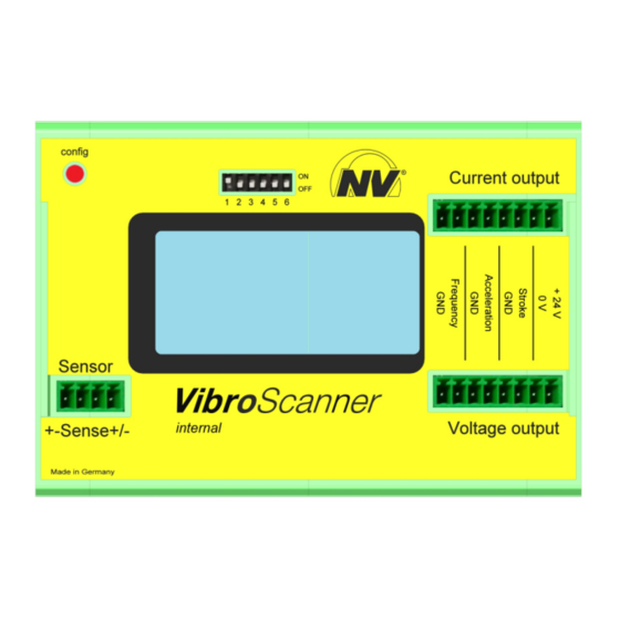
Design and function Design and function Design Element Function Controller/measuring unit Contains the electronic components, the connec- tions and the display. Button: configuration Setting the values shown on the display. Display Shows measured values. DIP-switch Configure controller. Connection terminal: Connect current output and power supply. current output and power supply Connection terminal:... - Page 10 Design and function Basics of A vibration is the periodic variation of a parameter (e. g. displacement of a vibration plate) caused by the fact that a system is displaced from its stable equilib- measurement rium due to a disturbance and forced back towards its original state by a restoring force.
- Page 11 Design and function Root Mean A further important parameter is the Root Mean Square (RMS) or effective Square value. The RMS value of a time-dependent parameter a (t) in a time inter- val T is defined as the root of the sum of the squared measured values which has been divided by the time interval before: In case of a harmonic vibration the RMS is about 71% of the amplitude (exactly...
- Page 12 Design and function Figure: Figure: Spectrum of a sinusoidal vibration with a Spectrum of a random vibration with a domi- frequency of 10 Hz. nant frequency of 10 Hz 1 Power 2 Frequency (Hz) Also for more complex types of vibration it is common use in vibration technology to indicate only one frequency which dominates the system to be measured.
-
Page 13: Transport And Storage
Transport and storage Transport and storage Special conditions of transport are not required. Transport conditions Packaging The VSI are packed ready for installation. The packaging protects the VSI from transport damage. The packaging material has been selected from an environmentally safe and technically disposable point of view and is therefore recyclable. -
Page 14: Installation
Installation Installation Observe the safety instructions in Ch. Safety, from page 5 on. Mount the controller on a standard mounting rail in a suitable control cabi- Mount the net (Degree of protection IP 65). controller Connect the Controller of the VSI requires an operating voltage of 24V DC. controller Depending on the configuration of the DIP switches, the connection is made via the current outputs or voltage outputs. -
Page 15: Start-Up And Operation
Start-up and operation Start-up and operation Observe the safety instructions in Ch. Safety, from page 5 on. Please refer to Ch. Technical data, page 7 for permissible operating condi- Permissible tions. operating conditions Regulations Installation work as well as operation of the system are to be carried out taking the valid accident prevention regulations into account. - Page 16 Start-up and operation Configure the The VSI can be supplied with voltage via the two connection terminals. controller The connection of the power supply and the definition of measuring rang- es depends on the configuration of the DIP switches on the controller. Configuration of the DIP switches Switch 1 OFF = voltage outputs...
-
Page 17: Maintenance And Servicing
Maintenance and servicing Maintenance and servicing Observe the safety instructions in Ch. Safety, from page 5 on. Maintenance of the VSI must be carried out as follows: Maintenance plan Interval Action Monthly Check cables. Every 6 month Check proper condition of connecting cables and plugs. At least every 4 years Check proper condition of electrical systems and stationary electrical equipment. -
Page 18: Troubleshooting
Troubleshooting Troubleshooting Observe the safety instructions in Ch. Safety, from page 5 on. Electrical faults may only be processed by a qualified electrician. Work on Expertise and the VSI may only be carried out by authorised persons. regulations In the case of unauthorised intervention in the VSI there is no longer any Net- warranty claim. -
Page 19: 10 Spare Parts And Accessories
Spare parts and accessories 10 Spare parts and accessories Please provide the following details when ordering spare parts: Ordering of spare parts required amount description and position of spare part type of VSI Spare part list A list of the parts used can be found in the spare part list of the VSI. Requirements Spare parts of the VSI and of the electrical installation must be installed by for exchange...
Need help?
Do you have a question about the VibroScanner VSI and is the answer not in the manual?
Questions and answers