Table of Contents
Advertisement
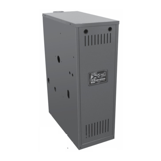
Installation, Operating and Service Instructions for
X-2
Models:
• X-202
• X-206
• X-203
• X-207
• X-204
• X-208
• X-209
• X-205
Manual Contents
Read Before Proceeding . . . . . . . . . . . . . . . . . . . . . . . . . 3
2. User/Homeowner Read Before Proceeding . . . . . . . . . . 4
3. Specifications . . . . . . . . . . . . . . . . . . . . . . . . . . . . . . . . . . 5
4. Locating Boiler . . . . . . . . . . . . . . . . . . . . . . . . . . . . . . . . . 6
5. Preparing Boiler . . . . . . . . . . . . . . . . . . . . . . . . . . . . . . . . . 9
6. Venting . . . . . . . . . . . . . . . . . . . . . . . . . . . . . . . . . . . . . . . . 9
7.
Water Piping . . . . . . . . . . . . . . . . . . . . . . . . . . . . . . . . . . . 12
8. Gas Piping . . . . . . . . . . . . . . . . . . . . . . . . . . . . . . . . . . . . 16
9. Electrical . . . . . . . . . . . . . . . . . . . . . . . . . . . . . . . . . . . . . 17
10. System Start-up and Checkout . . . . . . . . . . . . . . . . . . . 21
11. Operation . . . . . . . . . . . . . . . . . . . . . . . . . . . . . . . . . . . . . 26
12. Before Leaving Jobsite . . . . . . . . . . . . . . . . . . . . . . . . . . 30
13. Service and Maintenance . . . . . . . . . . . . . . . . . . . . . . . . 31
14. How it Works . . . . . . . . . . . . . . . . . . . . . . . . . . . . . . . . . . 34
15. Troubleshooting . . . . . . . . . . . . . . . . . . . . . . . . . . . . . . . 36
16. Service Parts . . . . . . . . . . . . . . . . . . . . . . . . . . . . . . . . . . 41
Appendix B Water Quality and Boiler Additives . . . . . . . . . 49
Appendix C Low Water Return Temperature . . . . . . . . . . . . 50
!
WARNING
Attention Installer - Affix these instructions
adjacent to boiler. Provide model number and
serial number when seeking information and
support.
Attention Building Owner - Retain these
instructions for future reference. Contact a
qualified installer, service agency or gas
supplier for all issues and support.
Read these instructions carefully before installing. This boiler must only be installed, serviced, or repaired
by a qualified installer, service agency or gas supplier. Improper installation, adjustment, alteration, service,
or maintenance can cause severe personal injury, death, or substantial property damage. For assistance or
additional information, consult a qualified installer, service agency or gas supplier.
106636-04 - 8/22
TM
Page
9700609
!
WARNING
• Water Boiler
• Cast Iron
• Chimney Vent
• Gas Fired
Advertisement
Table of Contents

Related Manuals for U.S. Boiler Company X-202


Summary of Contents for U.S. Boiler Company X-202
-
Page 1: Table Of Contents
Installation, Operating and Service Instructions for • Water Boiler • Cast Iron • Chimney Vent • Gas Fired Models: • X-202 • X-206 • X-203 • X-207 • X-204 • X-208 • X-209 • X-205 Manual Contents Page 1. Qualified Installer, Service Agency or Gas Supplier Read Before Proceeding . - Page 2 Installation, Operating & Service Manual The City of New York requires a Licensed Master Plumber supervise the installation of this product. The Massachusetts Board of Plumbers and Gas Fitters has listed the X-2 Series Boiler. See the Massachusetts Board of Plumbers and Gas Fitters website, https://licensing.reg.state.ma.us/pubLic/pl_products/pb_pre_form.asp for the latest Approval Code or ask your local Sales Representative.
-
Page 3: Qualified Installer, Service Agency Or Gas Supplier
Installation, Operating & Service Manual Qualified Installer, Service Agency or Gas Supplier Read Before Proceeding NOTICE: DANGER 1. Size boiler properly. A grossly oversized boiler Asphyxiation Hazard, Burn Hazard, Electrical will cycle excessively leading to premature Shock Hazard. failure of boiler and its components. Warranty •... -
Page 4: User/Homeowner Read Before Proceeding
Installation, Operating & Service Manual User/Homeowner Read Before Proceeding WARNING CAUTION Asphyxiation Hazard. Fire Hazard. Burn Hazard. • A qualified installer, service agency or gas Keep children and pets away from hot surfaces supplier should annually inspect boiler. of the boiler including boiler piping, vent piping, and vent terminals. -
Page 5: Specifications
Installation, Operating & Service Manual Specifications Table 3-1: Ratings DOE Heating Model Input AFUE % Capacity Net AHRI (MBH) Number (MBH) (MBH) X-202 84.0 X-203 84.0 X-204 84.0 X-205 84.0 X-206 84.0 X-207 84.0 X-208 84.0 X-209 84.0 Input ratings can be used for elevations up to 2,000 ft. Refer to System Start-Up and Checkout Sections for elevations 2,000 ft. -
Page 6: Locating Boiler
Installation, Operating & Service Manual Locating Boiler Table 4-1: Corrosive Combustion Contaminants Code Requirements and Sources 1. Installations must conform to requirements of Contaminants to avoid: authority having jurisdiction or, in the Spray cans containing chloro/fluorocarbons (CFC’s) absence of such requirements, to National Fuel Gas Code, ANSI Z223.1/NFPA 54. - Page 7 Installation, Operating & Service Manual Locating Boiler (continued) Before Removing Existing Boiler 4. Place in operation appliance being inspected. Follow Operating Instructions. See Figure 10- Take pictures and measure and/or mark existing 1. Adjust thermo stat so appliance will operate steam and condensate return piping to ensure continuously.
- Page 8 A damaged front air dam will negatively affect the performance of this boiler, which can cause serious property damage, personal injury or death. Model "W" X-202 14 in. X-203 14 in. X-204 16 in. X-205 19 in.
-
Page 9: Preparing Boiler
Installation, Operating & Service Manual Preparing Boiler 4. Remove all boiler hold-down fasteners. DANGER 5. Tilt the boiler to one side and slide a wooden slat Use precautions and appropriate rigging under the two raised feet. apparatus when moving heavy objects. 6. - Page 10 Installation, Operating & Service Manual Venting (continued) 2. Install vent piping. E. Do not connect boiler into a chimney flue servicing an open fireplace or other solid fuel A. See Figure 3-4 for vent sizes and locations. appliance. See Figure 4-2 for clearances. Prior to boiler installation, inspect chimney B.
- Page 11 Installation, Operating & Service Manual Venting (continued) 4. Install vent termination (masonry chimney and DANGER single wall metal pipe). Inspect existing chimney before installing A. Termination shall extend at least 5 ft. boiler. Look for corrosion holes. Failure to clean in vertical height above highest connected chimney or replace corroded pipe or tile lining appliance vent outlet.
-
Page 12: Water Piping
Installation, Operating & Service Manual Venting (continued) Roof Slope Heights (H) Roof Slope Flat to 6/12 Over 6/12 to 7/12 1.25 Over 7/12 to 8/12 Over 8/12 to 9/12 Over 9/12 to 10/12 Over 10/12 to 11/12 3.25 Over 11/12 to 12/12 Over 12/12 to 14/12 Over 14/12 to 16/12 Over 16/12 to 18/12... - Page 13 Installation, Operating & Service Manual Water Piping (continued) 4. Connect system supply and return piping to boiler. Refer to Figures 7-1, 7-2, and 7-3. Also consult Residential Hydronic Heating Installation and Design I=B=R Guide. Maintain minimum ½ inch clearance from hot water piping to combustible materials.
- Page 14 Installation, Operating & Service Manual Water Piping (continued) 106636-04 - 8/22...
- Page 15 Installation, Operating & Service Manual Water Piping (continued) 106636-04 - 8/22...
-
Page 16: Gas Piping
Installation, Operating & Service Manual Gas Piping DANGER Explosion Hazard. 1. Size gas piping. Design system to provide • Do not use matches, candles, open flames, or adequate gas supply to boiler. Consider these other ignition sources to check for leaks. Failure factors: to comply could result in severe personal injury, A. -
Page 17: Electrical
Installation, Operating & Service Manual Electrical WARNING DANGER Electrical Shock Hazard. Wiring errors can Electrical Shock Hazard. cause improper or dangerous operation. Verify • Disconnect electrical supply before installing or proper operation after installation. performing maintenance. 1. Install wiring so boiler is electrically bonded •... - Page 18 Installation, Operating & Service Manual Electrical (continued) Figure 9-1: Wiring Connection Diagram 106636-04 - 8/22...
- Page 19 Installation, Operating & Service Manual Electrical (continued) Figure 9-2: Schematic Ladder Diagram 106636-04 - 8/22...
- Page 20 Installation, Operating & Service Manual Electrical (continued) Figure 9-3: Wiring Schematic, Zone Valves Figure 9-4: Wiring Schematic, Zone Circulators 106636-04 - 8/22...
-
Page 21: System Start-Up And Checkout
Installation, Operating & Service Manual System Start-up and Checkout Open zone valve or start circulator to second DANGER zone to be purged, then close first. Explosion Hazard. Repeat this step until all zones have Do not use matches, candles, open flames, or been purged, but always have one zone other ignition sources to check for leaks. - Page 22 Installation, Operating & Service Manual System Start-up and Checkout (continued) Figure 10-1: Operating Instructions 106636-04 - 8/22...
- Page 23 Installation, Operating & Service Manual System Start-up and Checkout (continued) LP Gas Only. Pilot burner produces three (3) WARNING flames. The center flame should be steady, Explosion Hazard. medium hard blue enveloping 3/8 to 1/2 inch of Ensure inlet pressure tapping is fully closed sending probe.
- Page 24 Boiler Rating 10,000 5,000 ft. 7,000 ft. monoxide hazard. Model Label X-202 30.5 27.5 10. Check gas inlet pressure. X-203 A. While boiler and all other gas appliances X-204 are not firing, gas inlet pressure should not X-205 exceed ½...
- Page 25 Installation, Operating & Service Manual System Start-up and Checkout (continued) 13. Measure carbon monoxide (CO) level in vent after 5 minutes of main burner operation. CO should not exceed 400ppm air free. 14. Check vent damper operation. Vent damper must be in open position when appliance main burners are operating.
-
Page 26: Operation
Installation, Operating & Service Manual Operation Table 11-1: Sequence of Operation 1. Boiler Sequence of Operation (See Table 11-1). A. When thermostat calls for heat, control starts Status Codes displayed in STA Mode system circulator. Status Description Standby B. If thermostat is not satisfied with residual (Burner off No call for heat detected heat in boiler, or boiler water temperature is... - Page 27 Installation, Operating & Service Manual Operation (continued) Viewing the Operating Mode Options. Table 11-3 In operating mode, user may view (but not Adjustable Parameters change) boiler operating status, settings and Default Range Description troubleshooting information. 180oF 140-220°F Adjust High Limit Setting For example, when “I ”...
- Page 28 Installation, Operating & Service Manual Operation (continued) Table 11-5: Circulator Pre-purge Time example, 6. More Information About Adjustable Parameters. (PP_ = 2 minutes) A. High Limit (HL_) Burner turns "off" when boiler water Call for Boiler Heat Terminal Burner Status temperature (bt) is above this value.
- Page 29 Installation, Operating & Service Manual Operation (continued) G. Domestic Hot Water (DHW) Terminal Function (dh_) ii. Second heating zone (dh_ is set to second heating zone (tt2)). DHW Circulator output can be connected to a domestic hot water circulator or a second Helpful when home uses only two heating heating zone circulator.
-
Page 30: Before Leaving Jobsite
Installation, Operating & Service Manual Before Leaving Jobsite Before Leaving Jobsite: Boiler and system filled with water Performed gas leak test Checked pilot burner flame Checked main burner flames Checked gas input rate Checked gas inlet pressure ... -
Page 31: Service And Maintenance
Installation, Operating & Service Manual Service and Maintenance Important Product Safety Information: Refractory Ceramic Fiber Product WARNING Some boiler components use materials that contain refractory ceramic fibers (RCF). RCF has been classified as a possible human carcinogen. When exposed to elevated temperatures, RCF may change into crystalline silica, a known carcinogen. - Page 32 Installation, Operating & Service Manual Service and Maintenance (continued) WARNING This boiler should be serviced by a qualified installer, service agency, or gas supplier. Inspections should be performed at intervals specified in this manual. Maintain manual in a legible condition. •...
- Page 33 Installation, Operating & Service Manual Service and Maintenance (continued) 6. Inspect Temperature/Pressure Gauge. 4. Clean Main Burners and Combustion Chamber. A. Water temperature needle should move with A. To remove burners for cleaning, changing variation in water temperature. orifices, or repairs: B.
-
Page 34: How It Works
Installation, Operating & Service Manual How It Works X-2 boilers are equipped with an Intelligent Hydronic Control. This control combines features such as ignition control, high limit switch, and circulator relays. Energy is saved by using a thermal purge feature that starts the circulator and delays burner start when residual heat is available in boiler. - Page 35 Installation, Operating & Service Manual How It Works (continued) Rear of Boiler (On rear of boiler) 106636-04 - 8/22...
-
Page 36: Troubleshooting
Installation, Operating & Service Manual Troubleshooting 1. Before Troubleshooting. 2. IDL 1200 LWCO: Amber "LOW WATER" LED indicates the boiler is not sensing water in boiler. When using troubleshooting tables, keep in mind: A. If AMBER LED is ON and boiler is filled with A. - Page 37 Installation, Operating & Service Manual Troubleshooting (continued) 3. Use Control Display ERR (ERROR) Number To Direct Troubleshooting Efforts. If control detects an error it will flash “Err” (ERROR) followed by a number. Use this number to identify boiler problem and corrective action in table below. If there is no Err display, proceed to Troubleshooting Section D: Display Status Recommended Corrective Action...
- Page 38 Installation, Operating & Service Manual Troubleshooting (continued) 4. Use STA (STATUS) Number To Guide Troubleshooting. The control will flash “STA” followed by a number. Use this number to identify the boiler problem in table below: 1. Boiler and Circulator Off Display / Status Recommended Corrective Action Boiler has not detected a call for heat (tt = ff and dh = ff).
- Page 39 Installation, Operating & Service Manual Troubleshooting (continued) 5. Circulator is On But Damper is Not Open Display / Status Recommended Corrective Action Control is waiting for damper to open. Damper end switch has failed to close (end switch contact is stuck open). Combustion can never take place unless damper blade is in the fully open position.
- Page 40 Installation, Operating & Service Manual Troubleshooting (continued) 6. Circulator is On, Damper is Open But Boiler Fails to Start (continued) Display / Status Recommended Corrective Action 1. No Spark a. Can you hear sparking while STA 6 is displayed? - If there is no spark noise, replace the control. b.
-
Page 41: Service Parts
All X-2 Series Service Parts may be obtained through your local U.S. Boiler Company Wholesale distributor. Should you require assistance in locating a U.S. Boiler Company Distributor in your area, or have questions regarding the availability of U.S. Boiler Company products or service parts, please contact U.S. Boiler Company Customer Service at (717) 481-8400 or Fax (717) 481-8408. - Page 42 Installation, Operating & Service Manual Service Parts (continued) Part Number [Quantity] Description X-202 X-203 X-204 X-205 X-206 X-207 X-208 X-209 Base Wrapper Base Tray Burner Tray (Nat Gas) (Nat Gas) (Nat Gas) (Nat Gas) (Nat Gas) (Nat Gas) (Nat Gas)
- Page 43 Installation, Operating & Service Manual Service Parts (continued) Natural Gas Only Part Number [Quantity] Description X-202 X-203 X-204 X-205 X-206 X-207 X-208 X-209 Gas Valve (Natural Gas), 109620-01 [1] Honeywell VR8204C3007 Gas Valve (Natural Gas), 109622-01 [1] Honeywell VR8304P4496 Gas Valve (LP Gas),...
- Page 44 Installation, Operating & Service Manual Service Parts (continued) Part Number [Quantity] Key No. Description X-202 X-203 X-204 X-205 X-206 X-207 X-208 X-209 Control 103966-02 [1] Transformer 106034-01 [1] Temperature Sensor/LWCO 106495-02 [1] Temperature Sensor (Models Not Shown 109645-01 [1] without LWCO)
- Page 45 Installation, Operating & Service Manual Service Parts (continued) Part Number [Quantity] Description X-202 X-203 X-204 X-205 X-206 X-207 X-208 X-209 Jacket Wrap-around Jacket 106357-03 [1] 106357-04 [1] 106357-05 [1] 106357-06 [1] 106357-07 [1] 106357-08 [1] 106357-09 [1] Panel Jacket Vestibule Panel...
- Page 46 Installation, Operating & Service Manual Service Parts (continued) Part Number [Quantity] Description X-202 X-203 X-204 X-205 X-206 X-207 X-208 X-209 Supply Water Manifold 109614-01 [1] Temperature/Pressure Gauge 105894-01 [1] 30 PSI Relief Valve 109038-01 [1] Drain Valve Obtain Locally (3/4 in. NPT boiler connection)
- Page 47 Installation, Operating & Service Manual Service Parts (continued) Part Number [Quantity] Key No. Description X-202 X-203 X-204 X-205 X-206 X-207 X-208 X-209 Power Supply Harness 109639-01 [1] Main Control Harness 109640-01 [1] Accessories: Part Number [Quantity] Key No. Description X-202...
-
Page 48: Appendix A Combination Refrigeration/Heating System
Installation, Operating & Service Manual Appendix A Combination Refrigeration/ Heating System 1. If boiler is used in connection with refrigeration 2. If boiler is connected to heating coils located in systems, boiler must be installed with chilled air handling units where they may be exposed to medium piped in parallel with the heating boiler refrigerated air, boiler piping must be equipped using appropriate valves to prevent chilled... -
Page 49: Appendix B Water Quality And Boiler Additives
Installation, Operating & Service Manual Appendix B Water Quality and Boiler Additives Other non-metallic tubing is equipped with an The heat exchanger used in this boiler is made from oxygen barrier to prevent migration of oxygen cast-iron. Once filled with water, it will be subjected into water. -
Page 50: Appendix C Low Water Return Temperature
Installation, Operating & Service Manual Appendix C Low Return Water Temperatures Thermal Shock: Cast iron boilers are very robust. 110oF and below return water temperatures will not cause thermal shock to U.S. Boiler castings. Condensation is a different matter: Cast iron boilers will tolerate intermittent periods of condensation, but are not designed for extended condensation periods. - Page 51 Installation, Operating & Service Manual Appendix C Low Return Water Temperatures (continued) Primary-Secondary Pumping: This is an improvement over simple by-pass piping to reduce condensation. Again this is a fixed system. It can not adapt to variations in temperature and flow. Best Alternative: U.S.
- Page 52 Installation, Operating & Service Manual U.S. Boiler Company, LLC P.O. Box 3020 Lancaster, PA 17604 1-888-432-8887 www.usboiler.net 106636-04 - 8/22...