Table of Contents
Advertisement
Quick Links
IMPORTANT SAFETY INFORMATION: Always read this manual first
before attempting to install or use this fireplace. For your safety, always
comply with all warnings and safety instructions contained in this manual
to prevent personal injury or property damage.
To view the full line of Empire products, please visit
www.empirecomfort.com
Owner's Manual
Model
EBL74-1
UL File E71416
# 6909610100
7214000200R06
Advertisement
Table of Contents

Related Manuals for Empire Comfort Systems EBL74-1


Summary of Contents for Empire Comfort Systems EBL74-1
- Page 1 Owner’s Manual Model EBL74-1 UL File E71416 # 6909610100 IMPORTANT SAFETY INFORMATION: Always read this manual first before attempting to install or use this fireplace. For your safety, always comply with all warnings and safety instructions contained in this manual to prevent personal injury or property damage.
-
Page 2: Table Of Contents
Table of Contents Welcome & Congratulations ....3 IMPORTANT INSTRUCTIONS ....4 Quick Reference Guide . -
Page 3: Welcome & Congratulations
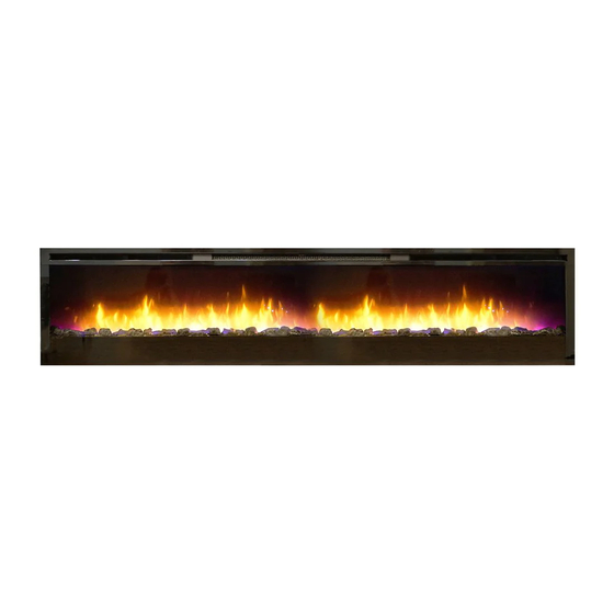
Welcome & Congratulations Thank you and congratulations for purchasing an electric fireplace from Empire. Serial Number Rating Label with Label Model Number Please carefully read and save these instructions. CAUTION: Read all instructions and warnings carefully before starting installation. Failure to follow these instructions may result in a possible electric shock, fire hazard and will void the warranty. -
Page 4: Important Instructions
IMPORTANT INSTRUCTIONS When using electrical appliances, ⑥ Do not operate the unit after basic precautions should always it malfunctions. Disconnect power be followed to reduce the risk of at the service panel and contact fire, electric shock, and injury to your dealer. - Page 5 IMPORTANT INSTRUCTIONS ⑭ Use this heater only as WARNING: Remote control described in this manual. Any contains small batteries. Keep other use not recommended by away from children. If swallowed, the manufacturer may cause fire, seek medical attention immedi- electric shock or injury to persons. ately.
-
Page 6: Quick Reference Guide
Quick Reference Guide 1. The electrical information Figure 1 regarding your electric fireplace can be found on the rating label [7.1 in.] located on the front of the unit, behind the glass. 2. If you have any technical questions or concerns regarding the operation of your electric fireplace, or require service, contact a service person or... -
Page 7: Fireplace Installation
Fireplace Installation Site Selection WARNING: To reduce the risk of fire, do not store or use gasoline Review and consider all of the fol- or other flammable vapors or liq- lowing conditions before installation: uids in the vicinity of the heater. •... -
Page 8: Wiring
Fireplace Installation Wiring bracket. 3. Remove the cover off of the WARNING: To reduce the risk unit at the front to access the of fire, electric shock or injury to wire connections. (Figure 3) persons, always use a licensed electrician. WARNING: Ensure that the Figure 2 circuit on which the fireplace is... - Page 9 Fireplace Installation For 120V Installations Figure 3 Use two conductor, non-metallic sheath cable with ground wire (3 wires total) for the incoming power supply. CAUTION: Use the appropri- ate wire to meet local and national electrical codes for rated power consumption. •...
-
Page 10: Surface Mount Installation
Fireplace Installation Surface Mount Installation For 240V Installations Use three conductor, non-metallic CAUTION: Two people will be sheath cable with ground wire required for various steps of (4 wires total) for the incoming this procedure. power supply on fireplace inserts. WARNING: Ensure that the CAUTION: Use the appropri- circuit on which the fireplace is... - Page 11 Fireplace Installation the screw (predrill if required). Figure 5 5. Secure the wall bracket to the wall using the supplied 1½ in. (3.8 cm) mounting screws and washers into the wall and/or wall anchors. 6. Install the bottom support brack- et to the wall centered with the wall mounting bracket, using the appropriate mounting hardware,...
-
Page 12: Flush Mounted Installation - 2X8 Framing
Fireplace Installation Flush Mounted Installation - screws through the four mount- ing holes located on the inside 2x8 Framing surface of the fireplace chassis, CAUTION: Two people will be into wall studs (Figure 8). required for various steps of this 5. -
Page 13: Front Glass Installation
Front Glass Installation Figure 9 1. Pour and evenly distribute the Front tray supplied media in the Media tray of the firebox (Figure 9). 2. Carefully mount front glass assembly so that the front glass hooks hang on the front Front glass glass mounts on the fireplace assembly... -
Page 14: Operation
Operation Figure 11 Figure 12 Floating Display • The unit will turn on with the WARNING: This electric fire- same functions that it was set box must be properly installed to when it was turned Off and before it is used. the intake temperature will The unit can be controlled by be indicated on the Floating... - Page 15 Operation to decrease the setpoint and • Indicated by the icon and the intake temperature be- to increase the setpoint ing displayed on the Floating on the unit or the remote. Display , for 5 seconds before • The Floating Display will in- turning off.
- Page 16 Operation → Changed by repeatedly press- → To set the timer press the timer ing the corresponding button button on the remote, repeat- on the remote or the unit. edly, until the desired time is displayed. • Cycles through the different preset ambient lighting settings •...
-
Page 17: Maintenance
Operation Remote Control Battery CR2025) battery in the battery holder. Replacement 3. Close the battery cover. To replace the battery: Battery must be recycled 1. Slide battery cover open on or disposed of properly. the remote control. Check with your Local 2. -
Page 18: Replacement Parts
Replacement Parts Element ..........EF2200510700RP Partially Reflective Glass . -
Page 19: Warranty
Warranty (mantels) and trims also applies to any Products to which this limited warranty implied warranties that may exist under applies applicable law. Some jurisdictions do not This limited warranty applies to your newly allow limitations on how long an implied purchased Empire electric fireplace. - Page 20 Warranty limited warranty services. ANY THIRD PARTY. WHETHER IN CON- TRACT, IN TORT, OR ON ANY OTHER • For products other than surrounds BASIS, FOR ANY INDIRECT, SPECIAL, (mantels) and trims, this 2 year limited PUNITIVE, EXEMPLARY, CONSEQUEN- warranty entitles the purchaser to on- TIAL, OR INCIDENTAL LOSS, COST, site or in-home warranty services.
-
Page 21: Technical Support
Empire Comfort Systems Inc. Belleville, IL If you have general questions about our products, please e-mail us at info@empirecomfort.com. If you have a service or repair question, please contact your dealer.
Need help?
Do you have a question about the EBL74-1 and is the answer not in the manual?
Questions and answers