Table of Contents
Advertisement
Advertisement
Table of Contents
Troubleshooting

Related Manuals for Empire Comfort Systems VFP20IN23L


Summary of Contents for Empire Comfort Systems VFP20IN23L
- Page 1 This Owner's Manual is provided and hosted by Appliance Factory Parts. EMPIRE VFP20IN23L Owner's Manual Shop genuine replacement parts for EMPIRE VFP20IN23L Find Your EMPIRE Fireplace Parts - Select From 642 Models -------- Manual continues below --------...
- Page 2 INSTALLATION INSTRUCTIONS AND OWNER’S MANUAL Vent Free Fireplace Insert UNVENTED GAS FIREPLACE MODELS VFP20IN3(0,1,2,3)L10(N,P)-1 VFP20IN73L10(N,P)-1 VFP20IN2(0,1,2,3)L(N,P)-1 VFP20IN3(0,1,2,3)L(N,P)-1 VFP20IN73L(N,P)-1 GAS-FIRED VFP28IN2(0,1,2,3)L(N,P)-1 VFP28IN3(0,1,2,3)L(N,P)-1 VFP28IN73L(N,P)-1 INSTALLER: WARNING Leave this manual with the appliance. If not installed, operated and maintained CONSUMER: in accordance with the manufacturer’s Retain this manual for future reference.
-
Page 3: Table Of Contents
TABLE OF CONTENTS SECTION PAGE Important Safety Information ............................3 Safety Information For Users Of Propane Gas ......................4 Important Installation Guidelines ........................... 5 Introduction ..................................6 Specifications................................. 7 Installation In A Fireplace ............................... 8 Fireplace Insert Dimensions ............................9 Built-In Fireplace Installation............................ -
Page 4: Important Safety Information
IMPORTANT SAFETY INFORMATION DANGER: Indicates a hazardous situation which, if not avoided, will • WARNING: DO NOT operate this appliance unless all result in death or serious injury. components including logs, burners, and controls are in good working condition. Never operate this appliance if any log or WARNING: Indicates a hazardous situation which, if not avoided, twig is broken, or out of their intended position. -
Page 5: Safety Information For Users Of Propane Gas
SAFETY INFORMATION FOR USERS OF PROPANE GAS Propane Gas is a flammable gas which can cause fires and SOME POINTS TO REMEMBER explosions. In its natural state, propane is odorless and color- • Learn to recognize the odor of Propane Gas. Your local less. -
Page 6: Important Installation Guidelines
IMPORTANT INSTALLATION GUIDELINES PROPER LOG PLACEMENT CEILING FANS, PORTABLE FANS OR LOGS INSTALLED NEAR COLD AIR RETURNS Log placement is critical to proper burner performance. Logs must be correctly positioned onto the burner. The photos in this manual Ceiling fans or oscillating floor type fans need to be monitored show the proper pinned position for logs on this set. -
Page 7: Introduction
INTRODUCTION Instructions to Installer Installation on Rugs and Tile Installer must leave instruction manual with owner after If this appliance is installed directly on carpeting, tile or other installation. combustible material other than wood flooring the appliance shall 2. Installer must have owner fill out and mail warranty card supplied be installed on a metal or wood panel extending the full width and with unvented room heater. -
Page 8: Specifications
SPECIFICATIONS VFP28IN3*L Propane Natural DECORATIVE SURROUNDS AND FRONTS (1 REQUIRED) Input Btu/hr Maximum 28,000 28,000 Model Description Use On Contemporary Btu/hr Minimum 20,000 20,000 Orifice S256BL Black Surround, 6" Wide Sides VFP20IN Air Shutter Opening Full Open 1/8” S336BL Black Surround, 6" Wide Sides VFP28IN VFP28IN2*L Propane Natural S253BL Black Surround, 3" Wide Sides VFP20IN... -
Page 9: Installation In A Fireplace
INSTALLATION IN A FIREPLACE 1. Before beginning, remove door and log package from unit. NOTICE: The following statement is also provided on a separate Also check to make sure there is no hidden damage to the label plate in the instruction packet. Prior to installation of the fire- unit. Take a minute and plan out the gas and electrical route. It place insert, the installer must mechanically secure this warning is best to start with the gas line first, followed by the electrical plate to the inside of the fireplace for future reference as required. -
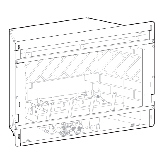
Page 10: Fireplace Insert Dimensions
FIREPLACE INSERT DIMENSIONS When planning a fireplace insert installation, it’s necessary to • Electrical supply requirements for blower. (120V, 60Hz, 1 Amp) determine: • Proper opening size of fireplace required for installation of • Gas supply piping. the fireplace insert. • Electrical connections • Whether optional accessories - devices such as a wall switch or remote control - are desired. VF FIREPLACE INSERT DIMENSIONS Model VFP20IN 19 3/4" 18 5/16" 13 3/4" 29 1/4" 25 1/2" 16 1/8" VFP28IN 22 3/4"... -
Page 11: Built-In Fireplace Installation
BUILT-IN FIREPLACE INSTALLATION In planning the installation for the fireplace, it is necessary to If the fireplace is installed directly on carpeting, tile or other determine where the unit is to be installed and whether optional combustible material other than wood flooring, it should be accessories are desired. -
Page 12: Vfp20In Fireplace With Surround Dimensions
VFP20IN FIREPLACE WITH SURROUND DIMENSIONS DF20MBL 40” 1 3/4” 25 5/8” 15/16” DF20LBL 34” 4 1/4” 11 1/2” 20 1/2” 25” DF20GBL 29829-21-0918 Page 11... -
Page 13: Vfp28In Fireplace With Surround Dimensions
VFP28IN FIREPLACE WITH SURROUND DIMENSIONS DF28MBL 43” 1 3/4” 28 5/8” 15/16” DF28LBL 37” 4 1/4” 14 1/2” 23 1/2” 28” DF28GBL Page 12 29829-21-0918... -
Page 14: Water Vapor: A By-Product Of Unvented Room Heaters
WATER VAPOR: A BY-PRODUCT OF UNVENTED ROOM HEATERS Water vapor is a by-product of gas combustion. An unvented room The following steps will help insure that water vapor does not heater produces approximately one (1) ounce (30ml) of water for become a problem. every 1,000 BTU's (.3KW's) of gas input per hour. 1. Be sure the heater is sized properly for the application, including ample combustion air and circulation air. - Page 15 PROVISIONS FOR ADEQUATE COMBUSTION & VENTILATION AIR (CONT'D) The space in the above example is a confined space because the VENTILATION AIR FROM OUTDOORS (Figure 6) actual BTU/Hr used is more than the maximum BTU/HR the space Provide extra fresh air by using ventilation grills or ducts. You must can support. You must provide additional fresh air. Your options provide two permanent openings: one within 12"...
-
Page 16: Gas Supply
GAS SUPPLY The gas pipeline can be brought in through the right or left side of Installing the Main Gas Shut-Off the appliance. The insert has a Flexline with shutoff valve located on Each appliance should have its own manual gas shut-off. the right side when facing the unit. -
Page 17: Clearances
GAS SUPPLY (CONT'D) CHECKING MANIFOLD PRESSURE Propane Gas will have a manifold pressure approximately 10.0"w.c. MILLIVOLT VALVES at the pressure regulator outlet with the inlet pressure to the pressure Natural Gas will have a manifold pressure of approximately 3.5" w.c. regulator from a minimum of 11.0"w.c. - Page 18 CLEARANCES (CONT'D) FINISHED WALL FLAT MANTEL SHELF 12” 10” 8” 6” 4” 21” 19” 2” 17” 15” 13” 11” VFP20 Series Figure 11 FINISHED WALL FLAT MANTEL SHELF 12” 10” 8” 6” 4” 26” 24” 2” 22” 20” 18” 16” VFP28 Series Figure 12 29829-21-0918 Page 17...
- Page 19 CLEARANCES (CONT'D) Figures 13 and 14 pertain to VFP(20,28)IN Series. CEILING NO MANTEL 26” MIN. TOP OF FIREPLACE OPENING FLOOR Surround Clearances Figure 13 CEILING NO MANTEL 26” MIN. TOP OF FIREPLACE OPENING FLOOR Glass Front Clearances Figure 14 Page 18 29829-21-0918...
-
Page 20: Combustible Materials
COMBUSTIBLE MATERIALS Do not attach combustible material to the mantel of your fireplace. No greeting cards, stockings or ornamentation of any type should be This is a fire hazard. placed on or attached to the fireplace. This is a heating appliance. The flow of heat can ignite combustibles. Figure 15 Figure 16 29829-21-0918 Page 19... -
Page 21: Alternate On/Off Switch Installation
ALTERNATE ON/OFF SWITCH INSTALLATION WIRING THE FIREPLACE Find the coiled low voltage wire assembly and ON/OFF switch located in the instruction packet. NOTICE: Electrical wiring must be installed by a licensed electrician. Attach the flag terminal ends to the “TH/TP” and “TH” terminals CAUTION: Disconnect remote controls if you are absent for on the front terminal block of the gas valve. See Figure 19. extended time periods. - Page 22 ALTERNATE ON/OFF SWITCH INSTALLATION (CONT'D) WIRING THE FIREPLACE Attach the surround panel assembly to the insert. Place the surround panel assembly against the face of the insert and WARNING align the lower retaining tabs with the notches on the insert sides.
-
Page 23: Surround Panel Installation
SURROUND PANEL INSTALLATION INSTALLING THE TRIM SURROUNDS Combustible materials MUST NEVER overlap onto the front face. WARNING: when finishing the fireplace insert, never ob- struct or modify the air inlet/outlet louvers on the fire- place insert in any manner. NOTE: INSTALL SURROUND PANELS SO THAT THE TOP PANEL RETURN FLANGE SLIDE’S OVER THE TOP FLANGE ON... -
Page 24: Blower Accessory Information
BLOWER ACCESSORY INFORMATION The appliance, when installed must be electrically con- THE FAN CONTROL SWITCH IS CLIPPED BETWEEN THE BURNER nected and grounded in accordance with local codes or, BASE AND VALVE BRACKET BLOWER ASSEMBLY in the absence of local codes. National Electrical Code, ANSI/NFPA No. -
Page 25: Vfp20In Log Placement
Application of excess loose material (glowing embers) may adversely affect performance of the heater. Rock wool can be added to burners for a glowing ember effect. Apply loose material (glowing embers) only on locations shown on Page 25. Replacement of loose material (glowing embers) must be purchased from Empire Comfort Systems, Inc. Application of excess loose material (glowing embers) may adversely affect performance of the heater. Page 24 29829-21-0918... -
Page 26: Vfp20In Ember Placement Photos
VFP20IN EMBER PLACEMENT PHOTOS 29829-21-0918 Page 25... -
Page 27: Vfp28In Log Placement
Rock wool can be added to burners for a glowing ember effect. Log Placement Apply loose material (glowing embers) only on locations shown on Figure 27 Page 27. Replacement of loose material (glowing embers) must be purchased from Empire Comfort Systems, Inc. Application of excess The following WARNING applies when log set is installed onto an loose material (glowing embers) may adversely affect performance unvented gas burner assembly. of the heater. -
Page 28: Vfp28In Ember Placement Photos
VFP28IN EMBER PLACEMENT PHOTOS 29829-21-0918 Page 27... -
Page 29: Hydraulic Thermostat Lighting Instructions
HYDRAULIC THERMOSTAT LIGHTING INSTRUCTIONS FOR YOUR SAFETY READ BEFORE LIGHTING WARNING If you do not follow these instructions exactly, a fire or explosion may result causing property damage, personal injury or loss of life. A. This appliance has a pilot which must be lit by hand. When C. -
Page 30: Millivolt Control Valve Lighting Instructions
MILLIVOLT CONTROL VALVE LIGHTING INSTRUCTIONS FOR YOUR SAFETY READ BEFORE LIGHTING WARNING If you do not follow these instructions exactly, a fire or explosion may result causing property damage, personal injury or loss of life. A. This appliance has a pilot which must be lit by hand. When C. -
Page 31: 10,000 Btu Millivolt Control Valve Lighting Instructions
10,000 BTU MILLIVOLT CONTROL VALVE LIGHTING INSTRUCTIONS FOR YOUR SAFETY READ BEFORE LIGHTING WARNING If you do not follow these instructions exactly, a fire or explosion may result causing property damage, personal injury or loss of life. A. This appliance has a pilot which must be lighted by C. -
Page 32: Intermittent Pilot Lighting Instructions
INTERMITTENT PILOT LIGHTING INSTRUCTIONS FOR YOUR SAFETY READ BEFORE LIGHTING WARNING If you do not follow these instructions exactly, a fire or explosion may result causing property damage, personal injury or loss of life. A. This appliance has a pilot which must be lighted by hand. When C. Use only your hand to push in or turn the gas control knob. -
Page 33: Operation Instructions/Flame Appearance
OPERATION INSTRUCTIONS/FLAME APPEARANCE PERIODIC CLEANING – Refer to parts diagram for location of Flames from the pilot (rear right back side of the pan burner) as well as the main flame should be visually checked as the log set items discussed below. is installed. • Do not use cleaning fluid to clean logs or any part of heater. • Logs - brush with soft bristle brush or vacuum with brush In normal operation at full rate after 10 to 15 minutes, the flame attachment. appearance should be sets of yellow flames. • Remove loose particles and dust from the burner areas, NOTICE: All flames will be random by design, flame height will go controls, piezo covers and grate. Don’t remove ceramic media up and down. -
Page 34: Pilot Flame Characteristics
PILOT FLAME CHARACTERISTICS Figures 28, 30 and 32 show a correct pilot flame pattern. The HYDRAULIC THERMOSTAT PILOT correct flame will be blue and will extend beyond the thermocouple. Correct Pilot Flame Pattern PILOT The flame will surround the thermocouple just below the tip. A slight yellow flame may occur where the pilot flame and main burner flame meet. Figures 29, 31 and 33 show an incorrect pilot flame pattern. The incorrect pilot flame is not touching the thermocouple. This will cause the thermocouple to cool. When the thermocouple cools, the heater will shut down. - Page 35 PILOT FLAME CHARACTERISTICS INTERMITTANT PILOT Cleaning and Pilot Maintenance Oxygen Depletion Sensor Pilot (Figures 34, 35 and 36) Correct Pilot Flame Pattern When the pilot has a large yellow tip flame, clean the Oxygen IGNITOR Depletion Sensor as follows: Clean the ODS pilot by loosening nut B from the pilot tubing. SENSOR When this procedure is required, grasp nut A with an open end wrench.
-
Page 36: Wiring
WIRING Label all wires prior to disconnection when servicing controls. Wiring Remote Receiver errors can cause improper and dangerous operation. Verify proper Use the following steps to place the remote receiver adjacent to operation after servicing. the gas valve. Attention: The remote receiver bracket is not used in this Millivolt thermopile is self powered, gas valve does not require 110 installation. -
Page 37: Troubleshooting Symptoms - Possible Causes And Corrections
TROUBLESHOOTING SYMPTOMS - POSSIBLE CAUSES AND CORRECTIONS Turn appliance OFF and allow to cool before servicing. Only a qualified service person should service and repair the heater. When ignitor button is pressed, there is no spark at ODS/ Thermocouple connection loose at control valve - Hand tighten until snug, then tighten 1/4 turn more. pilot. e. Pilot flame not touching thermocouple, which allows Ignitor electrode positioned wrong - Replace pilot. -
Page 38: Ipi Electronic System Operating Instructions
IPI ELECTRONIC SYSTEM OPERATING INSTRUCTIONS 5.25 VDC ELECTRONIC CONTROL VALVE Follow the SAFETY and LIGHTING INSTRUCTIONS for In- termittent Pilot controls found in this manual, and on labels The electronic control valve system includes the ability to switch found in the control compartment located in the lower cavity the pilot from a standing pilot mode to an intermittent pilot mode. -
Page 39: Ipi Electronic System Wiring Diagram
IPI ELECTRONIC SYSTEM WIRING DIAGRAM BLUE BLUE GREEN WHITE WHITE ORANGE CPI/IPI SWITCH ON/OFF REMOTE RECEIVER PILOT SWITCH (OPTIONAL) YELLOW + ON REMOTE - OFF BLACK BLACK GAS CONTROL VALVE (GND) WHITE GREEN BLACK AC/DC POWER ADAPTOR BLACK ELECTRONIC CONTROL MODULE BATTERY HOLDER If any of the original wire as supplied with this unit must be replaced, it must be replaced with equivalent gauge and temperature rated wire. -
Page 40: Intermittent Control System Troubleshooting
INTERMITTENT CONTROL SYSTEM TROUBLESHOOTING Brief Description of the Components The gas valve is equipped with a manual HI/LO knob to allow for manual modulation of the gas outlet pressure. The manual HI/LO knob can be replaced by an Empire Comfort Systems Variable Remote Kit. WARNING This appliance is equipped for (Natural or Propane Gas). Field conversion is not permitted. -
Page 41: Intermittent Control System Troubleshooting
INTERMITTENT CONTROL SYSTEM TROUBLESHOOTING If the DFC giving signal lock out: Verify the electrical connections’ integrity and The board should be unlocked to make sure they are in accordance with the relevant reinitiate a pilot flame ignition (for Is the DFC board in system wiring diagram. - Page 42 INTERMITTENT CONTROL SYSTEM TROUBLESHOOTING Replace DFC board. Main burner lights when the pilot only Replace the gas valve. should light. Verify the pilot flame fully engulfs the tip of the sense electrode. If not replace the pilot assembly. Replace the pilot assembly. Carefully clean the electrical connections of the sense cable, and the DFC board sense cable connection.
-
Page 43: Vfp20In Parts List
33411 SWITCH ASSEMBLY 29376 PILOT BRACKET R2204 CORD SET 29377 VALVE BRACKET R7912 WIRE HARNESS, FAN CONTROL R2522 ON/OFF SWITCH VFP20IN23L 29903 SWITCH BRACKET P265 ORIFICE #42 - NATURAL 29813 INLET TUBING ASSEMBLY P182 ORIFICE #53 - PROPANE TUBING ASSEMBLY 33809 R5171 PILOT, NATURAL... -
Page 44: Vfp20In Parts View
VFP20IN PARTS VIEW HYDRAULIC VALVE ASSEMBLY MILLIVOLT VALVE ASSEMBLY INTERMITTENT PILOT (IP) VALVE ASSEMBLY 29829-21-0918 Page 43... -
Page 45: Vfp28In Parts List
VFP28IN PARTS LIST INDEX PART INDEX PART DESCRIPTION DESCRIPTION COMMON PARTS 26170 PILOT TUBING ASSEMBLY (NATURAL) VFP28IN33 28053 FIREBOX UPPER BAFFLE R3624 PILOT (NATURAL) 26157 FIREBOX BAFFLE R3623 PILOT (PROPANE) 21642 BRICK LINER BRACKET R9196 BRICK PANEL, BACK P203 ORIFICE #38 (NATURAL) P185 ORIFICE #52 (PROPANE) R9198 BRICK PANEL, RIGHT SIDE R3626 VALVE (NATURAL) R9197 BRICK PANEL, LEFT SIDE R10434 BRICK, PANEL BACK LEG R3625 VALVE (PROPANE) -
Page 46: Vfp28In Parts View
VFP28IN PARTS VIEW HYDRAULIC VALVE ASSEMBLY MILLIVOLT VALVE ASSEMBLY INTERMITTENT PILOT (IP) VALVE ASSEMBLY 29829-21-0918 Page 45... -
Page 47: Logs Parts Lists And Parts Views
LOGS PARTS LISTS & PARTS VIEWS ATTENTION: When ordering parts, it is very important that part number and description of part coincide. Index Part DESCRIPTION VFP20IN LOG SET R7504 LEFT FRONT LOG R7505 RIGHT FRONT LOG R7506 BACK LOG USE ONLY MANUFACTURER'S REPLACEMENT PARTS. USE OF ANY OTHER PARTS COULD CAUSE INJURY OR DEATH. ATTENTION: When ordering parts, it is very important that part number and description of part coincide. -
Page 48: Master Parts Distributor List
To Order Parts After the Warranty Period, please contact your dealer or one of the Master Parts Distributors listed below. This list changes from time to time. For the current list, please click on the Master Parts button at www.empirecomfort.com. Please note: Master Parts Distributors are independent businesses that stock the most commonly ordered Original Equipment repair parts for Heaters, Grills, and Fireplaces manufactured by Empire Comfort Systems Inc. Dey Distributing F. W. Webb Company... -
Page 49: Decorative Accessories
DECORATIVE ACCESSORIES The following accessory parts can be obtained from your Empire Comfort Systems dealer. If you need additional information beyond what your dealer can furnish, contact Empire Comfort Systems Inc., Nine Eighteen Freeburg Ave., Belleville, Illinois 62220. Decorative Mission Louver... -
Page 50: Surround Fronts
SURROUND FRONTS This fireplace requires a surround, available from your Empire Comfort Systems dealer. The surround shown below allows the fireplace to be installed as an insert in an existing fireplace or in a mantel. For elevated installation in a wall, see the surrounds on the following page. If you need additional information beyond what your dealer can furnish, contact Empire Comfort Systems Inc., Nine Eighteen Freeburg Ave., Belleville, Illinois 62220. 6x6 Surround Glass Door Frame Louvers 45 Deg • Black • Black (Standard) Insert Accessories • Hammered Pewter... - Page 51 SURROUND FRONTS The fireplace requires a surround, available from your Empire Comfort Systems dealer. The DF20GBL and DF20MBL surrounds shown below allow the fireplace to be installed elevated in a wall. For installation as an insert in an existing fireplace or in a mantel, see the DF20LBL on the previous page. GLASS FRONT METAL PICTURE FRAME 34" x 20 1/2" glass panel with mounting brackets, shield and 37 1/2" x 23 1/2" with glass panel (concealed louvers on top) hardware. Glass Front Bottom Shield Trim Page 50 29829-21-0918...
-
Page 52: Warranty Terms
WARRANTY TERMS Empire Comfort Systems Inc. warranties this hearth product to be free from defects at the time of purchase and for the periods speci- fied below. Hearth products must be installed by a qualified technician and must be maintained and operated safely, in accordance with the instructions in the owner’s manual. This warranty applies to the original purchaser only and is not transferable. All warranty repairs must be accomplished by a qualified gas appliance technician. Limited Lifetime Parts Warranty with a Five-Year Limited Labor Warranty – Combustion Chamber and Heat Exchanger If the combustion chamber or heat exchanger (see parts list) fails because of defective workmanship or material, Empire will repair or replace at Empire’s option. Within five years from the date of purchase, Empire will pay reasonable labor to have the... - Page 53 Empire Comfort Systems Inc. Belleville, IL If you have a general question about our products, please e-mail us at info@empirecomfort.com. If you have a service or repair question, please contact your dealer. www.empirecomfort.com Page 52 29829-21-0918...
Need help?
Do you have a question about the VFP20IN23L and is the answer not in the manual?
Questions and answers