Table of Contents
Troubleshooting

Related Manuals for U-Line U-3018CLR


Summary of Contents for U-Line U-3018CLR
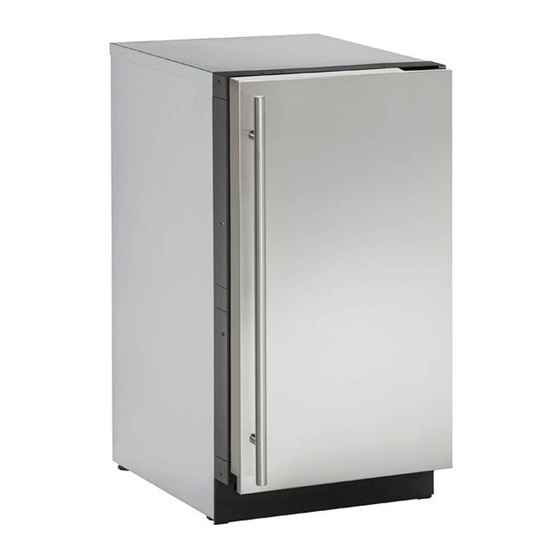
- Page 1 USER GUIDE & SERVICE MANUAL SAFETY • INSTALLATION & INTEGRATION • OPERATING INSTRUCTIONS • MAINTENANCE • SERVICE RIGHT PRODUCT. RIGHT PLACE. RIGHT TEMPERATURE. SINCE 1962. Modular 3000 Series 3018CLR 18" Clear Ice Machine • •...
-
Page 2: Table Of Contents
USER GUIDE u-line.com SAFETY • INSTALLATION & INTEGRATION • OPERATING INSTRUCTIONS • MAINTENANCE • SERVICE Contents Intro Cleaning Condenser Extended Non-Use Safety Safety and Warning Service Disposal and Recycling Troubleshooting Warranty Installation Environmental Requirements Service Extended Electrical Wire Diagram Cutout Dimensions... - Page 3 1. U-Line Customer Care must be contacted immediately at +1.800.779.2547. 2. Service or repairs performed on the unit without prior written approval from U-Line is not permitted. If the unit has been altered or repaired in the field without prior written approval from U-Line, claims will not be eligible.
-
Page 4: Safety And Warning
USER GUIDE u-line.com SAFETY • INSTALLATION & INTEGRATION • OPERATING INSTRUCTIONS • MAINTENANCE • SERVICE Safety and Warning NOTICE Please read all instructions before installing, operating, or servicing the appliance. Use this appliance for its intended purpose only and follow... -
Page 5: Disposal And Recycling
USER GUIDE u-line.com SAFETY • INSTALLATION & INTEGRATION • OPERATING INSTRUCTIONS • MAINTENANCE • SERVICE Disposal and Recycling DANGER RISK OF CHILD ENTRAPMENT. Before you throw away your old refrigerator or freezer, take off the doors and leave shelves in place so children may not easily climb inside. -
Page 6: Environmental Requirements
USER GUIDE u-line.com SAFETY • INSTALLATION & INTEGRATION • OPERATING INSTRUCTIONS • MAINTENANCE • SERVICE Environmental Requirements This model is intended for indoor/interior applications only and is not to be used in installations that are open/ exposed to natural elements. -
Page 7: Electrical
USER GUIDE u-line.com SAFETY • INSTALLATION & INTEGRATION • OPERATING INSTRUCTIONS • MAINTENANCE • SERVICE Electrical WARNING SHOCK HAZARD — Electrical Grounding Required. Never attempt to repair or perform maintenance on the unit until the electricity has been disconnected. Never remove the round grounding prong from the plug and never use a two-prong grounding adapter. -
Page 8: Cutout Dimensions
SAFETY • INSTALLATION & INTEGRATION • OPERATING INSTRUCTIONS • MAINTENANCE • SERVICE Cutout Dimensions CUTOUT DIMENSIONS PREPARE SITE Your U-Line product has been designed exclusively for a built-in installation. When built-in, your unit does not Preferred location for drain, water require additional air space for top, sides, or rear. -
Page 9: Product Dimensions
USER GUIDE u-line.com SAFETY • INSTALLATION & INTEGRATION • OPERATING INSTRUCTIONS • MAINTENANCE • SERVICE Product Dimensions 17-3/4" Not Including Handle (450 mm) 24" (610 mm) 33-11/16" to 34-11/16" (856 mm to 881 mm) 3-5/8" to 4-5/8" (92 mm to 118 mm) -
Page 10: Side By Side Installation
USER GUIDE u-line.com SAFETY • INSTALLATION & INTEGRATION • OPERATING INSTRUCTIONS • MAINTENANCE • SERVICE Side-by-Side Installation Hinge-by-Hinge Installation (Mullion) When installing two units hinge-by-hinge, 13/16" (22 mm) OTHER SITE REQUIREMENTS is required for integrated models. Additional space may be Side-by-Side Installation needed for any knobs, pulls or handles installed. -
Page 11: Water Hookup
USER GUIDE u-line.com SAFETY • INSTALLATION & INTEGRATION • OPERATING INSTRUCTIONS • MAINTENANCE • SERVICE Water Hookup CAUTION PREPARE PLUMBING Do not use any plastic water supply line. The line The water valve uses a standard 1/4" (6.35 mm) is under pressure at all times. Plastic may crack compression fitting. - Page 12 USER GUIDE u-line.com SAFETY • INSTALLATION & INTEGRATION • OPERATING INSTRUCTIONS • MAINTENANCE • SERVICE 3. Locate water 8. Install retaining clip. valve in the front of the unit and thread water supply line through. NOTICE Route the water supply line...
-
Page 13: Drain
DRAIN CONNECTION CAUTION With Trap and Vent Proper Drain If your U-Line unit did not come with a factory installed drain pump you must use a gravity A gravity drain may be used if: style drain connection. For assistance in Drain line has at least a 1"... - Page 14 (Optional Hook-Up) requirements for a gravity drain, you may have ordered a pre-installed U-Line P60 drain pump. Waste If you need to install a P60 drain pump into your unit, see Valve DRAIN PUMP section in the User Manual.
-
Page 15: Drain Pump
Ice Machine ships with before installing the unit. discharge tube installed.) • The U-Line P60-00 drain pump is designed to be used 5. 2x Vent tube Zip Ties exclusively on the U-Line Clear Ice Machine and is UL recognized only for use on the U-Line Clear Ice 6. - Page 16 USER GUIDE u-line.com SAFETY • INSTALLATION & INTEGRATION • OPERATING INSTRUCTIONS • MAINTENANCE • SERVICE Wiring Plug Ground Terminal Note: Slide clamp on hose end before installing hose. Do Discharge Tube Connector not tighten clamp until pump and hoses have been...
- Page 17 USER GUIDE u-line.com SAFETY • INSTALLATION & INTEGRATION • OPERATING INSTRUCTIONS • MAINTENANCE • SERVICE 8. Route the vent tube up CAUTION the back of the unit, next to the insulated tubes. When working with tools inside of unit, be...
-
Page 18: Anti-Tip Bracket
USER GUIDE u-line.com SAFETY • INSTALLATION & INTEGRATION • OPERATING INSTRUCTIONS • MAINTENANCE • SERVICE Anti-Tip Bracket SIDE MOUNT Left Hinged Cabinet Right Hinged Cabinet CAUTION The anti-tip bracket must be installed to prevent the unit from tipping when doors are fully opened or excess weight is placed on the front of the unit. -
Page 19: General Installation
USER GUIDE u-line.com SAFETY • INSTALLATION & INTEGRATION • OPERATING INSTRUCTIONS • MAINTENANCE • SERVICE General Installation INSTALLATION 1. Plug in the power/electrical cord. 1. Use a level to confirm the unit is level. Level 2. Gently push the unit into position. Be careful not to should be placed along entangle the cord or water and drain lines. -
Page 20: Integrated Grille / Plinth Dimensions
3. Apply double sided tape to the backside of the integrated grill (plinth strip/base fascia). Use the diagram below for reference. U-Line recommends ™ ™ tape, a high strength bonding tape. -
Page 21: Grille / Plinth Installation
USER GUIDE u-line.com SAFETY • INSTALLATION & INTEGRATION • OPERATING INSTRUCTIONS • MAINTENANCE • SERVICE Grille - Plinth Installation Installing the grille (plinth strip/base fascia) REMOVING AND INSTALLING GRILLE 1. Align slots in grille (plinth strip/base fascia) rail with (PLINTH STRIP/BASE FASCIA) -
Page 22: Door Stop
3. Once cover is removed, slide hinge pin into hole as shown. Pin should slide into place, stopping the door at Your U-Line unit was shipped to you with the optional 90° 90°; if the pin does not go into the hole shown, hold pin. -
Page 23: Door Adjust
USER GUIDE u-line.com SAFETY • INSTALLATION & INTEGRATION • OPERATING INSTRUCTIONS • MAINTENANCE • SERVICE Door Adjustments DOOR ALIGNMENT AND ADJUSTMENT Align and adjust the door if it is not level or is not sealing properly. If the door is not sealed, the unit may not cool... - Page 24 USER GUIDE u-line.com SAFETY • INSTALLATION & INTEGRATION • OPERATING INSTRUCTIONS • MAINTENANCE • SERVICE 3. Using T-25 Torx bit loosen screw #1 and remove screw #2 on top and bottom hinge. Slide and remove the door from unit. Completely remove screw #1 on top and bottom.
-
Page 25: First Use
USER GUIDE u-line.com SAFETY • INSTALLATION & INTEGRATION • OPERATING INSTRUCTIONS • MAINTENANCE • SERVICE First Use All U-Line controls are preset at the factory. Initial startup requires no adjustments. NOTICE U-Line recommends discarding the ice produced during the first two to three hours of operation to avoid possible dirt or scale that may dislodge from the water line. -
Page 26: Control Operation
Select CUSTOMER MENU The 3000 Series of U-Line undercounter refrigeration appliances contains a feature rich customer menu. The Customer Menu allows access to a series of advanced Power features including Energy Saver Mode, Sabbath Mode,... - Page 27 USER GUIDE u-line.com SAFETY • INSTALLATION & INTEGRATION • OPERATING INSTRUCTIONS • MAINTENANCE • SERVICE 3000 Series - Customer Menu Energy Saver Mode Energy Saver Mode Select Select Indicator WELCOME TO THE CUSTOMER MENU. USE ICE PRODUCTION UP/DOWN ARROWS TO (12m remaining) SCROLL SETTINGS.
- Page 28 RETURN TO MENU LANGUAGES ENGLISH 4. Press to confirm your choice. Down The U-Line 3000 Series of models supports a number of Fahrenheit / Celsius display languages including English, Spanish, French, Select German and Italian. RETURN TO MENU FARENHEIT/CELSIUS 1.
- Page 29 USER GUIDE u-line.com SAFETY • INSTALLATION & INTEGRATION • OPERATING INSTRUCTIONS • MAINTENANCE • SERVICE Clean Cycle To activate Silent Mode: 1. Press to select “Silence?”. Select RETURN TO MENU CLEAN CYCLE 2. Press . Silent Mode will now begin.
- Page 30 USER GUIDE u-line.com SAFETY • INSTALLATION & INTEGRATION • OPERATING INSTRUCTIONS • MAINTENANCE • SERVICE Help Select RETURN TO MENU Help Model 3018CLR 1-800-779-2547 Down To access the Help Menu, select “Help” from the Customer Menu. Press to scroll through available information.
-
Page 31: Ice
USER GUIDE u-line.com SAFETY • INSTALLATION & INTEGRATION • OPERATING INSTRUCTIONS • MAINTENANCE • SERVICE Your clear ice machine is pre-set to produce ice between the optimal dimensions illustrated below: ICE CUBE THICKNESS ADJUSTMENT Cube Details 1/4" TO 1/2" 1/16" TO 1/8"... - Page 32 USER GUIDE u-line.com SAFETY • INSTALLATION & INTEGRATION • OPERATING INSTRUCTIONS • MAINTENANCE • SERVICE ICE ADJUST Select RETURN TO MENU ICE ADJUST ICE ADJUST = 0 Down Adjust ice thickness as follows: 1. Press and hold for 5 seconds to enter the Customer Menu.
-
Page 33: Sabbath Mode
Sabbath Mode Select Down U-Line Clear Ice Machine models are Star-K certified and can be used during the Sabbath. View a full list of Star-K certified U-Line units at www.star-k.org. To prepare the unit for the Sabbath: 1. Press and hold the until the unit turns off. -
Page 34: Airflow And Product Loading
USER GUIDE u-line.com SAFETY • INSTALLATION & INTEGRATION • OPERATING INSTRUCTIONS • MAINTENANCE • SERVICE Airflow and Product Loading NOTICE The unit requires proper airflow to perform at its highest efficiency. Do not block the front grille at any time, or the unit will not perform as expected. -
Page 35: Maintenance
USER GUIDE u-line.com SAFETY • INSTALLATION & INTEGRATION • OPERATING INSTRUCTIONS • • SERVICE MAINTENANCE Cleaning Integrated Models To clean integrated panels, use household cleaner per the EXTERIOR CLEANING cabinet manufacturer’s recommendations. Stainless Models Stainless door panels and handles can discolor when... - Page 36 Standpipe Water trough U-Line Ice Machine Cleaner is used to remove lime scale 6. Clean the Interior Bin as follows: and other mineral deposits. Refer to the following steps to initiate the self-cleaning cycle.
- Page 37 Due to variations in water quality or inadequate maintenance your unit may become excessively coated in lime scale or calcium. U-Line offers a cost effective refresh kit which replaces many interior components and will return your unit to like new condition. Refresh kits may be ordered from your local distributor and installed by your local service company.
-
Page 38: Cleaning Condenser
USER GUIDE u-line.com SAFETY • INSTALLATION & INTEGRATION • OPERATING INSTRUCTIONS • MAINTENANCE • SERVICE Cleaning Condenser INTERVAL - EVERY SIX MONTHS To maintain operational efficiency, keep the front grille (plinth strip/base fascia) free of dust and lint, and clean the condenser when necessary. -
Page 39: Extended Non-Use
SAFETY • INSTALLATION & INTEGRATION • OPERATING INSTRUCTIONS • MAINTENANCE • SERVICE Extended Non-Use VACATION/HOLIDAY, PROLONGED SHUTDOWN For questions regarding winterization, please call U-Line at +1.800.779.2547. The following steps are recommended for periods of extended non-use: CAUTION 1. Remove all consumable content from the unit. -
Page 40: Troubleshooting
• Compressor: The compressor makes a hum or pulsing sound that may be heard when it operates. BEFORE CALLING FOR SERVICE If you think your U-Line product is malfunctioning, read • Evaporator: Refrigerant flowing through an evaporator the CONTROL OPERATION section to clearly understand may sound like boiling liquid. - Page 41 USER GUIDE u-line.com SAFETY • INSTALLATION & INTEGRATION • OPERATING INSTRUCTIONS • MAINTENANCE • SERVICE Problem Possible Cause and Remedy No Ice Ensure water is being supplied to the unit. Production Verify the ice making unit is turned on. Not Enough Ice Ensure the condenser coil is clean and free of any dirt or lint buildup.
-
Page 42: Warranty 1
One Year Limited Warranty For one year from the date of original purchase, this U-Line product warranty covers all parts and labor to repair or replace any part of the product that proves to be defective in materials or workmanship. For products installed and used for normal residential use, material cosmetic defects are included in this warranty, with coverage limited to 60 days from the date of original purchase. -
Page 43: Wire Diagram
USER GUIDE u-line.com SAFETY • INSTALLATION & INTEGRATION • OPERATING INSTRUCTIONS • MAINTENANCE • SERVICE Wire Diagram Wire Diagram 1... -
Page 44: Product Liability
The part that caused the damage must be returned to U-Line in its entirety. The part must be clearly labeled with the serial number of the unit it was removed from, the date, and the servicer who removed the part. -
Page 45: Warranty Claims
USER GUIDE u-line.com SAFETY • INSTALLATION & INTEGRATION • OPERATING INSTRUCTIONS • MAINTENANCE • SERVICE Warranty Claims warranty status. We also accept the following information to verify warranty status: The following information defines the parameters for filing a warranty claim: •... -
Page 46: Parts
Parts U-3018CLRS-00B Item Description U-Line P/N Anti tip brackets w/screws 80-54012-00 Back panel 80-54142-00 Circulation pump 80-54137-00 Cleaner 80-54081-00 Compressor electricals only 80-54140-00 Compressor w/electricals 80-54141-00 Condenser 80-54079-00 Condenser fan 80-54138-00 Condenser fan blade 80-54066-00 10 Cover pump, black 80-54073-00... -
Page 47: Ordering Replacement Parts
Warranty parts will be shipped at no charge after U-Line confirms warranty status. Please provide the model, serial number, part number and part description. Some parts will require color or voltage information. -
Page 48: System Diagnosis Guide
USER GUIDE u-line.com SAFETY • INSTALLATION & INTEGRATION • OPERATING INSTRUCTIONS • MAINTENANCE • SERVICE System Diagnosis Guide REFRIGERATION SYSTEM DIAGNOSIS GUIDE System Suction Suction Compressor Condenser Capillary Evaporator Wattage Condition Pressure Line Discharge Tube Normal Normal Slightly below Very hot... -
Page 49: Compressor Specifications
USER GUIDE u-line.com SAFETY • INSTALLATION & INTEGRATION • OPERATING INSTRUCTIONS • MAINTENANCE • SERVICE Compressor Specifications DANGER OVERLOAD PROTECTOR Electrocution can cause death or serious injury. Burns from hot or cold surfaces can cause serious injury. Take precautions when servicing this unit. -
Page 50: Troubleshooting Extended
DC outputs located on the relay/power board. Included in this section is some diagnostic tips and as always, if additional help is required please contact the U-Line Corp, “Customer Care Facility” at +1.800.779.2547 for assistance. NORMAL OPERATING SOUNDS All models incorporate rigid foam insulated cabinets to provide high thermal efficiency and maximum sound reduction for its internal working components. -
Page 51: Thermistor
Go to component testing and turn off fill valve, level unit if needed. Low Ice Production Dirty evaporator, dirty condenser, faulty bin Clean the evaporator using U-Line cleaner, clean the condenser coil if thermistor needed, check bin thermistor reading in service mode. Ice Does Not Fall... - Page 52 USER GUIDE u-line.com SAFETY • INSTALLATION & INTEGRATION • OPERATING INSTRUCTIONS • MAINTENANCE • SERVICE MAIN CONTROL The main control board is very robust and is rarely the cause of system issues. It is important to fully diagnose the board for any suspected failures before attempting to remove the board for replacement or service.
- Page 53 USER GUIDE u-line.com SAFETY • INSTALLATION & INTEGRATION • OPERATING INSTRUCTIONS • MAINTENANCE • SERVICE Control Operation - Service TO ENTER THE MAIN SERVICE MENU TO GO TO NEXT SUB-MENU ITEM YOU MUST ARROW UP TO “RETURN TO MENU” PRESS AND HOLD...
- Page 54 USER GUIDE u-line.com SAFETY • INSTALLATION & INTEGRATION • OPERATING INSTRUCTIONS • MAINTENANCE • SERVICE SERVICE MENU The All Errors option keeps record of any system errors. When an error occurs it is recorded to all errors. The In addition to a feature rich customer menu, the 3000...
- Page 55 USER GUIDE u-line.com SAFETY • INSTALLATION & INTEGRATION • OPERATING INSTRUCTIONS • MAINTENANCE • SERVICE To access All Errors follow the steps below. 1. Use to select “Relay Status”. 1. Press to select “All Errors”. 2. Press 2. Press 3. Press to scroll through available information.
- Page 56 USER GUIDE u-line.com SAFETY • INSTALLATION & INTEGRATION • OPERATING INSTRUCTIONS • MAINTENANCE • SERVICE Relay Toggle Input Status Select Select RETURN TO MENU RETURN TO MENU RELAY TOGGLE INPUT STATUS MULL OFF DOOR OPEN COND OFF IN2 OPEN Down...
- Page 57 USER GUIDE u-line.com SAFETY • INSTALLATION & INTEGRATION • OPERATING INSTRUCTIONS • MAINTENANCE • SERVICE To access Outputs To change offsets 1. Press to select “Outputs”. 4. Press , the selected thermistor will begin to flash. 2. Press 5. Press to modify offset value.
- Page 58 USER GUIDE u-line.com SAFETY • INSTALLATION & INTEGRATION • OPERATING INSTRUCTIONS • MAINTENANCE • SERVICE Differentials Evap Fan (Not Used) Select Select RETURN TO MENU RETURN TO MENU EVAP FAN DIFFERENTIALS EVAP FAN ON = 1 ZONE = 1°F EVAP FAN OFF = 60...
- Page 59 OFF. Down 1. Press to select “Factory Wi Fi”. NOTICE Before altering model selection U-Line customer 2. Press service must be notified. Failure to notify customer service will result in voiding of the manufacturer warranty. 3. Press select “OFF”.
- Page 60 USER GUIDE u-line.com SAFETY • INSTALLATION & INTEGRATION • OPERATING INSTRUCTIONS • MAINTENANCE • SERVICE Fan Delay Showroom Mode Select Select RETURN TO MENU RETURN TO MENU FAN DELAY SHOWROOM MODE FAN DELAY ON = 1 FAN DELAY OFF = 2...
- Page 61 USER GUIDE u-line.com SAFETY • INSTALLATION & INTEGRATION • OPERATING INSTRUCTIONS • MAINTENANCE • SERVICE Thermistors The Ice Bin and Ambient Thermistors are both type 1 thermistors. If a thermistor is suspected of being defective Thermistors are used for various temperature readings.
- Page 62 USER GUIDE u-line.com SAFETY • INSTALLATION & INTEGRATION • OPERATING INSTRUCTIONS • MAINTENANCE • SERVICE The Condensor Line Out Thermistor is a type 2 thermistor. At 77° the resistance should read 10k OHMs +/-5%. Thermistor Resistance Data - Type 2...
-
Page 63: Defrost
USER GUIDE u-line.com SAFETY • INSTALLATION & INTEGRATION • OPERATING INSTRUCTIONS • MAINTENANCE • SERVICE Defrost These models have no defrost options. Defrost 1...
Need help?
Do you have a question about the U-3018CLR and is the answer not in the manual?
Questions and answers