Advertisement
Quick Links
Knobs
Clip Launch Buttons
Faders
Inputs / Outputs
Power
Dimensions
(width x depth x height; no cable)
Weight
(no cable)
T e c h n i c a l S p e c i f i c a t i o n
T e c h n i c a l S p e c i f i c a t i o n
T e c h n i c a l S p e c i f i c a t i o n
T e c h n i c a l S p e c i f i c a t i o n
SERVICE MANUAL
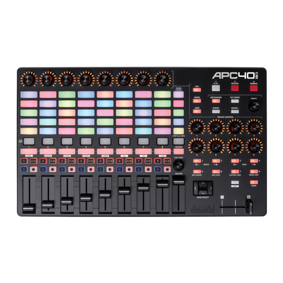
SPECIFICATIONS
8 360° track pan/send/assignable knobs
8 360° device control knobs
1 360° cue level knob
1 360° tempo knob
40 backlit RGB buttons in a 8x5 matrix
5 scene launch buttons
8 45mm track volume faders
1 45mm master volume fader
1 45mm crossfader
1 USB port
1 1/4" (6.35mm) TS jack for footswitch input
USB-bus-powered
16.7" x 10.0" x 1.8"
42.4 cm x 25.4 cm x 4.6 cm
3.97 lbs.
1.8 kg
MODEL:APC40MKII
Advertisement

Related Manuals for Akai APC40MKII


Summary of Contents for Akai APC40MKII
- Page 1 SERVICE MANUAL MODEL:APC40MKII SPECIFICATIONS 8 360° track pan/send/assignable knobs 8 360° device control knobs Knobs 1 360° cue level knob 1 360° tempo knob 40 backlit RGB buttons in a 8x5 matrix Clip Launch Buttons 5 scene launch buttons 8 45mm track volume faders...
-
Page 2: Disassembly Procedures
DISASSEMBLY PROCEDURES 1. DISASSEMBLE THE BOTTOM PANEL. (Fig.1) (A) REMOVE 14 SCREWS FROM BOTTOM PANEL. (Fig.1) 2. DISASSEMBLE THE MAIN PCB ASS’Y. (Fig.2) (A) REMOVE 3 SCREWS FROM THE MAIN PCB ASS’Y. (B) REMOVE 2 CABLES. (Fig.2) - Page 3 3.DISASSEMBLE THE TOP PANEL AND TOP PCB ASS’Y .(Fig.3) (A) REMOVE 18 KNOBS AND 10 FADERS. (B) REMOVE 18 NUTS AND 18 WASHERS. (C) REMOVE 12 SCREWS. (D) REMOVE 2 CABLES. (Fig.3)
-
Page 4: Wiring Diagram
WIRING DIAGRAM (US/AUS) SEQUENCE NO OF EXPLODE DIAGRAM WILL BE MARKED ON REF. COLUMN OF BOM LIST... -
Page 5: Packing Diagram
PACKING DIAGRAM (US) - Page 6 PACKING DIAGRAM (AUS)
-
Page 7: Explode Diagram
EXPLODE DIAGRAM (US/AUS) - Page 8 ADA5AKA01 DESCRIPTION LEVEL ADA5AKA01 ADA5 USB POWER USA BASJ5012B PU Stand CA040210002 USB Cable FFC4005001001 FFC 40pin pitch 0.5mm Length 100mm LAC22AKA339 Stick S/N Ableton LAC22AKA340 Stick S/N Puremagnetik LAC67YAH261 Label φ8mm Green LAP67YAH255 Sticker φ10mm red NM1504403 FELT-45-ADHESIVE PADA5AKA01 Packing Assembly AL7-51-0226-M Safety Manual...
- Page 9 AL2-51-4401 Transistor 2N4401 NPN SOT-23 (Transistor Q2,3,5 MMBT4401LT1 NPN SOT-23) AL2-51-4403 Transistor 2N4403 PNP SOT-23 AL2-52-5242 Diode MMBZ5242B AL2-54-6306 Mosfet FDC6306P P-CH SSOT-6 AL2-61-7223 IC NJU7223DL1-33 3.3V TO-252 AL4-08-0402 Con USB 4-Pin Female PC-MNT Horizontal AL6-02-0001 Switch Push 2P2T Dual Row Lock CS102K5003X7R CCAP SMD 1nF/50V 10% 0603 X7R C3,9,11,12,15,17...
- Page 10 ECS10710D Capacitor Electrolytic 100UF 10V SMD-D C19~21 FCN1T0504001 FCN Down Touch ZIF SMD Pitch=0.5mm 40 J1,2 IC74AHC541PW IC 74AHC541PW Octal Buffer/Line driver 3-state output TSSOP-20 ICSN74LV595APWR IC 74LV595A 8-bit SERIAL SHIFT W/LATCHES U4,9~15,22,24,37,42,48,60~64 TRI-STATE TSSOP-16 ICYH102M02 IC(AL2-80-0256+Program)TQFP-100 AL2-80-0256 IC LCMX0256 TQFP-100 (U3) LDJ1M1F1BB7R4S3 Liquid-emitting Diode Red/Green/Blue SMD...
- Page 11 ADA5 – Test Procedure 1. Open ADA5-Testapp.exe 2. Select APC40 mkII from the MIDI Device list for both Input and Output 3. Connect a footswitch into the FS1 input on the device. 4. Press the ‘Reset’ button. 5. Verify Firmware Version is the latest MP approved firmware. 6.
- Page 12 2. You will see the corresponding button on screen change from red to green if the button has been verified to be working properly. 3. You will also see the LED under the button light. In the case of Play, Record and Session, the LED is above the knob.
- Page 14 SW-DRV[0..7]...
Need help?
Do you have a question about the APC40MKII and is the answer not in the manual?
Questions and answers