CIAT COADIS LINE 600 Instruction Manual
Hide thumbs
Also See for COADIS LINE 600:
- Instruction manual (140 pages) ,
- Instruction manual (158 pages)
Table of Contents
Advertisement
Quick Links
Advertisement
Table of Contents

Related Manuals for CIAT COADIS LINE 600


Summary of Contents for CIAT COADIS LINE 600
- Page 1 EN7521261-02 05 - 2022 I n s t r u c t i o n m a n u a l...
- Page 2 +50°C 35kg -10°C COADIS LINE...
- Page 3 Fig. 1 COADIS LINE...
- Page 4 Fig. 2 Ref. produit/Item Ref. Designation/Description 7405791.344701 CDL 634T PMS An/Year N° série/Serial Nbr Composants/Components Repère/Part 2014 02230837/00001 Moteur/Motor (Ph/Hz/V) Batterie/Hydro. coil Fluide/Fluid 1+N 50/60HZ 230V+T P. moteur/Motor P. (W) Elec Element (Ph/Hz/V) Maxi pressure 1+N50HZ/60HZ 230V 1600000 PA (16BAR) I.
- Page 5 Fig. 4 Préconisé* 600mm 300 mini. Visual 180° Visual 360° Recommended COADIS LINE...
- Page 6 Fig. 5 ~ 45° COADIS LINE...
- Page 7 Fig. 6 Fig. 7 131,5 18,5 Fig. 8 COADIS LINE...
- Page 8 Fig. 9 Fig. 10 230/1/50 230/1/50 PE PE Ph Ph Ph N PE PE Ph Ph Ph N Nota Vert/Jaune / Green/Yellow LS MS HS N 0-10V BOITIER H.E.E Vert/Jaune / Green/Yellow COADIS LINE VIII...
- Page 9 Fig. 11 230/1/50 230/1/50 PE PE Ph Ph Ph N PE PE Ph Ph Ph N Nota Vert/Jaune / Green/Yellow LS MS HS N 0-10V BOITIER H.E.E Vert/Jaune / Green/Yellow 230/1/50 230/1/50 Fig. 12 PE PE Ph Ph Ph N PE PE Ph Ph Ph N...
- Page 10 Fig. 13 Fig. 14 Fig. 15 Fig. 16 Fig. 17 COADIS LINE...
- Page 11 Fig. 18 COADIS LINE...
- Page 12 Fig.19 Fig.20 Fig.21 COADIS LINE...
-
Page 13: Table Of Contents
CONTENTS 1 - UNPACKING THE UNIT, CHECKING AND STORING ...................14 2 - HANDLING ..............................15 3 - DESCRIPTION OF THE UNIT (FIG. 1) ......................16 3.1 - Data plate (Fig. 2)............................16 4 - INSTALLATION AND CONNECTIONS ......................17 4.1 - Mechanical connections ..........................17 4.2 - Air connections ............................17 4.3 - Hydraulic connections ..........................18 4.4 - Condensate pan draining connection ......................21... -
Page 14: Unpacking The Unit, Checking And Storing
1 - UNPACKING THE UNIT, CHECKING AND STORING Thank you for purchasing a CIAT unit. We trust that this unit will give you complete satisfaction. To ensure correct operation, all connections (electrical, hydraulic, etc.) must be made in accordance with industry practice and the regulations in force in the country of use. -
Page 15: Handling
2 - HANDLING For your safety, wear protective gloves! The unit must be handled with care and preferably laid flat. Impacts may cause damage to the frame or the body of the unit and adversely affect its main functions and its appearance. The unit should preferably be lifted using the brackets. -
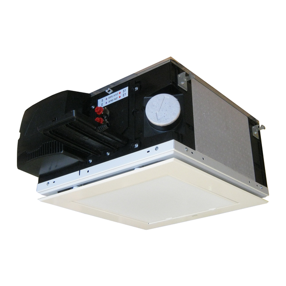
Page 16: Description Of The Unit (Fig. 1)
3 - DESCRIPTION OF THE UNIT (FIG. 1) The COADIS LINE™ (CDL) unit that you have just purchased is part of a range of comfort units designed for integration into a suspended ceiling. It is used for heating, cooling, dehumidification and air filtration. It includes a coil with one or two hot water or cold water supply circuits and may include an electrical heater for heating. -
Page 17: Installation And Connections
CIAT strongly recommends the use of antivibration resilient mounts when securing the unit, in order to reduce the transmission of vibrations through the building structure during operation. -
Page 18: Hydraulic Connections
The coils are equipped with a header coupling with flat face swivel nuts with a female thread, diameter G½˝ and an O-ring. (Supplied by CIAT) . The header coupling is equipped with an air bleed valve (Fig. 8 - a) at the high point with partial draining at the low points (Fig. - Page 19 Use two wrenches, one to hold and the other to tighten to ensure a tight seal. Always fit the valve in the right direction. On the 2 CIAT couplings, the direction of flow should be A → AB (A being connected to the coil and AB to the hydraulic network).
- Page 20 4 - INSTALLATION AND CONNECTIONS ■ Opening the thermo valve: There are two options: 1) Remove the servomotor and fit the cap, which will cause pressure to be applied to the shaft, thereby opening the valve. 2) Request that the control valve opens via the controller. ■...
-
Page 21: Condensate Pan Draining Connection
50°C. This is especially important for units installed in confined spaces (e.g. in suspended ceilings). CIAT shall not be liable for damage to valves caused by faulty design of the hydraulic supply network or incorrect commissioning. -
Page 22: Electrical Connections
4 - INSTALLATION AND CONNECTIONS Table of actual flow rates for the DE05UCC pump with Ø 6 mm PVC internal pipe: TABLE OF ACTUAL FLOW RATES (l/h) Total pipe length (internal Ø, 6 mm) Discharge height 10 m 20 m 30 m 10,4 Under operating conditions outside the recommended temperature and relative humidity range (page EN-2), the... - Page 23 Note: if necessary, the output of the 300W electric heater can be reduced by removing the shunt positioned between terminals 8 and 9. CIAT recommends using a system that controls the unit in relation to the temperature of the water (to actuate the valve(s) and the use of an electric heater.
- Page 24 • Switch on the unit and select the ventilation speed to be modified using the thermostat. • Use the "CIAT speed control unit" accessory supplied as an option to adjust each speed (rpm) in accordance with the instructions included with the unit.
- Page 25 4 - INSTALLATION AND CONNECTIONS Connection Connect the electrical connections to the connectors as per the wiring diagram below, and lock the wires using the special cable grommets. Power cable Max Ø 12 Connect the earth before making any other connections. Check that the stripped section of the GREEN/YELLOW cable is longer than the others.
-
Page 26: Servicing And Maintenance
CIAT recommends regular inspections of the filter's appearance in order to define the frequency with which it should be replaced, which varies depending on the premises and the operating conditions (replacement at least every two years). -
Page 27: Fan Motor Assembly
5 - SERVICING AND MAINTENANCE 5.3 - Fan motor assembly From time to time, check that the turbines and the motor are clean. If necessary, clean them using a vacuum cleaner, taking care to ensure they are not damaged. The electric motor's bearings are lubricated for life and do not require specific maintenance. Removing the fan motor assembly: ■... -
Page 28: Ce Certificate Of Conformity
6 - CE CERTIFICATE OF CONFORMITY Declaration of Conformity UE This unit complies with the provisions of European Directives: ■ 2006/42/EC (Machinery) ■ 2014/30/EU (EMC) ■ 2011/65/EU (RoHS) ■ 2009/125/EC (Eco Design) and regulation 327/2011/EU ■ REGULATION (EC) No 1907/2006 (REACH) UK Declaration of Conformity This unit complies with the requirements of: ■... -
Page 29: Testing & Warranty
All our units are tested and proven before leaving the factory. They are guaranteed against all manufacturing defects. CIAT shall not be held liable for any type of corrosion. CIAT's warranty does not cover damage resulting from incorrect electrical wiring, inadequate electrical or thermal protection or failure to use a filter. -
Page 30: Safety Considerations Relating To Final Shut-Down
8 - SAFETY CONSIDERATIONS RELATING TO FINAL SHUT-DOWN Separate the units from their energy sources, allow them to cool down and then drain completely. DISMANTLING Never work on a unit that is still powered on. Respect the local environmental laws and regulations. Presence of waste electrical and electronic equipment (WEEE): At the end of its life, units must be disassembled, with any contaminated fluids removed by professionals, and then processed via approved channels for waste electrical and electronic equipment (WEEE). - Page 32 Manufacturer: Carrier SCS, Rte de Thil - 01120 Montluel, France. Printed in the European Union. Manufacturer reserves the right to change any product specifications without notice.
Need help?
Do you have a question about the COADIS LINE 600 and is the answer not in the manual?
Questions and answers