Carefree MIRAGE MANUAL Service Manual
Hide thumbs
Also See for MIRAGE MANUAL:
- Service manual (34 pages) ,
- Installation manual (15 pages) ,
- Owner's manual (8 pages)
Table of Contents
Advertisement
Quick Links
RV
These instructions apply to all models listed. Details and procedures unique to a specific
T
C
ABLE OF
ONTENTS
Product Overview .......................................................................................................................... 1
Mirage Patio Awning Specifications........................................................................................................1
Canopy Replacement .................................................................................................................... 2
Spring Arm Replacement.............................................................................................................. 3
Replacing the Arm ..................................................................................................................................3
To Replace the Lead Rail Connector: .................................................................................................4
To Replace the Case Arm Support .....................................................................................................4
Motor Replacement ....................................................................................................................... 5
Hand Crank Replacement ............................................................................................................. 6
Diagnostics/Troubleshooting....................................................................................................... 7
Common Operation Items ...................................................................................................................7
System Tests ..........................................................................................................................................8
Standard Electronics w/ Optional Auto-Retract...................................................................................8
Direct Response w/ DKS Style Switch Panel......................................................................................8
Testing the Key FOB...........................................................................................................................9
Electrical ...................................................................................................................................... 14
Wiring Harness - Optional Light & Speaker End Caps ........................................................................15
Wiring Diagram - Direct Connect (No Relay Control Box) ....................................................................15
Wiring Diagram -Switches w/ Relay Control Box - Previous................................................................16
Wiring Diagram -Switches w/ Relay Control Box - Current..................................................................17
Wiring Diagram - Standard Electronics w/ Optional Auto Retract........................................................18
Wiring Diagram - Direct Response Electronics....................................................................................19
Wiring Diagram - Direct Response Winnebago ...................................................................................20
Control Board Replacement - Direct Response....................................................................................21
Sensor Replacement for Direct Response ...........................................................................................22
Installing the Vertical Mount Bracket.................................................................................................22
Installing a New Sensor ....................................................................................................................22
Optional Manual Bypass Switch - Direct Response.............................................................................23
Standard Service Procedures .................................................................................................... 24
Manual Override (motorized versions only) ..........................................................................................24
Adjusting the Pitch ................................................................................................................................24
Setting the Motor Limits ........................................................................................................................25
Adjusting the OUT Limit Switch.........................................................................................................25
Adjusting the IN Limit Switch.............................................................................................................25
Setting the Wind Speed Sensitivity (standard electronics) ...................................................................26
Programming the Remote (standard electronics w/ optional remote)...................................................26
Programming the Remote Receiver (Direct Response) .......................................................................27
Operational Notes: ............................................................................................................................27
Standard Maintenance ................................................................................................................ 28
Part Number Listing .................................................................................................................... 29
Part Number Configuration ...................................................................................................................29
Illustrated Parts List ..............................................................................................................................30
052979-301r5
S
TANDARD
model are labeled appropriately.
Printed in USA
S
ERVICE
M
ANUAL
/A
-R
/D
UTO
ETRACT
IRECT
M
ANUAL
M
IRAGE
/M
OTORIZED
R
ESPONSE
March, 2009
Advertisement
Table of Contents

Subscribe to Our Youtube Channel
Related Manuals for Carefree MIRAGE MANUAL


Summary of Contents for Carefree MIRAGE MANUAL
-
Page 1: Table Of Contents
ERVICE ANUAL IRAGE ANUAL OTORIZED TANDARD ETRACT IRECT ESPONSE These instructions apply to all models listed. Details and procedures unique to a specific model are labeled appropriately. ABLE OF ONTENTS Product Overview .......................... 1 Mirage Patio Awning Specifications......................1 Canopy Replacement ........................2 Spring Arm Replacement...................... - Page 2 ROPRIETARY TATEMENT The Mirage Patio Awning is a product of Carefree of Colorado, located in Broomfield, Colorado, USA. The information contained in or disclosed in this document is considered proprietary to Carefree of Colorado. Every effort has been made to ensure that the information presented in the document is accurate and complete.
-
Page 3: Product Overview
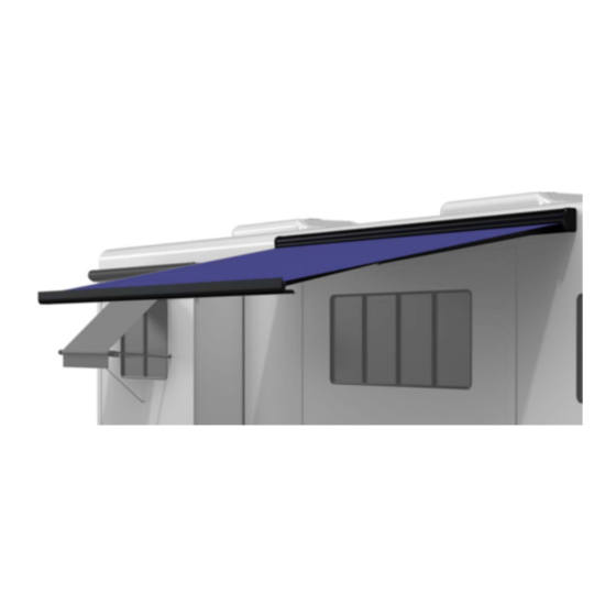
Carefree of Colorado Service Manual IRAGE RODUCT VERVIEW The Mirage Patio Awning offers the coach owner an awning system that provides as much or as little shade as required. The canopies are housed in an aluminum case that easily blends in with the coach side wall. -
Page 4: Canopy Replacement
Service Manual Carefree of Colorado IRAGE ANOPY EPLACEMENT During the following instructions, use the manual override procedure on page 24 to open and close the awning. Case End Plate Phillips Head Outer Spring Arms Screw Idler (ref) Rubber Well Canopy... -
Page 5: Spring Arm Replacement
Carefree of Colorado Service Manual IRAGE PRING EPLACEMENT CAUTION HE SPRING ARM IS UNDER TENSION TO OPEN SE EXTREME CARE TO FIRMLY HOLD THE SPRING ARMS DURING ASSEMBLY AND DISASSEMBLY TO AVOID ANY SUDDEN OR UNEXPECTED MOVEMENT BY THE ERIOUS PERSONAL INJURY AND... -
Page 6: To Replace The Lead Rail Connector
Service Manual Carefree of Colorado IRAGE 15. Lift the arm assembly into position. 16. (refer to Detail B) Slide the case arm knuckle into the support inside the case and secure with 1 each M12-1.25 x 25 bolt and washer and 1 each M12-1.25 x 40 bolt, washer and saddle. Do not tighten at this time. -
Page 7: Motor Replacement
Carefree of Colorado Service Manual IRAGE OTOR EPLACEMENT During the following instructions, use the manual override procedure on page 24 to open and close the awning. Phillips Head Outer Spring Arms Roll Bar (ref) Screw Drive Gear (ref) Rubber Well... -
Page 8: Hand Crank Replacement
Service Manual Carefree of Colorado IRAGE RANK EPLACEMENT NOTE: Replacement crank assemblies have a shorter extension shaft. The eyelet does not extend below the case. If replacing an original crank, it is also necessary to replace the crank handle (crank handle p/n R001564). -
Page 9: Diagnostics/Troubleshooting
Carefree of Colorado Service Manual IRAGE IAGNOSTICS ROUBLESHOOTING The following procedures are intended to aid the service technician to logically resolve operational issues with the Mirage installation. These procedures do not address conditions that may arise with the basic awning installation. -
Page 10: System Tests
Service Manual Carefree of Colorado IRAGE YSTEM ESTS Standard Electronics w/ Optional Auto-Retract 1. Provide 110VAC and 12DC power to the awning system. 2. At the switch panel, turn the to "ON". POWER SWITCH 3. Press the button to extend the awning. The awning will continue to the maximum extension. -
Page 11: Testing The Key Fob
Carefree of Colorado Service Manual IRAGE 1. While observing the control panel, have a second person initiate 110VAC power to the coach and awning system. The following should occur: 1.1 The Auto-Retract and Wind Speed LEDs should illuminate briefly then extinguish. - Page 12 Service Manual Carefree of Colorado IRAGE In the charts below, YES is a positive response to the test; NO is a negative response. WNING PERATE Confirm 110VAC power to control box. 1. Shut off power source. Power is present; go to test B 2.
- Page 13 Carefree of Colorado Service Manual IRAGE WNING PERATE (continued from previous page) Test Key pad (System #4 – Direct Response Only) Confirm 110VAC power to control box Power is present; go to test B 1.1 Shut off power source. Check vehicle circuits and fuses.
- Page 14 Service Manual Carefree of Colorado IRAGE WNING DOES NOT ETRACT IN TANDARD LECTRONICS NOTE: For standard electronics with the optional auto-retract anemometer; the auto-retract system is always on. Confirm that the sensitivity is set correctly (if set on highest level, system may appear not to function). Setting the sensitivity is in the Owner's manual and on page 26.
- Page 15 Carefree of Colorado Service Manual IRAGE EMOTE PERATE STANDARD LECTRONICS W PTIONAL EMOTE Confirm normal operation with switches If system does not operate, go to test Confirm batteries in remote are good. Pressing any Replace as needed button on the remote will illuminate the LED indicator on...
-
Page 16: Electrical
Service Manual Carefree of Colorado IRAGE LECTRICAL IMPORTANT NOTICES: Failure to follow the wiring instructions in this publication may void the motor warranty. All wiring must conform to NEC (National Electrical Code) and local codes. wire two or more motors to one switch—No parallel wiring. -
Page 17: Wiring Harness - Optional Light & Speaker End Caps
Carefree of Colorado Service Manual IRAGE – O & S IRING ARNESS PTIONAL IGHT PEAKER (THIS SYSTEM IS NO LONGER AVAILABLE) +12VDC Stereo Consult Stereo Manual for Speaker Connections Shielded Outdoor Speaker Grade Wire 16 AWG UL Listed Outdoor Grade Wire 16 AWG UL Listed... -
Page 18: Wiring Diagram -Switches W/ Relay Control Box - Previous
Service Manual Carefree of Colorado IRAGE –S IRING IAGRAM WITCHES W ELAY ONTROL REVIOUS SYSTEM #2 - The current configuration of this switch configuration has been updated to use R019468-006 switch kit. For switch replacement use R019468-006 kit and the wiring diagram on the next page. -
Page 19: Wiring Diagram -Switches W/ Relay Control Box - Current
Carefree of Colorado Service Manual IRAGE –S IRING IAGRAM WITCHES W ELAY ONTROL URRENT SYSTEM #2 +12VDC Extend/Retract Rear View of Switch On/Off Detail For LH Configuration Reverse Red & Black Wires on Terminals 4 & 5 12VDC Ground Black... -
Page 20: Wiring Diagram - Standard Electronics W/ Optional Auto Retract
Service Manual Carefree of Colorado IRAGE – S IRING IAGRAM TANDARD LECTRONICS W PTIONAL ETRACT SYSTEM #3 (THIS SYSTEM IS NO LONGER AVAILABLE) Green Green Black Black DOWN White White 3 Conductor From Motor +12VDC 14AWG NM Wire NEUT w/ Ground... -
Page 21: Wiring Diagram - Direct Response Electronics
Carefree of Colorado Service Manual IRAGE – D IRING IAGRAM IRECT ESPONSE LECTRONICS Ignition Switched +12VDC Receiver Awning #1 12VDC Ignition Ground Sensor Lockout Sensor (Optional) RH Motor Wire Shown Splitter See Detail A for LH Motor Remote Key Pad... -
Page 22: Wiring Diagram - Direct Response Winnebago
Service Manual Carefree of Colorado IRAGE – D IRING IAGRAM IRECT ESPONSE INNEBAGO Ignition Switched +12VDC 12VDC OEM Lockout Ground Harness Receiver Wires to Ignition Lockout are not pin specific Keypad Ignition Lockout Awning Sensor Sensor Splitter Coupler OEM Keypad... -
Page 23: Control Board Replacement - Direct Response
Carefree of Colorado Service Manual IRAGE ONTROL OARD EPLACEMENT IRECT ESPONSE When a control board fails, it is possible to replace the board. It is not necessary to replace the complete control box assembly. CAUTION HE PROCEDURE REQUIRES HANDLING THE PRINTED CIRCUIT BOARD... -
Page 24: Sensor Replacement For Direct Response
Service Manual Carefree of Colorado IRAGE ENSOR EPLACEMENT FOR IRECT ESPONSE NOTE: The original Direct Response Shake Sensor was mounted horizontally on the inside of the lead rail. For product integrity, sensors are now mounted vertically. If replacing an original horizontally mounted sensor, it is necessary to install the vertical mounting bracket for the replacement sensor. -
Page 25: Optional Manual Bypass Switch - Direct Response
Carefree of Colorado Service Manual IRAGE 4. Carefully remove the board from the case. In some instances, the board may be tacked with adhesive and must be pried out. Use care to not damage the cord or connector. 5. Disconnect the cable from the board and slip the connector out of the case. Set the old sensor parts out of the way. -
Page 26: Standard Service Procedures
Service Manual Carefree of Colorado IRAGE TANDARD ERVICE ROCEDURES ANUAL VERRIDE MOTORIZED VERSIONS ONLY If 110V power is not available to the coach, the Mirage awning Wall can still be safely retracted using the manual override. The bypass may be accessed from inside the case on the motor Remove Screw housing or from the top of the case above the motor housing. -
Page 27: Setting The Motor Limits
Carefree of Colorado Service Manual IRAGE ETTING THE OTOR IMITS The motor limit switches are preset at the factory for best operation of the awning. The “ ” limit switch is used to stop the motor when the awning is fully extended. The “... -
Page 28: Setting The Wind Speed Sensitivity (Standard Electronics)
Service Manual Carefree of Colorado IRAGE ETTING THE PEED ENSITIVITY STANDARD ELECTRONICS The wind sensitivity can be set for a preferred wind speed. 1. Open the control box. 2. In the center of the control board, locate the speed adjust switch. -
Page 29: Programming The Remote Receiver (Direct Response)
Carefree of Colorado Service Manual IRAGE ROGRAMMING THE EMOTE ECEIVER IRECT ESPONSE Early transmitters & receivers operate on a frequency of 418MHz. Models for 2007 & on operate on 433MHz. The transmitter and receiver frequencies must match. Identifying the transmitter frequency is described under the operational notes below. -
Page 30: Standard Maintenance
Service Manual Carefree of Colorado IRAGE TANDARD AINTENANCE Maintaining the Carefree Manual Patio Awning is easy. Just follow these basic steps: Always operate the awning according to the instructions. Periodically check that the fasteners are tight. Tighten if necessary. -
Page 31: Part Number Listing
Carefree of Colorado Service Manual IRAGE UMBER ISTING UMBER ONFIGURATION Example: Part Number: V W 1 9 C W 2 5 1 0 D R Mirage Box 19’ Toast (acrylic) White 10’ Direct Response Awning Extension TYLE CODE ANOPY OLOR... -
Page 32: Illustrated Parts List
Service Manual Carefree of Colorado IRAGE LLUSTRATED ARTS DISCONTINUED Detail Detail (Lighted Endcaps w/ Speakers) (Manual Configuration) 12 11 Simple Electrical Direct Response Electronics R E TR A C T O FF E X TE A w n in g C o n... - Page 33 Discontinued End Cap w/ Light and Speaker, Left Discontinued End Cap w/ Light and Speaker, Right 55WH3 Bulb (not shown) Not Available from Carefree R019468-006 Switch Kit (includes switches, base plate, bezel and screws) R060487-001 Relay Box Switch, SPST, Ext/Ret...
- Page 34 Service Manual Carefree of Colorado IRAGE Notes: 1. XXX = Color; xxx = Length in inches. 2. End Caps w/ Lights and Speakers have been discontinued and are no longer available. 3. Direct Response system is available as a factory option for the Mirage. Upgrade kits are available for Mirage (SR0035).
Need help?
Do you have a question about the MIRAGE MANUAL and is the answer not in the manual?
Questions and answers