Advertisement
Quick Links
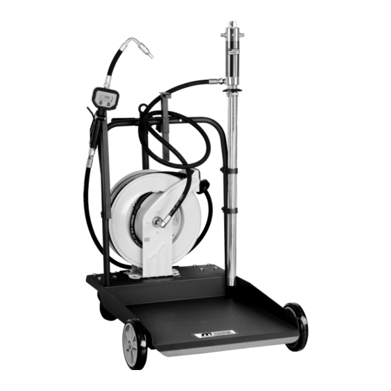
High Flow Mobile Oil Dispensing Kit
Instruction Manual
OKTR585-1-001
WARNING:
Read carefully and understand all INSTRUCTIONS before operating. Failure to follow the safety
rules and other basic safety precautions may result in serious personal injury.
Save these instructions in a safe place and on hand so that they can be read when required.
Keep these instructions to assist in future servicing.
REV 03/10/22
Advertisement

Related Manuals for Macnaught OKTR585-1-001


Summary of Contents for Macnaught OKTR585-1-001
- Page 1 High Flow Mobile Oil Dispensing Kit Instruction Manual OKTR585-1-001 WARNING: Read carefully and understand all INSTRUCTIONS before operating. Failure to follow the safety rules and other basic safety precautions may result in serious personal injury. Save these instructions in a safe place and on hand so that they can be read when required.
- Page 2 GENERAL SAFETY REGULATIONS WARNING: The warnings, cautions, and instructions discussed in this instruction manual cannot cover all possible conditions or situations that could occur. It must be understood by the operator that common sense and caution are factors that cannot be built into this product, but must be supplied by the operator.
- Page 3 1. Installation steps (Note: before connecting and assembling each component, please assemble each component according to the component instructions). Step 1 Step 2 1. Assemble trolley parts 1 according to 1. The hose reel 2 is fixed on the corresponding 1708003 trolley instructions.
- Page 4 3 years from date of purchase, but not including wearing parts. 2. Macnaught’s liability is limited to replacement or repair of defective material within the warranty period, when returned freight prepaid to the distributor or their designated service depot.
- Page 5 TECHNICAL DETAILS - TROLLEY ASSEMBLY Item No. Drums Weight Drums Diameter 1708003 600mm 180-220kgs EXPLODED AND PARTS LIST Part No. Description Q’ty Part No. Description Q’ty Accessories Axle Drum Holder Support Hexagon Bolt Handle Trolley Top Pump Support Joint Pin Hexagon Screw Set Handle Joint Stopper...
- Page 6 TECHNICAL DETAILS - OIL PUMP ASSEMBLY Item No. 1701056 Drum application 180-220L / 48-58gallon Pressure ratio Air inlet pressure 5-8bar / 70-115psi Max. fluid pressure 40bar / 580psi Air motor effective diameter 63mm / 2.5" Air consumption (per minute) @ 8bar / 180L / @ 115psi / 6.5CFM Max.free flow rate (per minute) 28L / 7.4gallon Suction tube diameter...
- Page 7 TROUBLE SHOOTING Problem Cause Solution The pump continues to operate 1. The is a oil leak at some point of 1. Check and tighten unions. Repair after the gun trigger has been the circuit. the leak. released. 2. Valve sets (part No.39, 40, 41) 2.
- Page 8 HOW TO USE Directly Fitted Pump into the Drum 1. Insert the suction tube of pump into the drum and secure with ring nut, suitable for commercial drums with 57 diameter hole and threading 2” BSP. 2. Fit a oil delivery tube for oil outlet of the air operated pump using only high quality tubes (normally 3/4”, according to DIN-SAE norms(), by means of 3/4”...
- Page 9 EXPLODED AND PARTS LIST - 5:1 OIL PUMP...
- Page 10 Part No. Description Description Part No. Air motor cover Side cover Air motor shell inside Outlet Slider Suction tube Spring circlip Bracket Air center cover Valve seat Press piece Filter Slider Quick coupling 102* Silencer Securing washer Small circlip Goasket Soft gasket Screw Air control cetner...
- Page 11 TECHNICAL DETAILS - OIL CONTROL VALVE 18123522 Item No. Inlet 1/2" NPT Flexible nozzle, auto tip Configure 1-35L/min Flow rate 0.5-100bar Operating pressure range 60°C Max operation temperature ±0.5% Accuracy ER14250 3.6V Battery This manual contains important warnings and information. Read and keep for reference.
- Page 12 INSTALLATION Typical Installation Fig. 1 shows a typical installation. The installation shown in Fig. 1 is only a guide. The components shown are typical; however, it is not a complete system design. Contact your distributor for assistance in designing a system to suit your particular needs.
- Page 13 1: Trigger 2: Nozzle 3: Tip 4: Swivel nut Fig. 2 Remark: If you want to adjust the angle of the nozzle, you can loosen the #4 swivel nut, then turn the nozzle to your desired position and tighten the nut. Existing Installation 1.
- Page 14 Display and Button Usage AREA 1: FOR LAST DISPENSE CYCLE AREA 2: FOR MEASUREMENT UNITS AREA 4: FOR BATTERY AREA 3: FOR ACCUMULATED CAPACITY TOTAL Notes: It will flashing when battery voltage less than 3.3V; Menu: MOVING THE NUMBERS FOR Reset: CHOOSING THE UNITS AND SETTING ADJUSTING THE CALIBRATION AND CORRECTION FACTOR...
- Page 15 Pressure Relief Procedure Pressurized Equipment Hazard The equipment stays pressurized Fluid under high pressure can be injected through the skin and cause serious injury. To reduce the risk of an injury from injection, splashing fluid, or moving parts, follow the pressure relief procedure whenever you: 1.
- Page 16 TROUBLE SHOOTING GUIDE Relieve the pressure before you check or repair the dispensing valve. Be sure all other valves and controls and the pump are operating properly. To reduce the risk of serious injury whenever you are instructed to relieve pressure, always follow the pressure relief procedure.
- Page 17 EXPLODED AND PARTS LIST 1-13 1-12 3-19 1-11 1-10 3-21 3-20 3-18 3-14 3-17 3-15 Wearing parts: Part No. Description Q’ty 3-10 3-16 3-9* O-ring 3-13* Battery 3-13 3-19* waterproof protector 3-12 3-20* Seal washer 3-11 Part No. Description Q’ty Part No.
- Page 18 TECHNICAL DETAILS - HOSE REEL ASSEMBLY Hose Capacity Item No. Max Pressure Material I.D. Length 28608154 (M860154) 2320Psi (160Bar) S.A.E.100R1 Wire Braid 1/2"/12.5mm 15m/50ft Ø440 [17.3"] 240 [9.5"] 200 [7.9"] Ø10.5 [0.4"] 443.5 [17.5"] SAFETY PRECAUTIONS 1. Use proper eye protection when assembling and using the hose reel. 2.
- Page 19 Floor Wall Ceiling ADJUSTMENTS - Spring tension WARNING: Use extreme caution; reel under tension. Avoid releasing latch mechanism. 1. If necessary, adjust spring tension on reel by adding or removing wraps of hose from spool, one wraps at a time, until desired tension is obtained. Add wraps to increase tension. Remove wraps to decrease tension.
- Page 20 5. According to each mounting application, recommend Guide Arm positions. 6. Replace and tighten the nuts and washers. 7. Tighten the drive spring by turning the spool two or three revolutions and engage the latch pawl. 8. Pull the hose through the roller opening in the guide arm and replace the hose bumper. SERVICE INSTRUCTIONS CAUTION: Remove all tension before servicing.
- Page 21 TROUBLE SHOOTING Problem(s) Possible Cause Corrective Action Fluid path (plumbing a) Maximum pressue rating a) Replace or repair damaged and/or Swivel) is leaking for reel has been exceeded. components. Consult factory. or damaged. Check maximum pressure rating of reel. b) Application is not compatible b) Contact factory to determine with plumbing and/or swivel chemical compatibility or...
- Page 22 EXPLODED AND PARTS LIST Part No. Description Q’ty Part No. Description Q’ty Double bolt Spring washer Spring core Washer Spring Bolt Drum Bracket arm Swivel shaft Washer Washer Ratchet O-ring or seal Washer Washer Lock washer Click pulley Swivel shaft Lock washer Bearing cover Washer...
- Page 24 Macnaught Americas (813) 628-5506 | info@macnaughtusa.com * Read Manual Before Use! Size: 145x210mm 128克铜版纸 REV 03/10/22 2.09.05.30.1079...
Need help?
Do you have a question about the OKTR585-1-001 and is the answer not in the manual?
Questions and answers