Table of Contents
Advertisement
Quick Links
gP7rd SerieS
inStallation inStrUctionS
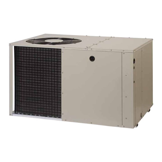
Single Package air conditioner - 3-PhaSe, r-410a
it is your responsibility to know this product better than your customer. this includes being
able to install the product according to strict safety guidelines and instructing the customer on
how to operate and maintain the equipment for the life of the product. Safety should always be
the deciding factor when installing this product and using common sense plays an important
role as well. Pay attention to all safety warnings and any other special notes highlighted in the
manual. improper installation of the furnace or failure to follow safety warnings could result in
serious injury, death, or property damage.
these instructions are primarily intended to assist qualified individuals experienced in the proper
installation of this appliance. Some local codes require licensed installation/service personnel
for this type of equipment. Please read all instructions carefully before starting the installation.
return these instructions to the customer's package for future reference.
do not deStroY. PleaSe read careFUllY & keeP in a SaFe Place For FUtUre reFerence.
iMPortant
attention inStallerS:
13 Seer
Advertisement
Table of Contents

Subscribe to Our Youtube Channel
Related Manuals for Nortek GP7RD Series


Summary of Contents for Nortek GP7RD Series
- Page 1 SerieS 13 Seer inStallation inStrUctionS Single Package air conditioner - 3-PhaSe, r-410a iMPortant attention inStallerS: it is your responsibility to know this product better than your customer. this includes being able to install the product according to strict safety guidelines and instructing the customer on how to operate and maintain the equipment for the life of the product.
-
Page 2: Table Of Contents
table oF contentS Thermostat / Low Voltage Connections ....9 iMPortant SaFetY inForMation .....3 Cooling Only Thermostat ........9 general inForMation ........4 Heat / Cool Thermostat ........9 Before You Install this Unit ........4 Reverse Rotation Verification ........9 Locating the Air Conditioner ........4 Blower Speed - ECM Motor ........9 Minimum Clearance Requirements ......4 Start UP &... -
Page 3: Important Safety Information
iMPortant SaFetY inForMation caUtion: Please read all instructions before using this equipment. Pay attention to all safety warnings and any other special this unit uses r-410a refrigerant. do not use notes highlighted in the manual. Safety markings are any other refrigerant in this unit. Use of another used frequently throughout this manual to designate a refrigerant will damage the unit. -
Page 4: General Information
general inForMation • Sufficient clearance for unobstructed airflow through the outdoor coil must be maintained in order to achieve This packaged air conditioner is designed only for outdoor rated performance. ground level installations and can be readily connected • Consideration should also be given to availability of to the high static duct system of a home. -
Page 5: Air Conditioner Installation
Single dUct aPPlication MUltiPle dUct aPPlication Figure 2. Single & Multiple duct applications • Duct work should be attached directly to the unit flanges air conditioner inStallation for horizontal applications. Unpacking the Unit • For highly resistive duct systems it may be necessary It is recommended that the unit be unpacked at the to add an additional return air duct and or supply to installation site to minimize damage due to handling. -
Page 6: Return Duct
5. Tighten first screw and rotate collar clockwise so joint the floor. However, if the floor is more than ten inches is near 3 o’clock position. deep, it will only be necessary to cut a hole for the collar on the return air box or for the insulated duct. Return Duct 3. -
Page 7: Condensate Drainage
electrical connectionS 3. Cut a 9-1/8” x 13-1/8” hole in the duct and bend over all tabs flat on the inside of the heat duct. 4. Insert the damper into the duct and bend over all tabs Warning: flat on the inside of the heat duct. 5. -
Page 8: Grounding
overcurrent Protection on the unit data label. Any other wiring methods must be acceptable to authority having jurisdiction. Generally, the best fuse or breaker for any air conditioner • The unit requires both power and control circuit electrical is the smallest size that will permit the equipment to run connections. -
Page 9: Thermostat / Low Voltage Connections
Thermostat / Low Voltage Connections Cooling Only Thermostat Connect the red & yellow wires from the unit to the r • The unit is designed to operate from a 24 VAC Class II control circuit. The control circuit wiring must comply &... -
Page 10: Start Up & Adjustments
Start UP & adJUStMentS charging the Unit in ac Mode (with Outdoor Temperatures Above 55° F) Pre-Start checklist The following check list should be observed prior to caUtion: starting the unit. √ Verify the unit is level and allows proper condensate this air conditioner contains liquid and gaseous drainage. -
Page 11: Figures & Tables
FigUreS & tableS 35” Top View 35” 49” 3” 2.48” 5.5” 9.15” 1" 3.15” 9” 17.50” 12" diameter 14" diameter Electric Heater Power Supply Supply Duct Return Duct Opening Opening Power Supply Low Voltage Supply Back (Duct) View 34.2” Control Blower Access Panel Access 17.86”... - Page 12 Figure 10. Wiring diagram for 5 ton Models...
-
Page 13: Legend
legend noteS: 1. All pressures are listed psig and all temperatures in °F Shaded boxes indicate flooded conditions. 2. Discharge temperatures greater than charted values Rated design values. The suction pressure indicate an undercharged system. will vary from design value if outdoor air flow, entering dry bulb, or entering wet bulb temperatures vary. -
Page 16: Installation / Performance Checklist
Max. deviation of voltage other reproductive harm. from avg. volts: ___________________________________ VOLTS % Volt imbalance: ________________________________ VOLTS Specifications & illustrations subject to change without notice or incurring obligations (05/15). 7097060 (neW) O’Fallon, MO, © Nortek Global HVAC LLC 2015. All Rights Reserved.
Need help?
Do you have a question about the GP7RD Series and is the answer not in the manual?
Questions and answers