Table of Contents
Advertisement
Quick Links
IR250 Infrared Receiver Specifications:
Specifications
Infrared carrier frequency: 30-60kHz
Indoor reception range:
Nominal reception angle:
Maximum wire length:
Wire requirements:
Power requirements:
Dimensions:
Requires 12VDC power supply, emitter(s) and IR54, or
IR55 connection block.
Warranty
Knoll Systems warrants its products sold in the USA and Canada by authorized
Knoll dealers to be free of defects in materials and workmanship. This warranty
extends for three full years from the date of purchase by the original consumer.
Any products returned to Knoll Systems and found to be defective by Knoll
Systems within the warranty period will be repaired or replaced at Knoll Systems
option, at no charge. Knoll Systems will not be responsible for the actual cost of
installation or removal of the product, nor for any incidental or consequential
damages. Some states do not allow the exclusion or limitation of incidental or
consequential damages, so the above limitation may not apply to you. This
warranty gives you specific legal rights. You may have additional legal rights
that vary from state-to-state.
Knoll Systems www.knollsystems.com
145 Tyee Drive Point Roberts, WA 98281
12140 Horseshoe Way, Richmond, BC V7A 4V4
Telephone: (604) 272-4555, Fax (604) 272-5595
Made in Canada
Knoll Systems All Rights Reserved
20-25 feet (6-8 meters)
50 degrees off axis
1000' (300m) or even more with
larger gauge wire
3 conductors, minimum 24-gauge
to 200'; 22-gauge up to 500';
20-gauge to 1000'
Unregulated 12VDC, 40mA
1.38" x 1.38" x 0.59"
(35mm x 35mm x 15mm)
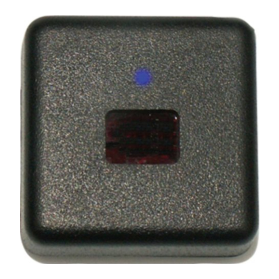
IR250
Postage Stamp Infrared Receiver
Installation Instructions v1.1
Warning: To be installed and/or used in accordance with
appropriate electrical codes and regulations.
Introduction:
Thank you for your purchase of a Knoll IR250
infrared receiver. This receiver features the ability to pick up a
remote control infrared signal and relay it on wires to another
location up to 1000' (or more).
Features:
•
Very small design available in
black and light grey colors.
•
Will relay almost all remote
control types (except some
B & O models).
•
Requires very little power. Suggest using PS1202
12 VDC 200 mA for up to 5 IR250's.
•
Up to 10 or IR10, IR21, IR22, IR230 and or IR250 can
be connected in a single system.
•
Connects with a three wire connector or RJ45 via cat 5
wire
Installation Tips
1. Follow all local electrical & building code requirements.
2. The IR250 is usually mounted to the wall using double sided
tape. For easy installation and to ensure reliability, it is
suggested that a PS1202 (200 mA) or PS1205 (500 mA) 12 VDC
unregulated power supply, IR31 (single) or IR34 (dual) emitters
and one of the following: IR54 (decora inwall style, 4 output) or
IR55 (tabletop style, 4 output) connection block, are used.
3. Wires can be solid or stranded, shielded or unshielded with a
minimum of 28-gauge for runs under 200', 22-gauge for runs
under 500' and 20-gauge for runs up to 1000'. Wires can be
Advertisement
Table of Contents

Related Manuals for Knoll IR250


Summary of Contents for Knoll IR250
-
Page 1: Installation Tips
Systems within the warranty period will be repaired or replaced at Knoll Systems option, at no charge. Knoll Systems will not be responsible for the actual cost of installation or removal of the product, nor for any incidental or consequential damages. - Page 2 5. To wire the system together, connect the IR250 12V, GND and SIG terminals to the corresponding IR54 or IR55 terminal. Prepare the wire leads to and from the IR250 by stripping about ¼” of the insulation from each of the three leads. Twist the strands tightly together so that they do not stick out of the connector and cause a short circuit.
Need help?
Do you have a question about the IR250 and is the answer not in the manual?
Questions and answers